Sony SRS-Z1000 Service Manual
Active speaker system
Hide thumbs
Also See for SRS-Z1000:
- Operating instructions (2 pages) ,
- Operating instructions manual (8 pages)

Related Manuals for Sony SRS-Z1000


Summary of Contents for Sony SRS-Z1000
- Page 1 SRS-Z1000/Z1000PC SERVICE MANUAL US Model Canadian Model Ver 1.2 1999. 05 SRS-Z1000 AEP Model With SUPPLEMENT (9-923-352-81) UK Model E Model SRS-Z1000/Z1000PC SPECIFICATIONS ACTIVE SPEAKER SYSTEM MICROFILM...
-
Page 2: Section 1 General
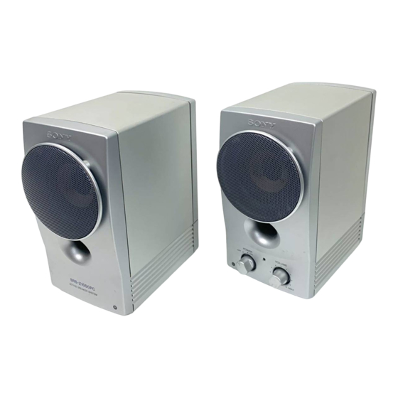
SECTION 1 This section is extracted from instruction manual. GENERAL Left speaker (Front) Power Indicator Turn the POWER switch to turn on the system. The POWER indicator lights up. Adjust the volume with the VOLUME control. — 2 —... - Page 3 SRS-Z1000/Z1000PC SECTION 2 DIAGRAMS 2-1. IC BLOCK DIAGRAM IC 1 LA4705NA — 3 — — 4 —...
-
Page 4: Amp Board
SRS-Z1000/Z1000PC 2-2. PRINTED WIRING BOARD AMP BOARD POWER DC IN 15V 1A ON/OFF LED BOARD INPUT D101 PLUG R OUT SP RELAY BOARD R-CH L-CH 8Ω 8Ω • Semiconductor Location Ref. No. Location D101 Note on Printed Wiring Board: • X : parts extracted from the component side. -
Page 5: Schematic Diagram
SRS-Z1000/Z1000PC 2-3. SCHEMATIC DIAGRAM MAIN BOARD LA4705NA POWER AMP 0.0022 NJM2114D 1u 50V 1u 50V 1u 50V – – 3.3k 3.3k 3.3k 13 14 17 18 2SC2458LGR 1000P RV1(1/2) (1/2) 0.15 1000P 1000P 1.5k 1000P L-CH 8Ω VOLUME 10u 50V... -
Page 6: Section 3 Exploded Views
SRS-Z1000/Z1000PC SECTION 3 EXPLODED VIEWS 3-1. CABINET (R) SECTION NOTE: • -XX, -X mean standardized parts, so they may • The mechanical parts with no reference number have some differences from the original one. in the exploded views are not supplied. -
Page 7: Section 4 Electrical Parts List
SECTION 4 AMPLIFIER ELECTRICAL PARTS LIST NOTE: • Due to standardization, replacements in the • RESISTORS When indicating parts by reference number, parts list may be different from the parts All resistors are in ohms. please include the board name. specified in the diagrams or the components METAL: metal-film resistor The components identified by mark ! or... - Page 8 SRS-Z1000/Z1000PC Ver 1.1 1999. 05 AMPLIFIER Ref. No. Part No. Description Remarks Ref. No. Part No. Description Remarks 1-249-407-11 CARBON 1/4W F 1-668-102-11 LED BOARD 1-249-429-11 CARBON 1/4W ********* 1-247-843-11 CARBON 3.3K 1/4W 1-247-843-11 CARBON 3.3K 1/4W < DIODE >...
- Page 9 File this supplement with the Service Manual. Subject : SRS-Z1000PC: Australian model is added. • SRS-Z1000PC: Difference of the Australian model from other models is AC adaptor only. Please refer to SRS-Z1000/Z1000PC service manual (9-923-352-11) preriously issued for other information. • PART LIST Ref. No.