Bosch rexroth IndraControl XFE 01.1 Operating Manual
Extension modules profibus, rt-ethernet, sercos, can
Hide thumbs
Also See for rexroth IndraControl XFE 01.1:
- Operating instructions manual (44 pages) ,
- Operating instructions manual (36 pages)

Related Manuals for Bosch rexroth IndraControl XFE 01.1


Summary of Contents for Bosch rexroth IndraControl XFE 01.1
- Page 1 Operating Manual IndraControl XFE 01.1 Extension Modules Profibus, RT-Ethernet, Sercos, CAN R911345570, Edition 06...
- Page 2 Copyright © Bosch Rexroth AG 2021 All rights reserved, also regarding any disposal, exploitation, reproduction, editing, distribution, as well as in the event of applications for industrial property rights. Liability The specified data is intended for product description purposes only and shall not be deemed to be a guaranteed characteristic unless expressly stipulated in the contract.
-
Page 3: Table Of Contents
UL/CSA certified ..........13 Marine and offshore certification (XFE01.1-FB-03, XFE01.1-FB-20)..Interfaces of the XFE modules R911345570, Edition 06 Bosch Rexroth AG... - Page 4 16.2 Packaging............31 17 Service and support Index Bosch Rexroth AG R911345570, Edition 06...
-
Page 5: About This Documentation
Program Test Maintain Dispose Activities Design Install Configure Remove faults Construct Simulate Create the NC program Fig. 1: Assigning the present documentation to the target groups, product phases and activities of the target group R911345570, Edition 06 Bosch Rexroth AG... -
Page 6: Scope
Customer requests, comments or suggestions for improvement are of great importance. Please email your feedback on the documentations to Feedback.Documentation@boschrexroth.de. Directly insert ⮫ comments into the electronic PDF document and send the PDF file to Bosch Rexroth. Bosch Rexroth AG R911345570, Edition 06... -
Page 7: Product Identification And Scope Of Delivery
Product identification and type plate Rexroth IndraControl XFE MNR: R911172531 -AA0 7260 S N : 7260007123456B C FD: 12W16 FW: 101 FI: 001 Bosch Rexroth AG, Bgm.-Dr.-Nebel-Str. 2 Functional Safety DE-97816 Lohr Hotline: +49 9352 405060 Type Approved www.tuv.com Made in Germany CERTIFIED... -
Page 8: Scope Of Delivery
In case of non-compliance with this safety instruction, death or serious injury WARNING can occur. In case of non-compliance with this safety instruction, minor or moderate CAUTION injury can occur. In case of non-compliance with this safety instruction, material damage can NOTICE occur. Bosch Rexroth AG R911345570, Edition 06... -
Page 9: Symbols Used
Ordering code Part number Description S20-CNS 2S-O/D/UI/E1/E2 R911173804 Connector set for the 24 V module and the CAN module Bus base module Ordering code Part number Description XA-BS11 R911173772 Bus base module for extension modules R911345570, Edition 06 Bosch Rexroth AG... -
Page 10: End Clamp
The vibration stress specifications assume the use of industrial-suited RJ45 plug connec- ① tions. The “Industrial RJ45 plug” of the company Yamaichi is recommended (Y-ConPlug-41). The cables are available as accessories (RKB0020). To avoid vibration, secure the cables at a short distance (< 20 cm). Bosch Rexroth AG R911345570, Edition 06... -
Page 11: Technical Data
4.8 W max. Reverse voltage protection of the supply voltage Diode Fuse protection Internal protective fuse, 4 A Transient protection Present, suppressor diodes Voltage dips at current supply interfaces Up to 10 ms without impairment R911345570, Edition 06 Bosch Rexroth AG... -
Page 12: Electrical Isolation And Isolation Of The Voltage Ranges
The products have been developed according to the German editions of the standards published at the time of product engineering. Standards used Table 6: Standards used Standard Meaning Edition IEC 60204-1 Electrical equipment of machines 2007 IEC 61131-2 Programmable logic controllers 2008 Bosch Rexroth AG R911345570, Edition 06... -
Page 13: Ce Marking
UL marking on the device. Loss of UL/CSA conformity due to modifications at the device. UL and CSA marking applies only to the device upon delivery. After modifying the device, verify the UL and the CSA conformity. R911345570, Edition 06 Bosch Rexroth AG... -
Page 14: Marine And Offshore Certification (Xfe01.1-Fb-03, Xfe01.1-Fb-20)
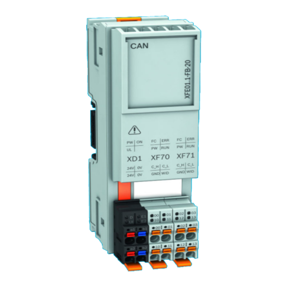
To search for certificates, enter one of the above mentioned certificate numbers (DCTC_xxxxx_xxx) into the search field in the upper right. Interfaces of the XFE modules Fig. 4: Interfaces of the extension modules Bosch Rexroth AG R911345570, Edition 06... - Page 15 CAN ground 11 or 13 Adding the termination resistor to the CAN network The resistor is enabled by connecting the plug contacts 10 (CAN GND) and 11 (WID) or 12 (CAN GND) and 13 (WID). R911345570, Edition 06 Bosch Rexroth AG...
-
Page 16: Mounting, Dismounting And Electric Installation
Housing dimensions of the XFE module 54.8 * 41.6 50.8 52.4 Fig. 5: Housing dimensions The dimensions depend on the respective extension module ① Mounting rail TH 35 – 7.5 acc. to DIN EN 60715 ② Mounting rail center Bosch Rexroth AG R911345570, Edition 06... -
Page 17: Installation Notes
● It impedes the shifting of the control. ● The installation place for the end clamps is secured. ● If the control has to be replaced, there is sufficient space to separate the control from the bus base modules. R911345570, Edition 06 Bosch Rexroth AG... -
Page 18: Mounting
+55 C, use cables approved for temperatures of at least +75°C. 10.3 Mounting Damages at the contacts by tilting the modules NOTICE Attach the modules vertically on the mounting rail and remove the modules vertically from the mounting rail. Bosch Rexroth AG R911345570, Edition 06... -
Page 19: 10.3.1 Mounting Extension Bus Base Modules
Move the other extension bus base modules to the right until all bus base modules are connected to each other (see (C) in the following figure). Fit the extension modules and the XMx control on the bus bases. R911345570, Edition 06 Bosch Rexroth AG... -
Page 20: Dismounting
The base latches are locked in the open position. Remove the extension module vertically to the mounting rail (see (B) in the following figure). The base latches engage again in idle position. Bosch Rexroth AG R911345570, Edition 06... -
Page 21: Electric Installation
10.5.2 External power supply unit All control components are supplied from 24 V voltage supplies. Use the Bosch Rexroth power supply unit VAP01.1H-W23-024-010-NN, part number R911171065, for the logic supply. For further information on the external power supply unit and on the creation of overvoltage categories, refer to the documentation of the power supply unit. - Page 22 22. Other connection variants are not permitted. 54.8 * 41.6 50.8 52.4 Fig. 11: Mandatory voltage supply ① 24 V voltage supply ② Top-hat rail ③ Extension module ④ XM2x control ⑤ S20 Module Bosch Rexroth AG R911345570, Edition 06...
-
Page 23: 10.5.3 Voltage Supply For The Control And For The Extension Modules
Connect the power connector with cables with a conductor cross-section of AWG 16 (1.5 mm Observe the color-coding of the plugs. Only the “XA-CN01” power connector is permitted to connect the 24 V supply voltage (see ⮫ Chapter 5.1 “Power connectors, 24 V” on page R911345570, Edition 06 Bosch Rexroth AG... -
Page 24: Voltage Supply
Operating systems and machines requires the implementation of a comprehensive concept for state-of- the-art IT security. Bosch Rexroth products are part of this comprehensive concept. The properties of the Bosch Rexroth products have to be considered for a comprehensive IT Security concept. For the required properties, refer to the IT Security Guideline (⮫... -
Page 25: Device Description
LED off: No error LED off: No error Table 13: Profibus extension module Color Function Stat Green LED is permanently on: Communication present LED is acyclically on: Module not configured LED is cyclically on: Module configured R911345570, Edition 06 Bosch Rexroth AG... -
Page 26: Leds On The Xd1 Plug
The following function is assigned to the LED on the XD1 plug: Table 16: LED function on the XD1 plug Color Function Green Internal voltages are present Green Internally programmed function blocks are loaded Green 24 V supply voltage connected and within the permitted range Bosch Rexroth AG R911345570, Edition 06... -
Page 27: Error Causes And Troubleshooting
LED flashes (2 Hz): System error: invalid configuration, moni- toring error or internal error LED on (together with BF “red on"): Invalid master license • Slave: LED on: Watchdog timeout; channel, generic or extended diag- nostics present; system error R911345570, Edition 06 Bosch Rexroth AG... -
Page 28: 13.1.1 Error Cases After Commissioning The Can Module
Communication error, refer to the CANopen standard “CIA 303 Part 3: Indicator Specification” 13.1.1 Error cases after commissioning the CAN module The following errors can be displayed when commissioning the CAN module, also refer to ⮫ Chapter 11.1 “Commissioning notes ” on page Bosch Rexroth AG R911345570, Edition 06... -
Page 29: Maintenance
Maintenance work in the device is only permitted by trained staff! NOTICE If hardware or software components have to be exchanged, please contact the Bosch Rexroth Service or ensure that only skilled staff changes the respective components. 14.2 Scheduled maintenance tasks Include the following tasks into the maintenance schedule: •... -
Page 30: Ordering Information
30 / 36 IndraControl XFE 01.1 Type code Ordering information 15.1 Type code Fig. 16: Type code Bosch Rexroth AG R911345570, Edition 06... -
Page 31: Accessories And Spare Parts
Furthermore, the products returned for disposal must not contain any undue foreign substances or external components. Send the products free of charge to the following address: Bosch Rexroth AG Electric Drives and Controls Bürgermeister-Dr.-Nebel-Straße 2 97816 Lohr am Main, Germany 16.2... -
Page 32: Service And Support
Detailed description of malfunction and circumstances • Type plate specifications of the affected products, in particular type codes and serial numbers • Your contact data (phone and fax number as well as your e-mail address) Bosch Rexroth AG R911345570, Edition 06... -
Page 33: Index
Housing dimensions..... . 16 Symbols....... . 9 R911345570, Edition 06 Bosch Rexroth AG... - Page 34 Warnings....... . 8 Wear parts......9, 10 Bosch Rexroth AG R911345570, Edition 06...
- Page 35 IndraControl XFE 01.1 35 / 36 R911345570, Edition 06 Bosch Rexroth AG...
- Page 36 Bosch Rexroth AG P.O. Box 13 57 97803 Lohr a.Main, Germany Bgm.-Dr.-Nebel-Str. 2 97816 Lohr a.Main, Germany Tel. +49 9352 18 0 Fax +49 9352 18 8400 www.boschrexroth.com/electrics R911345570 R911345570...