Philips PET724 Service Manual
Hide thumbs
Also See for PET724:
- Service manual (28 pages) ,
- User manual (5 pages) ,
- Specifications (2 pages)
Advertisement
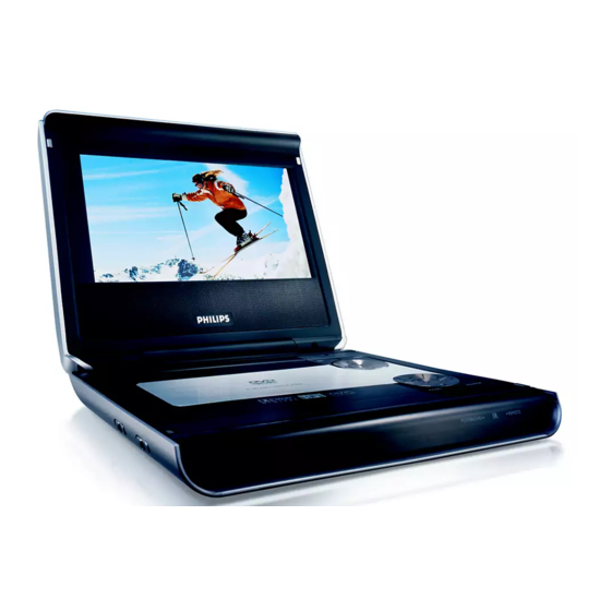
DVD Portable Player
Service Manual
TABLE OF CONTENTS
Technical Specification............................................. 1
Safety Instructions................................................... 2
Instruction for Use......................................................3
Mechanical Instructions............................................. 4
Troubleshooting & Service Tips................................. 5
Overall Block Diagram................................................ 6
Overall Wiring Diagram............................................. 7
Electrical Diagram...................................................... 8
Component Layout..................................................... 9
Exploded View Diagram & Service Part List...................10
IRIS Code..................................................................11
Revision List............................................................. 12
©Copyright 2005 Philips Consumer Electronics B.V. Eindhoven, The Netherlands
OSD TEST
All rights reserved. No part of this publication may by reproduced, stored in a
CONFIGURATION SETUP
retrieval system or transmitted, in any form or by any means, electronics,
mechanical, photocopying, or otherwise without the prior permission of Philips
Version 1.6
PET724/PET725/PET728
Chapter
All version
3141 785 30836
Advertisement

Related Manuals for Philips PET724


Summary of Contents for Philips PET724
-
Page 1: Table Of Contents
All rights reserved. No part of this publication may by reproduced, stored in a CONFIGURATION SETUP retrieval system or transmitted, in any form or by any means, electronics, mechanical, photocopying, or otherwise without the prior permission of Philips 3141 785 30836 Version 1.6... -
Page 2: Technical Specification
E.g. 050303 Procedure on how to upgrade the software of the DVD Current consumption Portable Download the latest software from the Philips support site. DC-IN SUPPLY (9.0V) Unzipped the files and then burn it onto a CD ROM Battery Charging Current 1.2A typ. - Page 3 2.0 SAFTETY INSTRUCTIONS WAARSCHUWING WARNING Alle IC’s en vele andere halfgeleiders zijn All ICs and many other semi-conductors are gevoelig voor electrostatische ontladingen susceptible to electrostatic discharges (ESD). (ESD). Careless handling during repair can reduce life Onzorgvuldig behandelen tijdens reparatie kan drastically.
- Page 4 2.1 ESD PROTECTION When the power supply is being turned on, you may not remove this laser cautions label. If it removes, radiation of laser may be received. PREPARATION OF SERVICING Pickup Head consists of a laser diode that is very susceptible to external static electrocity. Although it operates properly after replacement, if it was subject to electrostatic discharge during replacement, its life might be shortened.
- Page 5 SAFTY NOTICE SAFTY PRECAUTIONS LEAKAGE CURRENT CHECK Plug the AC line cord directly into a 120V AC outlet (do Measure the AC voltage across the 1500 resistor. not use an isolation transformer for this check). Use an The test must be conducted with the AC switch on and AC voltmeter, having 5000 per volt or more sensitivity.
-
Page 6: Instruction For Use
3.0 INSTRUCTIONS FOR USE MENU DVD PLAYER LAYOUT POWER/CHG Displays MENU page Power and charging indicator Remote sensor On Screen Display on / off OPEN , , , Opens disc door to insert or Up / down / left / right cursor remove disc ON . - Page 7 Remote Control , , , 7 0 - 9 Up / down / left / right cursor Numeric keypad Confirms selection 8 MUTE Muting play volume VOLUME REPEAT Volume control Repeats chapter / title / disc 9 RETURN For previous ( ) or next ( ) For VCD menu page chapters, tracks or titles ANGLE...
- Page 8 4.0 MECHNICAL INSTRUCTIONS 1. Back View as Fig.1 4. Remove key board and other parts as Fig.5 Remove screws to remove base Fig.5 Fig.1 5. Remove top cover as Fig.6 2. Disconnect key control wire and 20 pins harness, Remove screws to dismentle the plate, Soldered short pattern for laser diode as Fig.2 20 pins harness key control wire...
-
Page 9: Troubleshooting & Service Tips
5.0 TROUBLESHOOTING & SERVICE TIPS Procedure to change regioncode 1. Power on player and open DVD Door. 2. Press <Set Up> at Remote Control. In <Set Up Menu> select <Preferences> then press <OK>. 3. For PET72x - Press successively 2 1 2 2 2 5. . . 4. - Page 10 5.0 TROUBLESHOOTING & SERVICE TIPS SYMPTOM: NO POWER, NO GREEN LED start Check if the power cable replace cable/ No defect, return set OK? adapter set to customer AC adapter Check if the replace connector power and play and switch unit button OK? replace MAIN go to other...
- Page 11 5.0 TROUBLESHOOTING & SERVICE TIPS SYMPTOM: THE INITIAL SCREEN IS NOT DISPLAYED ON THE LCD Refer to the symptom NO start POWER, NO GREEN LED Replace broken Check if the Repair connector harness LED on the front lights up? Remove the LCD Open the top and Is the cover and plate of...
- Page 12 5.0 TROUBLESHOOTING & SERVICE TIPS SYMPTOM: THE DVD DRIVE DOES NOT WORK Press the DISC cover switch at the center of the DVD player and turn on the power. Then check whether or not the optical pick- up lens of the DVD drive lights. CAUTION: start Visible laser radiation when open and interlock defeated.
- Page 13 5.0 TROUBLESHOOTING & SERVICE TIPS SYMPTOM: THE DVD DRIVE DOES NOT OPERATE WITH BATTERY start Install a good battery does the LED lights up orange while the AC adapter is connected and does the DVD drive operate OK? NOTE: - For this check, use a battery which is not fully Replace battery charged (because the LED does not light when the battery is fully charged.)
-
Page 14: Overall Block Diagram
6.0 OVERALL BLOCK DIAGRAM OSCILLATOR DC 9V 16M FlashROM 64M SDRAM OZ9RR 27MHz TC4W53 74HCU04 MX29LV160ABTC-70 HY57V641620ETP-H 27MHz HIGH VOLTAGE ASS'Y MX88V462UCG TFT MONITOR RF AMP & SERVO & DVD PROCESSOR DV23(HD80) MPEG-2 DECODER & VIDEO ENCODER PU mechanism MT1389DE VIDEO IN +3.3V +1.8V... -
Page 15: Overall Wiring Diagram
7.0 OVERALL WIRING DIAGRAM SWITCH PCB HV POWER PCB HV GND BRIGHT TFT ON/OFF BATT+ LD/VCC XS001 CD/DVD SW BATTERY VCOMS 3.3V VRCD VRDVD VCOMS LD/CD TFT-16V LD/DVD SPIO MODE2 MODE1 SPOI FCS- SPIO TRK+ MODE1 TRK- FCS+ VDD1 SPOI LIMIT LCD R TFT +5V... -
Page 16: Electrical Diagram
8.0 ELECTRICAL DIAGRAM MAIN BOARD CIRCUIT DIAGRAM (MPEG) JITFO 390pF JITFN DV33 RFV33 RFV33 RFVDD3 ADACVDD Crystal 750k 10uH APLLVDD3 2200pF 0.1uF/NC DACVDD3 680k ADIN 0.1uF 0.01uF 2200pF CE14 10uF/10v 10uF/6.3v 100k 0.1uF C10UF6.3V/D4H5 10uF/6.3v 10uF/10v CE31 CB48 1000uF/10v 0.1uF 150k 150k R130... - Page 17 8.0 ELECTRICAL DIAGRAM MAIN BOARD CIRCUIT DIAGRAM (FLASH & SDRAM) D004 $$$148 $$$150 $$$151 $$$152 $$$153 $$$155 $$$156 $$$190 $$$157 $$$189 $$$191 $$$158 $$$188 $$$192 $$$159 DV33 $$$187 $$$193 MA10 $$$160 $$$186 A10/AP DQ10 $$$194 MA11 $$$161 $$$185 DQ11 $$$195 $$$165 $$$184 BA0/A13...
- Page 18 Crystal 8.0 ELECTRICAL DIAGRAM MAIN BOARD CIRCUIT DIAGRAM (TFT) CLK_IN CLK_OUT R257 R256 C131 27MHz C128 +P5V 20pF 20pF 100UH C228 1N C225 C221 C2220 C227 470P 10UF 10UF 100N C226 D2V5 R255 470N AAT1109 VD37 R280 TFT-13V AO3402 100UH C285 10UF VD38...
- Page 19 8.0 ELECTRICAL DIAGRAM MAIN BOARD CIRCUIT DIAGRAM (DC POWER) #HV9V L005 C091 C024 C167 C077 C088 CDRH6D38-330MC 10U/10V 100N 100U/10V 16v/100u 100N 100N DRVCC 5V5 CATION:REPLACE PUSE WITH SAME 5.5V OUT TYPE AND RATING VD101 BA05 Littelfuse C010 C129 C128 C138 C021 T3A/125V...
- Page 20 8.0 ELECTRICAL DIAGRAM MAIN BOARD CIRCUIT DIAGRAM (AUDIO) PCM1753 ACLK ABCK DV33 ASDATA0 DATA ALRCK R558 R158 +P5V LRCK R559 VD524 DV33 DGND KTA1298 +P5V +3.3V ZERONA MUTE VD522 1SS355 R567 R556 VD525 1SS355 R557 VD520 100k ZERO OA CB128 CB129 LOUT C554 47U/4V...
- Page 21 8.0 ELECTICAL DIAGRAM - HIGH VOLTAGE BOARD CIRCUIT DIAGRAM 1210 UI8.5 SOT-23 SOT-23...
-
Page 22: Component Layout
9.0 COMPONENT LAYOUT IF BOARD DIAGRAM HV BOARD DIAGRAM... - Page 23 9.0 COMPONENT LAYOUT MAIN BOARD DIAGRAM...
- Page 24 10.0 SERVICE PARTS LIST The following service BOMs are applied for all version unless specified. Model# Service 12NC Description Photos Location Code PET724 PET725 994000004182 LITHIUM BATTERY BATTERY PET728 PET724 PET725 994000001912 PET725 AV CABLE AVCABLE PET728 PET725 994000004528 TRAVEL BAG...
- Page 25 10.0 SERVICE PARTS LIST The following service BOMs are applied for all version unless specified. Location Model# Service 12NC Description Photos Code PET724 994000004191 PET724 MAIN PCBA PET725 PET728 PET725/58 MAIN PCBA 996500038604 (for S/N: LL01xxxxxxxx) PET725/58 PET725/58 LED MAIN 996510002003 PCBA...
- Page 26 (for S/N: LL2Bxxxxxxxx) PET724 PET725 994000002228 DV23 LOADING ASS’Y PET728 PET724 PET725 994000002157 SPEAKER PET728 PET724 PET725 994000004196 PET724 SPEAKER GRILL PET728 PET724 994000004187 PET724 TOP COVER PET725 994000004526 PET725 TOP COVER PET728 PET724 PET725 994000004188 PET724 DISPLAY FRAME PET728...
- Page 27 10.0 SERVICE PARTS LIST The following service BOMs are applied for all version unless specified. Location Model# Service 12NC Description Photos Code 994000004186 PET724 BASE COVER PET724/37 PET725/00 994000004525 PET725 BASE COVER PET725/05 PET728/00 PET725/44 BOTTOM 994000005199 PET725/44 COVER 994000005793...
- Page 28 The following service BOMs are applied for all version unless specified. Location Model# Service 12NC Description Photos Code PET725 996500040950 DOOR HOOK PET728 PET724 PET725 994000004189 PET724 DOOR SPRING PET728 PET724 PET725 994000002469 TOP COVER SPRING PET728 314017910141 DTM150 TECHNICAL SET PET728/00 ADAPTOR AC TO DC 9V PET728/00 314107941051 ACADAPTOR 1.11A...
-
Page 29: Revision List
11.0 REVISION LIST Version 1.0 (3141 785 30830) • Initial release PET724 & PET725 Version 1.1 (3141 785 30831) • Updated service parts to include PET725/44 Version 1.2 (3141 785 30832) • Updated service parts to include PET725/75 and PET725/58 Version 1.3 (3141 785 30833)