Table of Contents
Advertisement
Preface
The purpose of this publication is to provide the service
technician with information for troubleshooting, testing
and repair of major systems and components on the
Greens Aerator.
REFER TO THE OPERATOR'S MANUALS FOR OP-
ERATING,
MAINTENANCE
INSTRUCTIONS. Space is provided in Chapter 2 of this
book to insert the Operator's Manuals and Parts Cata-
logs for your machine. Replacement Operator's Manu-
als are available on the internet at www.toro.com or by
sending complete Model and Serial Number to:
The Toro Company
Attn. Technical Publications
8111 Lyndale Avenue South
Minneapolis, MN 55420
The Toro Company reserves the right to change product
specifications or this publication without notice.
AND
ADJUSTMENT
E The Toro Company – 2004
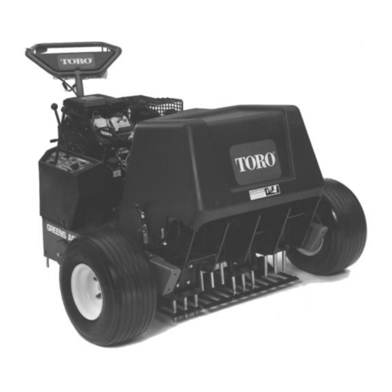
Service Manual
Greens Aerator
This safety symbol means DANGER, WARNING,
or CAUTION, PERSONAL SAFETY INSTRUC-
TION. When you see this symbol, carefully read
the instructions that follow. Failure to obey the
instructions may result in personal injury.
NOTE: A NOTE will give general information about the
correct operation, maintenance, service, testing or re-
pair of the machine.
IMPORTANT: The IMPORTANT notice will give im -
portant instructions which must be followed to pre-
vent damage to systems or components on the
machine.
Part No. 04133SL
Advertisement
Chapters
Table of Contents
Troubleshooting

Related Manuals for Toro Greens Aerator


Summary of Contents for Toro Greens Aerator
- Page 1 Operator’s Manuals and Parts Cata- logs for your machine. Replacement Operator’s Manu- als are available on the internet at www.toro.com or by sending complete Model and Serial Number to: NOTE: A NOTE will give general information about the...
- Page 2 This page is intentionally blank. Greens Aerator...
- Page 3 Testing ........4 – 11 Service and Repairs ..... . . 4 – 14 Greens Aerator...
- Page 4 This page is intentionally blank. Greens Aerator...
-
Page 5: Table Of Contents
JACKING INSTRUCTIONS ..... 4 SAFETY AND INSTRUCTION DECALS ..5 Greens Aerator Safety... -
Page 6: Safety Instructions
Safety Instructions The Greens Aerator is designed and tested to offer safe service when operated and maintained properly. Al- WARNING though hazard control and accident prevention partially are dependent upon the design and configuration of the To reduce the potential for injury or death, machine, these factors are also dependent upon the comply with the following safety instructions. -
Page 7: Maintenance And Service
To assure optimum sired, contact an Authorized Toro Distributor. performance and continued safety certification of the machine, use genuine Toro replacement parts and ac- 8. Use care when checking or servicing the coring cessories. Replacement parts and accessories made head: wear gloves and use caution. -
Page 8: Jacking Instructions
(Fig. 3). 4. Jack rear of machine off the ground. Figure 3 1. Rear wheel 2. Frame jacking point 5. Position jack stands or hardwood blocks under the frame to support the machine. Safety Greens Aerator Page 1 – 4... -
Page 9: Safety And Instruction Decals
Safety and Instruction Decals Numerous safety and instruction decals are affixed to the Greens Aerator. If any decal becomes illegible or damaged, install a new decal. Part numbers for replace- ment decals are listed in your Parts Catalog. Order re- placement decals from your Authorized Toro Distributor. - Page 10 This page is intentionally blank. Safety Greens Aerator Page 1 – 6...
- Page 11 Maintenance Maintenance procedures and recommended service in - tervals for the Greens Aerator are covered in the Opera- tor’s Manual. Refer to that publication when performing regular equipment maintenance. Refer to the Engine Operator’s Manual for additional engine specific main-...
- Page 12 Equivalents and Conversions Product Records and Maintenance Greens Aerator Page 2 – 2...
- Page 13 For critical applications, as determined reduced by 25% for lubricated fasteners to achieve by Toro, either the recommended torque or a torque that the similar stress as a dry fastener. Torque values may is unique to the application is clearly identified and spe - also have to be reduced when the fastener is threaded cified in this Service Manual.
- Page 14 The specific torque value should be determined based on the fastener size, the aluminum or base material strength, length of thread engagement, etc. Product Records and Maintenance Greens Aerator Page 2 – 4...
- Page 15 The specific torque value should be determined based on the fastener size, the aluminum or base material strength, length of thread engagement, etc. Greens Aerator Product Records and Maintenance Page 2 – 5...
- Page 16 All torque values are based on non–lubricated fasteners. Conversion Factors in–lb X 11.2985 = N–cm N–cm X 0.08851 = in–lb ft–lb X 1.3558 = N–m N–m X 0.7376 = ft–lb Product Records and Maintenance Greens Aerator Page 2 – 6...
- Page 17 Service and repair parts for the engine used in the General engine maintenance procedures are described Greens Aerator are supplied through your local engine in your Operator’s Manual. Information on engine trou- dealer or distributor (Briggs & Stratton or Kohler).
-
Page 18: Specifications
NOTE: High Idle when shift lever is in reverse position 1400 to 1800 RPM Engine Oil See Operator’s Manual Oil Pump Gear Driven Geroter Type Crankcase Oil Capacity 1.75 Quarts (1.66 Liters) with New Filter Starter 12 VDC Engine Greens Aerator Page 3 – 2... -
Page 19: Model 09100 And 09110
1.5 U.S. Gallons (5.7 Liters) Governor Mechanical Idle Speed (no load) 1300 RPM High Idle (no load) 3600 RPM Engine Oil See Operator’s Manual Crankcase Oil Capacity 5.25 Pints (2.5 Liters) Starter 12 VDC Greens Aerator Page 3 – 3 Engine... - Page 20 This page is intentionally blank. Engine Greens Aerator Page 3 – 4...
-
Page 21: Service And Repairs
5. Make sure rotating screen and blower housing are reinstalled to the engine if removed. NOTE: For additional information regarding the engine cooling system, refer to the engine service manual at the end of this chapter. Greens Aerator Page 3 – 5 Engine... -
Page 22: Fuel System
5. Flat washer (3 used) 12. Socket head screw 19. Fuel stand pipe 6. Cap screw (3 used) 13. Lock washer 20. Fuel cap 7. Rear bracket 14. Flat washer 21. Front bracket Engine Greens Aerator Page 3 – 6... - Page 23 Make sure tank is free of hose with hose clamp. contaminates and debris. 3. Fill fuel tank (see Operator’s Manual). 4. Return coring head lock–up brackets to stored posi- tion. Greens Aerator Page 3 – 7 Engine...
-
Page 24: Exhaust System
6. Flat washer (2 used) 12. Self tapping screw (4 used) 18. Muffler mount NOTE: On Models 09100 and 09110 equipped with a Kohler M16 engine, exhaust system service is similar to the following procedure. Engine Greens Aerator Page 3 – 8... - Page 25 (4) cap screws (item 17) and lock washers fasteners removed during disassembly. (item 16) from the engine. Separate the exhaust tubes 6. Return coring head lock–up brackets to stored posi- from the engine. tion. 7. Remove exhaust gaskets (not shown). Greens Aerator Page 3 – 9 Engine...
-
Page 26: Engine
50. Set screw (2 used) 17. Throttle control rod 34. Flat washer 51. Key NOTE: On Models 09100 and 09110 equipped with a Kohler M16 engine, engine removal and installation is similar to the following procedure. Engine Greens Aerator Page 3 – 10... - Page 27 Repairs section of Chapter 4 – Hydraulic System). 10.Disconnect spring (item 18) from clevis pin in shift plate (Fig. 8). Figure 7 1. Engine flywheel pulley 3. Set screw (2 used) 2. Hydraulic pump drive belt Greens Aerator Page 3 – 11 Engine...
- Page 28 C. Secure engine mount plate to the frame with four gine uses two (2) lock washers (item 45). (4) cap screws (item 42) and lock washers. Engine Greens Aerator Page 3 – 12...
- Page 29 19.Return coring head lock–up brackets to stored posi- tor’s Manual). tion. 10.Install coring head drive belt to the engine PTO pulley (see Coring Head Drive Belt in the Service and Repairs section of Chapter 8 – Coring Head). Greens Aerator Page 3 – 13 Engine...
- Page 30 This page is intentionally blank. Engine Greens Aerator Page 3 – 14...
- Page 31 TESTING ........11 TEST NO. 1: System Relief Pressure ..12 Greens Aerator Page 4 – 1...
-
Page 32: Specifications
Specifications Item Description Hydraulic Pump Vane Pump, Belt Driven System Relief Pressure 1300 PSI (89.6 Bar) Hydraulic Oil 10W30 Engine Oil Hydraulic Reservoir Capacity 2.7 Pints (1.3 Liters) Hydraulic System Page 4 – 2 Greens Aerator... -
Page 33: General Information
General Information Hydraulic System Fluid The Greens Aerator hydraulic system is designed to op- erate on SAE 10W–30 engine oil or, as a substitute, SAE 10W–40 engine oil. Check level of hydraulic fluid dai - See Operator’s Manual for fluid level checking proce- dure. -
Page 34: Hydraulic Hoses
6 (3/8 in.) 0.75 + 0.25 8 (1/2 in.) 0.75 + 0.25 10 (5/8 in.) 1.00 + 0.25 Figure 4 12 (3/4 in.) 0.75 + 0.25 16 (1 in.) 0.75 + 0.25 Hydraulic System Page 4 – 4 Greens Aerator... - Page 35 6 (3/8 in.) 1.50 + 0.25 8 (1/2 in.) 1.50 + 0.25 10 (5/8 in.) 1.50 + 0.25 12 (3/4 in.) 1.50 + 0.25 Figure 8 16 (1 in.) 1.50 + 0.25 Greens Aerator Page 4 – 5 Hydraulic System...
-
Page 36: Hydraulic Schematic
Hydraulic Schematic LIFT CYLINDER LIFT CONTROL VALVE HYDRAULIC PUMP INTERNAL 1300 PSI RELIEF VALVE PUMP RESERVOIR Greens Aerator Hydraulic Schematic Hydraulic System Page 4 – 6 Greens Aerator... -
Page 37: Hydraulic System Operation
Lift cylinder movement is stopped. The cylinder position is locked in place since there is no complete circuit of flow to and from the lift cylinder. Greens Aerator Page 4 – 7 Hydraulic System... -
Page 38: Special Tools
Special Tools Order these special tools from the TORO SPECIAL TOOLS AND APPLICATIONS GUIDE (COMMERCIAL PROD- UCTS). Hydraulic Pressure Test Kit Part Number: TOR47009 Use to take various pressure readings for diagnostic tests. Quick disconnect fittings provided attach directly to mating fittings on machine test ports without tools. A high pressure hose is provided for remote readings. -
Page 39: Troubleshooting
Á Á Á Á Á Á Á Á Á Á Á Á Á Á Á Á Á Á Á Á Á Á Á Á Á Á Á Á Á Á Á Á Á Á Á Greens Aerator Page 4 – 9... - Page 40 This page is intentionally blank. Hydraulic System Page 4 – 10 Greens Aerator...
-
Page 41: Testing
If fluid is injected into the skin, it must be surgically removed within a few hours by a doctor familiar with this type of injury. Gangrene may result from such an injury. Greens Aerator Page 4 – 11 Hydraulic System... -
Page 42: Test No. 1: System Relief Pressure
TEST NO. 1: System Relief Pressure (Using Pressure Gauge) LIFT CYLINDER PRESSURE GAUGE LIFT CONTROL VALVE HYDRAULIC PUMP INTERNAL 1300 PSI RELIEF VALVE Working Pressure Return or Suction Flow Direction PUMP RESERVOIR Figure 11 Hydraulic System Page 4 – 12 Greens Aerator... - Page 43 (89.6 Bar). 12.If specification is not met, inspect pressure control valve located in hydraulic pump. 13.Disconnect pressure gauge and T–fitting from hy- draulic hose and lift cylinder. Connect hydraulic hose to lift cylinder. Greens Aerator Page 4 – 13 Hydraulic System...
-
Page 44: Service And Repairs
If fluid is in- jected into the skin, it must be surgically re- moved within a few hours by a doctor familiar with this type of injury. Gangrene may result from such an injury. Hydraulic System Page 4 – 14 Greens Aerator... -
Page 45: Hydraulic System Start-Up
3. Make sure all hydraulic connections and lines are se - leaks and tighten any loose connections. cured tightly. 4. Disconnect and ground both spark plug wires to pre- vent engine from starting. Greens Aerator Page 4 – 15 Hydraulic System... -
Page 46: Hydraulic Pump Drive Belt
4. Engine pulley 10. Hydraulic pump 16. Self tapping screw (2 used) 5. Shield 11. Pump drive belt 17. Jam nut 6. Hex nut 12. Hydraulic pump pulley 18. Square head screw Hydraulic System Page 4 – 16 Greens Aerator... - Page 47 Drive Belt Installation (Fig. 13) 1. Install pump drive belt to hydraulic pump and engine pulleys. 2. Adjust pump drive belt tension (see Operator’s Manual). 3. Install control cover to machine (Fig. 14). Greens Aerator Page 4 – 17 Hydraulic System...
-
Page 48: Hydraulic Pump
Loosen jam nut draulic oil. (item 21) and then loosen square head screw (item 22) to relax pump drive belt. Remove drive belt from the hy- draulic pump pulley. Hydraulic System Page 4 – 18 Greens Aerator... - Page 49 6. Install control cover to machine (Fig. 16). 7. Follow Hydraulic System Start–up procedures. 8. Check for any hydraulic leaks. 9. Raise coring head and return coring head lock–up brackets to stored position. Greens Aerator Page 4 – 19 Hydraulic System...
-
Page 50: Hydraulic Pump Service
5. Turn the pump so the shaft faces up. Remove the been used. control valve (item 18) and control valve spring (item 19). Hydraulic System Page 4 – 20 Greens Aerator... - Page 51 (35 to 80 N–m). 1. Install two (2) new o–rings (item 14) into pump hous- ing grooves. 16.Install pulley onto pump shaft. 2. Install new shaft seal (item 22) into pump housing. Greens Aerator Page 4 – 21 Hydraulic System...
-
Page 52: Lift Cylinder
Discard o–rings. 3. Move lift lever to both raise and lower to make sure that hydraulic system pressure is relieved. 4. Remove control cover from machine (Fig. 19). Hydraulic System Page 4 – 22 Greens Aerator... - Page 53 7. Check hydraulic oil level in pump reservoir and fill with proper if necessary (see Operator’s Manual). 8. Follow Hydraulic System Start–up procedures. 9. Raise coring head and raise lock–up brackets on each side of machine. 10.Check hydraulic components for leaks. Greens Aerator Page 4 – 23 Hydraulic System...
-
Page 54: Lift Cylinder Service
8. If necessary, loosen jam nut (item 2) and remove cle - 4. Extract rod, head and piston by carefully twisting and vis (item1) from rod. pulling on the rod clevis. Hydraulic System Page 4 – 24 Greens Aerator... - Page 55 3. Mount rod securely in a vise by clamping vise on the flats of the rod clevis. Carefully slide piston and head as - Figure 21 semblies onto the rod. Secure piston to shaft with lock - nut. Greens Aerator Page 4 – 25 Hydraulic System...
-
Page 56: Lift Control Valve
18. 90 hydraulic fitting 5. Knob 12. O–ring (2 used) 19. O–ring 6. Flat washer 13. Straight fitting (2 used) 20. O–ring 7. Lock nut 14. O–ring (2 used) 21. Hydraulic hose Hydraulic System Page 4 – 26 Greens Aerator... - Page 57 (item 9) and cap screws (item 2) that secure control valve to control panel. 9. Remove control valve from the machine. Figure 23 10.If necessary, remove hydraulic fittings from control 1. Control cover valve. Discard o–rings. Greens Aerator Page 4 – 27 Hydraulic System...
-
Page 58: Lift Control Valve Service
6. Repeat steps 4 and 5 for the second plug assembly. 3. Install spring retainer, spring, spacer, second spring retainer and spool snap ring onto the spool. Install snap ring into the valve body. Hydraulic System Page 4 – 28 Greens Aerator... - Page 59 Engine Stop Relay ......8 Electrical Diagrams The electrical schematic and wire harness drawings for the Greens Aerator are located in Chapter 9 – Electrical Diagrams. Greens Aerator Electrical System Page 5 –...
-
Page 60: Special Tools
The multimeter can test electrical components and cir- cuits for current (amps), resistance (ohms) or voltage. NOTE: Toro recommends the use of a DIGITAL Volt– Ohm–Amp multimeter when testing electrical circuits. The high impedance (internal resistance) of a digital me- ter in the voltage mode will make sure that excess cur- rent is not allowed through the meter. -
Page 61: Troubleshooting
20 amp fuse is faulty. Coring head switch(es) is/are faulty. Wiring to start circuit components is loose, corroded, or damaged (see Chapter 9 – Electrical Diagrams). Ignition switch is faulty. Starter solenoid is faulty. Greens Aerator Electrical System Page 5 – 3... -
Page 62: General Run Problems
Chapter 9 – Electrical Diagrams). Circuit wiring to carburetor solenoid is loose, corroded or damaged (see Chapter 9 – Electrical Diagrams). Engine or fuel system is malfunctioning (see Chapter 3 – Engine). Electrical System Greens Aerator Page 5 – 4... -
Page 63: Electrical System Quick Checks
After allowing the engine to run for at least three (3) min - utes, if battery voltage does not increase at least 0.5 volts, additional testing of the battery and/or charging system should be performed. Greens Aerator Electrical System Page 5 – 5... -
Page 64: Check Operation Of Safety Interlock System
Check Operation of Safety Interlock System The Safety Interlock System of the Greens Aerator en- sures the following operations: CAUTION 1. The engine should crank only when the traction drive lever is disengaged and the coring head is raised. Do not disconnect interlock switches. They are for the operator’s protection. -
Page 65: Component Testing
POSITION CIRCUIT G + M + A B + L + A START B + L + S Figure 5 HEX NUT SWITCH LOCK WASHER Figure 6 Greens Aerator Electrical System Page 5 – 7... -
Page 66: Engine Stop Relay
Engine Stop Relay The Greens Aerator uses a relay for grounding the en- gine magneto and thus, stopping the engine. This relay is located under the console (Fig. 7). Testing NOTE: Prior to taking small resistance readings with a digital multimeter, short the meter test leads together. -
Page 67: Interlock Lever Switches
B. When the lever is raised to the handle, there should be continuity (closed) between the switch ter- minals. 3. Replace the interlock lever switch if necessary. 4. After testing, plug the switch connector into the ma- chine harness. Greens Aerator Electrical System Page 5 – 9... -
Page 68: Traction Interlock Switch
Traction Interlock Switch The traction interlock switch is attached to the shift plate at the front of the aerator (Fig. 10). The greens aerator uses the normally open (center) and common (ground) terminals of the switch (Fig 11). When the gear shift lever is in a gear, the switch plunger is depressed and the switch should be closed (continu- ity). -
Page 69: Coring Head Switch Assembly
3. Switch: normally closed 2. Switch: normally open 4. Switch plunger HARNESS CONNECTOR ORANGE #1 SWITCH (NORMALLY PURPLE #2 SWITCH OPEN) (NORMALLY CLOSED) PURPLE BLACK #3 SWITCH BLACK (NORMALLY OPEN) YELLOW Figure 14 Greens Aerator Electrical System Page 5 – 11... -
Page 70: Clutch Solenoid
The clutch solenoid is used in conjunction with the trac- tion interlock switch, the coring head switch assembly and the interlock lever switches in the Greens Aerator in - terlock system. When the clutch solenoid is energized, the solenoid plunger rotates a latch which retains the... -
Page 71: Engine Starter Solenoid
6. Hex nut (2 used) (5.7 to 6.8 N–m). 3. Lock washer (2 used) 7. Lock washer (2 used) 4. Hex nut (2 used) 6. Reconnect battery. Figure 18 1. Coil post 2. Main contact post Greens Aerator Electrical System Page 5 – 13... -
Page 72: Fuses
Fuses The greens aerator uses two (2) fuses for circuit protec - tion. The fuses are held in individual fuse holders and have the following functions: 20 Amp Fuse: Protects main power circuit to ignition switch terminal B. The 20 Amp fuse is located behind the engine (Fig. -
Page 73: Diode Circuit Boards
Diode Circuit Boards The Greens Aerator uses two (2) diode circuit boards that are located under the console cover (Fig. 21). One of these circuit boards has three (3) diodes while the oth- er board has four (4) diodes. The three diode circuit board (Fig. 22) provides logic for the interlock system. -
Page 74: Service And Repairs
A. Clean battery by washing entire case with a solu- tion of baking soda and water. Rinse with clear water. B. Spray battery terminals with Battery Terminal Protector (Toro Part No. 107–0392) to prevent cable and terminal corrosion. Petroleum jelly can be used as well. -
Page 75: Battery Service
(ground) cable connector. The reading should be less than 0.1 amp. If the reading is 0.1 amp or more, the machine’s electrical system should be tested and repaired. Greens Aerator Electrical System Page 5 – 17... - Page 76 –6.7 –12.2 –17.8 I. If the test voltage is below the minimum, replace the battery. If the test voltage is at or above the mini - mum, return the battery to service. Electrical System Greens Aerator Page 5 – 18...
- Page 77 5.8 hrs 11.5 hrs 17.3 hrs 23 hrs 6 amps 6 amps 6 amps 6 amps above 6 hrs 12 hrs 18 hrs 24 hrs 10 amps 10 amps 10 amps 10 amps Greens Aerator Electrical System Page 5 – 19...
- Page 78 This page is intentionally blank. Electrical System Greens Aerator Page 5 – 20...
- Page 79 Brake Caliper ......10 Brake Caliper Service ..... . 12 Greens Aerator Page 6 – 1...
-
Page 80: Specifications
Specifications Item Description Front and Rear Tire Pressure 10 PSI (.68 Bar) Rear Wheel Lug Nut Torque 65 to 90 ft–lb (88 to 122 N–m) Chassis Page 6 – 2 Greens Aerator... - Page 81 This page is intentionally blank. Greens Aerator Page 6 – 3 Chassis...
-
Page 82: Service And Repairs
3. Front tire and wheel assembly 8. Cotter pin 13. Lug nut (4 used per wheel) 4. Bearing (2 used per wheel) 9. Washer 14. Rear wheel hub 5. Grease fitting 10. Bearing retainer (2 used per wheel) Chassis Page 6 – 4 Greens Aerator... - Page 83 3. Secure front wheel to axle with washer, slotted hex nut and cotter pin. 4. Install hub cap. Lubricate wheel bearings at grease fitting in wheel. 5. Lower machine to ground. Lower coring head lock– up brackets before machine use. Greens Aerator Page 6 – 5 Chassis...
-
Page 84: Rear Wheel Hub
(item 28 or 30) from machine. 3. Remove rear wheel (see Rear Wheel Removal in 6. Position idler sprocket to allow slack in drive chain. this section). Chassis Page 6 – 6 Greens Aerator... - Page 85 4. Install the wheel hub onto the shaft taking care to not damage seal. Figure 3 5. Install greased outer bearing cone, tab washer (item 13), and jam nut (item 10) onto shaft. Greens Aerator Page 6 – 7 Chassis...
-
Page 86: Steering Assembly
2. Set screw 7. Bearing cone 12. Brake cable bracket 3. Roll pin 8. Front axle 13. Brake lever 4. Key 9. Bearing cone 14. Interlock switch/handle (2 used) 5. Grease fitting 10. Lock nut Chassis Page 6 – 8 Greens Aerator... - Page 87 12.Lubricate steering bearings by applying grease to frame. grease fitting at front of frame. 12.Inspect bearing cups and cones for wear or damage. 13.Lower lock–up brackets from coring head before ma- Replace worn or damaged components. chine use. Greens Aerator Page 6 – 9 Chassis...
-
Page 88: Brake Caliper
15. Clevis pin 24. Brake rod 7. Cap screw (2 used) 16. Clutch cross shaft 25. Spring 8. Brake bracket 17. Flat washer 26. Brake spring retainer 9. Lock washer 18. Cotter pin Chassis Page 6 – 10 Greens Aerator... - Page 89 C. There should be approximately .125” (3.2 mm) between top of brake arm and hex nut directly above arm. D. If adjustment is necessary, loosen appropriate jam nut, change position of hex nut and tighten jam nut to secure adjustment. Greens Aerator Page 6 – 11 Chassis...
-
Page 90: Brake Caliper Service
Replace components that are worn or damaged. B. Secure the caliper assembly by torquing the cap screws 24 ft–lb (32.5 N–m). C. Make sure that caliper assembly moves freely on the floating bracket. Chassis Page 6 – 12 Greens Aerator... - Page 91 Differential Assembly Service ....14 Transaxle Assembly ..... . . 15 Greens Aerator Page 7 – 1...
-
Page 92: Specifications
Specifications Item Description Transaxle Peerless Model #2361, Manual shift 2 forward speeds and reverse Transaxle Fluid Capacity 2 quarts (1.9 liters) Transaxle Fluid SAE E.P. 90 Wt Oil Page 7 – 2 Greens Aerator Drive Train... -
Page 93: Adjustments
6. Secure shift tower in position with four (4) cap screws, flat washers and lock nuts. Figure 1 Shift tower Flat washer (4 used) Cap screw (4 used) Lock nut (4 used) Greens Aerator Page 7 – 3 Drive Train... -
Page 94: Service And Repairs
28. Spring bracket Spring Clutch arm 19. Spacer 29. Lock washer Roll pin 20. Lock nut 30. Cap screw 10. Cross shaft 21. Bushing (2 used) 31. Cross shaft arm: brake 11. Jam nut Page 7 – 4 Greens Aerator Drive Train... - Page 95 4. Install exhaust muffler guard (see Exhaust System Installation in Service and Repair section of Chapter 3 Figure 4 – Engine). 5. Lower lock–up brackets from coring head before ma - chine use. Greens Aerator Page 7 – 5 Drive Train...
-
Page 96: Drive Chain
21. Lock washer Cap screw 14. Bearing 22. Cap screw Lock washer 15. Idler cover 23. Key Spacer 16. Flat washer 24. Sprocket Drive chain 17. Chassis guard (RH shown) 25. Transaxle Master link Page 7 – 6 Greens Aerator Drive Train... - Page 97 Apply Loctite #242 (or equivalent) to set screws (item 19) and install set screws to secure sprocket. 2. Position drive chain to sprockets (Fig. 6). Install mas- ter link to chain. Lubricate chain. Greens Aerator Page 7 – 7 Drive Train...
-
Page 98: Transaxle
7. Support transaxle to prevent it from falling. 3. Remove brake caliper from machine (see Brake Cal - iper Removal in Service and Repairs section of Chapter 6 – Chassis). Page 7 – 8 Greens Aerator Drive Train... - Page 99 B. Place woodruff key (item 16) in input shaft slot. Slide pulley (item 13) and then taper lock bushing (item 12) onto transaxle shaft making sure that ta- pered surfaces of pulley and bushing align. Figure 8 Greens Aerator Page 7 – 9 Drive Train...
-
Page 100: Transaxle Service
Transaxle Service 120 in–lb SHIFTER (13.6 N–m) ASSEMBLY 156 in–lb (17.6 N–m) 120 in–lb (13.6 N–m) 84 in–lb (9.5 N–m) 156 in–lb (17.6 N–m) Figure 9 Page 7 – 10 Greens Aerator Drive Train... -
Page 101: Transaxle Disassembly
Shifter rod (3rd & 4th) Reverse idler gear Low gear Pinion shaft Differential assembly 8. Remove thrust washer (item 16) and three gear clus- Shifter rod (Low) Output gear ter (item 36) from the brake shaft. Greens Aerator Page 7 – 11 Drive Train... - Page 102 Also, check that splines of shifting gears are not worn. Worn shifting gear splines allow the gears to cock on the shaft causing difficult shifting. D. Replace gears that are damaged or show exces- sive wear. Page 7 – 12 Greens Aerator Drive Train...
-
Page 103: Shift Lever Service
8. Install shift lever keeper into housing making sure to Figure 16 align keeper with roll pin. Install snap ring to secure shift Shifter rod (Low) Shifter stop lever assembly in housing. Shifter rod (3rd & 4th) Aligned notches Greens Aerator Page 7 – 13 Drive Train... -
Page 104: Differential Assembly Service
In both tests, the assembly should rotate freely without binding. If any binding is noted, check cap screw torque, gear meshing and bear- ings. Little or no play should be evident between the axles and carriers. Page 7 – 14 Greens Aerator Drive Train... -
Page 105: Transaxle Assembly
9. Slide shifting gears onto pinion shaft. Position shifter assembly to sifting gears and pinion shaft making sure that shift forks engage gear slots. Figure 20 Output shaft Brake shaft Output gear Greens Aerator Page 7 – 15 Drive Train... - Page 106 (item 79), bracket (item 78) and shift lever to transaxle. Secure assembly to transaxle with three (3) socket head screws (item 1). Torque screws to 120 in–lb (13.6 N–m). Page 7 – 16 Greens Aerator Drive Train...
- Page 107 Coring Head Drive Belt ..... 10 Coring Head Drive ......14 Greens Aerator Page 8 – 1...
-
Page 108: General Information
General Information Coring Head Operation The coring head of the Greens Aerator consists of a piv- oting coring frame, two coring crank sets, tine arms with connecting rods to provide vertical tine motion, turf guards, tine holders and aerating tines. -
Page 109: Coring Head Bearing Caps
Coring Head Bearing Caps The Greens Aerator coring head frame includes several bearing caps used to position the power shaft and crank arms. Line boring of the coring head frame during manufacture determines location of the bearing caps. If any of the bearing caps are removed during repairs, they need to be reinstalled in the exact position that they were removed from. -
Page 110: Service And Repairs
17. Lock nut 27. Tap screw 8. Idler sprocket shaft 18. Bearing cap (power shaft) 28. Chain guard 9. Keeper bar 19. Power shaft 29. Lock nut 10. Flat washer 20. Connecting link Coring Head Page 8 – 4 Greens Aerator... - Page 111 6. Adjust coring head chain tension (see Operator’s Manual). Lubricate chain. 7. Install coring head cover. 8. Lower coring head lock–up brackets before machine use. Greens Aerator Page 8 – 5 Coring Head...
-
Page 112: Tine Arms
21. Lock nut 33. Roller chain 10. RH wear plate 22. Flat washer 34. Upper crank arm assembly 11. Hex nut 23. Retaining ring 35. Bearing cap (long crank) 12. Lock washer 24. Bearing Coring Head Page 8 – 6 Greens Aerator... - Page 113 Installation in this section). 5. After assembly, rotate coring crankshaft by hand to make sure that no binding occurs. 6. Install coring head cover. 7. Lower coring head lock–up brackets before machine use. Greens Aerator Page 8 – 7 Coring Head...
-
Page 114: Crank Arms
21. Lock nut 33. Roller chain 10. RH wear plate 22. Flat washer 34. Upper crank arm assembly 11. Hex nut 23. Retaining ring 35. Bearing cap (long crank) 12. Lock washer 24. Bearing Coring Head Page 8 – 8 Greens Aerator... - Page 115 Torque screws from 20 to 35 ft–lb (27 to 47 N–m). 5. Install both tine arms to crank arm assembly that was removed (see Tine Arm Installation in this section). Greens Aerator Page 8 – 9 Coring Head...
-
Page 116: Coring Head Drive Belt
45. Retaining ring 14. Lock nut 30. Power shaft 46. Spacer (1.060” long) 15. Square head screw (2 used) 31. Key 16. Jam nut (2 used) 32. Taper lock bushing 47. Idler pulley Coring Head Page 8 – 10 Greens Aerator... - Page 117 Make Figure 12 1. Pulley 3. Unused pulley groove sure that clips are perpendicular to bearing bore prior to 2. Drive belt tightening screw. Greens Aerator Page 8 – 11 Coring Head...
- Page 118 15.After assembly, rotate coring crankshaft by hand to make sure that no binding occurs. 16.Install coring head cover. 17.Lower coring head lock–up brackets before machine use. 18.Check and adjust coring head drive belt tension (see Operator’s Manual). Coring Head Page 8 – 12 Greens Aerator...
- Page 119 This page is intentionally blank. Greens Aerator Page 8 – 13 Coring Head...
-
Page 120: Coring Head Drive
45. Retaining ring 14. Lock nut 30. Power shaft 46. Spacer (1.060” long) 15. Square head screw (2 used) 31. Key 16. Jam nut (2 used) 32. Taper lock bushing 47. Idler pulley Coring Head Page 8 – 14 Greens Aerator... - Page 121 (item 6) and IMPORTANT: When securing pulley to taper lock adjust location of bracket on coring head frame. bushing, tighten cap screws progressively and evenly to prevent bushing flange damage. Greens Aerator Page 8 – 15 Coring Head...
- Page 122 This page is intentionally blank. Coring Head Page 8 – 16 Greens Aerator...
- Page 123 Wire Harness Drawing: Model 09110 ..7 Wire Harness Diagram: Model 09110 ..8 Greens Aerator Page 9 – 1 Electrical Diagrams...
- Page 124 This page is intentionally blank. Electrical Diagrams Page 9 – 2 Greens Aerator...
- Page 125 CIRCUIT SOLENOID BOARD – (Normally Open) BATTERY ENGINE IGNITION PLUNGER MODULES (RETRACTED WHEN ENERGIZED) ENGINE STARTER MOTOR Greens Aerator Model 09120 ENGINE ENGINE ENGINE SPARK PLUG SPARK PLUG ALTERNATOR Electrical Schematic CLUTCH DIODE SOLENOID DIAGRAM All ground wires are black.
- Page 126 SPARK IGNITION MODULE PLUG WHITE WHITE FUSE 20 AMP BLACK BLACK BLACK ENGINE ENGINE STARTER ENGINE STARTER BATTERY CLUTCH ALTERNATOR SOLENOID MOTOR SOLENOID (Normally Open) Greens Aerator Model 09110 Electrical Schematic All ground wires are black. Page 9 – 4...
- Page 127 Greens Aerator Model 09120 Wire Harness Drawing Page 9 – 5...
- Page 128 WHITE/RED ORANGE ORANGE YELLOW BROWN BLACK GRAY PURPLE BLACK ORANGE BLACK RED/WHITE BLACK BLACK Greens Aerator Model 09120 Wire Harness Diagram Page 9 – 6...
- Page 129 OPEN OPEN Greens Aerator Model 09110 Wire Harness Drawing Page 9 – 7...
- Page 130 WHITE HEAD BROWN YELLOW SWITCH WHITE BLUE WHITE YELLOW ENGINE PURPLE ORANGE BATTERY + SHIFT STARTER INTERLOCK SOLENOID SWITCH PURPLE IGNITION SWITCH CLUTCH CIRCUIT INTERLOCK MODULE SOLENOID BREAKER GROUND Greens Aerator Model 09110 Wire Harness Diagram Page 9 – 8...