Table of Contents
Advertisement
Quick Links
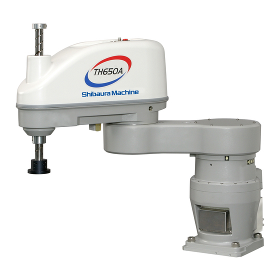
TH650A–IP/TS2100
INSTRUCTION MANUAL
DUST-PROOF & DRIP-PROOF TYPE
INDUSTRIAL ROBOT SPECIFICATIONS
1.
Make sure that this instruction manual is delivered to the final
user of Toshiba Machine's industrial robot.
2.
Before operating the industrial robot, read through and
completely understand this manual.
3.
After reading through this manual, keep it nearby for future
reference.
Notice
November, 2008
TOSHIBA MACHINE CO., LTD.
NUMAZU, JAPAN
STE 80747–1
Advertisement
Table of Contents

Related Manuals for Toshiba TH650A-IP


Summary of Contents for Toshiba TH650A-IP
- Page 1 INDUSTRIAL ROBOT SPECIFICATIONS Notice Make sure that this instruction manual is delivered to the final user of Toshiba Machine’s industrial robot. Before operating the industrial robot, read through and completely understand this manual. After reading through this manual, keep it nearby for future reference.
- Page 2 DUST-PROOF & DRIP-PROOF TYPE SPECIFICATIONS MANUAL Copyright 2008 by Toshiba Machine Co., Ltd. All rights reserved. No part of this document may be reproduced in any form without obtaining prior written permission from Toshiba Machine Co., Ltd. The information contained in this manual is subject to change without prior notice to effect improvements.
- Page 3 DUST-PROOF & DRIP-PROOF TYPE SPECIFICATIONS MANUAL Preface This manual describes the specifications of the TH–A series dust-proof and drip-proof type industrial robot. This manual is essential to keep the robot performance for a long time, to prevent failures and to assure safety. Be sure to look through this manual and set up a maintenance program before actually starting the robot.
- Page 4 DUST-PROOF & DRIP-PROOF TYPE SPECIFICATIONS MANUAL [Explanation of symbols] Symbol Meaning of symbol This means that the action is prohibited (must not be done). Details of the actions actually prohibited are indicated with pictures or words in or near the symbol. This means that the action is mandatory (must be done).
- Page 5 Disassembly prohibited • Always use the Toshiba Machine's designated spare parts when replacing the parts. • Maintenance and inspection should be performed regularly. Otherwise, the system may malfunction or accidents will be Mandatory caused.
- Page 6 DUST-PROOF & DRIP-PROOF TYPE SPECIFICATIONS MANUAL This manual is comprised of the following seven (7) sections: Section 1 Specifications This section describes the basic specifications and names of respective parts for the dust-proof and drip-proof type industrial robot. Section 2 Transportation This section describes how to remove the dust-proof and drip-proof type robot from its box and how to transport it to the installation site.
-
Page 7: Table Of Contents
DUST-PROOF & DRIP-PROOF TYPE SPECIFICATIONS MANUAL Table of Contents Page Specifications ......................9 Name of Each Part ..................9 Outer Dimensions ..................10 Specifications Table..................12 Transportation ......................14 Unpacking......................14 Transportation ....................14 2.2.1 Mass and Outer Dimensions .............15 2.2.2 Transporting the Robot..............16 Installation ......................18 Installation Environment ................18 Ingress Protection (IP) Class of Dust-Proof and Drip-Proof Specifications..19 Air Purge......................20 Coordinate System ..................21... - Page 8 DUST-PROOF & DRIP-PROOF TYPE SPECIFICATIONS MANUAL Page Maintenance ......................34 Layout of Mechanical Components..............34 Maintenance Tools and Preparatory Parts ............35 Replacement Procedures of Bellows .............35 5.3.1 Replacement Procedures of Lower Bellow........35 5.3.2 Replacement Procedures of Upper Bellow........37 Mounting and Dismounting Covers..............39 5.4.1 Base Cover ..................40 5.4.2...
-
Page 9: Specifications
DUST-PROOF & DRIP-PROOF TYPE SPECIFICATIONS MANUAL Specifications Name of Each Part The names of respective parts of the dust-proof and drip-proof type robot are shown in Fig. 1.1 below. Axis 2 Wiring panel Cover (rotation) Bellows Axis 1 (rotation) Arm 2 Bellows Ball screw spline Arm 1... -
Page 10: Outer Dimensions
DUST-PROOF & DRIP-PROOF TYPE SPECIFICATIONS MANUAL Outer Dimensions Fig. 1.2 and Fig. 1.3 show the outer dimensions and operating range of the robot. Wiring panel Space required for cable connection Fig. 1.2 Outer dimensions of the robot STE 80747 – 10 –... - Page 11 DUST-PROOF & DRIP-PROOF TYPE SPECIFICATIONS MANUAL (Axis 1 operating range) (Axis 2 operating range) (Axis 2 operating range) (Axis 1 operating range) Fig. 1.3 Operating range of the robot STE 80747 – 11 –...
-
Page 12: Specifications Table
DUST-PROOF & DRIP-PROOF TYPE SPECIFICATIONS MANUAL Specifications Table Item Specifications Structure Horizontal articulated type SCARA robot Model TH650A–IP Ingress protection (IP) class of IP65 (*1) dust- and drip-proof structure Applicable controller TS2100 (*2) Mass of robot body 53 kg No. of controlled axes Four (4) Arm length 650 mm (300+350) - Page 13 DUST-PROOF & DRIP-PROOF TYPE SPECIFICATIONS MANUAL For details of the ingress protection class, see Paragraph 3.2 (page 9). The robot controller is not constructed to provide dust-proof and drip-proof protection. When the mass of load exceeds 2 kg, or when the gravity center position of load is away from the axis 4 center position, both the speed and acceleration should be reduced, using the PAYLOAD command.
-
Page 14: Transportation
DUST-PROOF & DRIP-PROOF TYPE SPECIFICATIONS MANUAL Transportation Unpacking The robot and controller are shipped separately in wooden crates or corrugated cardboards. Open the packages in a location easily accessible, where the equipment is to be installed. Take careful precautions not to damage the robot and controller. After opening the packages, make sure that all the accessories are present and that no part has been damaged during transport. -
Page 15: Mass And Outer Dimensions
DUST-PROOF & DRIP-PROOF TYPE SPECIFICATIONS MANUAL 2.2.1 Mass and Outer Dimensions The mass and outer dimensions of the robot are shown in Fig. 2.1. Mass of main robot = 53 kg Fixture Fig. 2.1 Outer dimensions during transport STE 80747 –... -
Page 16: Transporting The Robot
DUST-PROOF & DRIP-PROOF TYPE SPECIFICATIONS MANUAL 2.2.2 Transporting the Robot The dust-proof and drip-proof specification robot has dust-proof and drip-proof parts such as bellows, etc. added to the standard robots. The instructions during transport of the robot are listed below. The instructions other than those listed below are the same as those for the standard robots. - Page 17 DUST-PROOF & DRIP-PROOF TYPE SPECIFICATIONS MANUAL CAUTION • When lifting up the robot by workers, hold the shaded locations by hands, as shown in Fig. 2.2. If the ball screw spline shaft is held by hands, an unusually large force is exerted, resulting in a malfunction. •...
-
Page 18: Installation
DUST-PROOF & DRIP-PROOF TYPE SPECIFICATIONS MANUAL Installation Installation Environment Table 3.1 shows the environmental specifications for the robot and controller. Table 3.1 Environmental specifications Item Specifications Temperature In operation 0 to 40°C In storage –10 to 50°C Humidity 20 to 90 % (Non-condensing) Altitude 1000 m or less Vibration... -
Page 19: Ingress Protection (Ip) Class Of Dust-Proof And Drip-Proof Specifications
DUST-PROOF & DRIP-PROOF TYPE SPECIFICATIONS MANUAL Ingress Protection (IP) Class of Dust-Proof and Drip-Proof Specifications The Model TH650A robot (dust-proof and drip-proof specifications) has IP65 or equivalent ingress protect against water and dust. Be sure to perform air purge. Ingress of water and dust cannot be prevented according to some operating environments. -
Page 20: Air Purge
DUST-PROOF & DRIP-PROOF TYPE SPECIFICATIONS MANUAL Air Purge The dust-proof and drip-proof type robot is provided with an air supply port for air purge in its base connector unit. See Fig. 1.1. (Quick-joint with speed controller) Ingress of dust into the interior of the robot can be prevented by supplying air to the air supply port. -
Page 21: Coordinate System
DUST-PROOF & DRIP-PROOF TYPE SPECIFICATIONS MANUAL Coordinate System The robot's joint angle origin (0° or 0 mm position) is factory-calibrated according to the base reference planes. Fig. 3.1 shows the base coordinate system (XB, YB, ZB) and origin of each axis joint angle. Reference plane Reference plane (–) -
Page 22: Installing The Robot
DUST-PROOF & DRIP-PROOF TYPE SPECIFICATIONS MANUAL Installing the Robot The robot is secured in the attachment holes (four places) on the base with M16 hexagonal socket head bolts. The robot installation method is shown in Fig. 3.2. The reference planes are provided on the base section. - Page 23 DUST-PROOF & DRIP-PROOF TYPE SPECIFICATIONS MANUAL Hexagonal socket head bolt Reference plane Reference plane Details of robot attachment hole (4 places) Fig. 3.2 Installation method STE 80747 – 23 –...
-
Page 24: Cable Connection
DUST-PROOF & DRIP-PROOF TYPE SPECIFICATIONS MANUAL Cable Connection The connector layout on the controller side and the connection method are the same as those for the standard robots. Refer to the TH650A Installation and Transportation Manual provided separately. For the dust-proof and drip-proof type robot, the connector on the robot side differs from that of the standard robots. -
Page 25: Connector Terminal Layout
DUST-PROOF & DRIP-PROOF TYPE SPECIFICATIONS MANUAL To connect the connector, make sure of the top and bottom sides of the connector, insert the connector attached to the cable completely into the connector on the robot side, then lock the lever of the connector on the robot side. If the lock is loose, fault is caused by poor contact in the connector. -
Page 26: Tool Interface
DUST-PROOF & DRIP-PROOF TYPE SPECIFICATIONS MANUAL Tool Interface A tool mounting method and tool signals are the same as for the standard robots. For details, refer to the TH650A Installation and Transportation Manual provided separately. Wiring between Tools of the Robot The Model TH650A robot comes with wiring cables for five (5) input signals for sensors, etc. -
Page 27: How To Connect Connectors
DUST-PROOF & DRIP-PROOF TYPE SPECIFICATIONS MANUAL Type of contact: BHF–001T–0.8SS (Maker: J.S.T. Mfg.) Adaptive cable: Conductive cross section area 0.2 mm ~ 0.3 mm Opposite connector type Type of connector: JOEP SMR–07V–B (Maker: J.S.T. Mfg.) JOFP SMR–06V–B (Maker: J.S.T. Mfg.) Type of contact: BYM–001T–0.6 (Maker: J.S.T. - Page 28 DUST-PROOF & DRIP-PROOF TYPE SPECIFICATIONS MANUAL Remove the motor cover of the base. Liquid gasket is applied to the motor cover attachment surface to protect the robot against dust and drip. For the dismantling procedures, see Section 5. Remove the cap of the cable clamp, then the rubber bushing and filler. This filler is unnecessary and is not used any more.
- Page 29 DUST-PROOF & DRIP-PROOF TYPE SPECIFICATIONS MANUAL Input/output signal connector CN0 Signal Input/output circuit Signal name and example of connections Not used User side P24V Not used Not used GRP1 OPN Grip 1 open GRP1 CLS Grip 1 close GRP2 OPN Grip 2 open GRP2 CLS Grip 2 close...
- Page 30 DUST-PROOF & DRIP-PROOF TYPE SPECIFICATIONS MANUAL By using the 24 V DC power supply of the controller, a relay, solenoid valve, etc., can be driven. When using an external power supply, use common GND between the external power supply and the robot controller. Output specifications: Rated voltage 24 V DC (max.
- Page 31 DUST-PROOF & DRIP-PROOF TYPE SPECIFICATIONS MANUAL To robot hand (To be connected by user) Plastic connector for user To PLC (To be connected by user) Fig. 4.3 Wiring between tools of the robot STE 80747 – 31 –...
-
Page 32: Air Pipes Used For Tools Of The Robot
DUST-PROOF & DRIP-PROOF TYPE SPECIFICATIONS MANUAL Air Pipes Used for Tools of the Robot The Model TH650A robot comes with three (3) air line pipes necessary for tools. The outer diameter of the air pipes is 6 mm. Fig. 4.4 shows the air pipe. The user shall prepare solenoid valves and air control unit. - Page 33 DUST-PROOF & DRIP-PROOF TYPE SPECIFICATIONS MANUAL Air joint pitches of the panel Fig. 4.4 Air pipe used for tools STE 80747 – 33 –...
-
Page 34: Maintenance
DUST-PROOF & DRIP-PROOF TYPE SPECIFICATIONS MANUAL Maintenance The basic structure of the dust-proof and drip-proof type robot is the same as that of the standard robots. For the contents of inspection, etc., refer to the TH650A Maintenance Manual provided separately. This section describes the layout of the mechanical components and the procedures for mounting and dismounting the covers and for replacing the upper and lower bellows. -
Page 35: Maintenance Tools And Preparatory Parts
DUST-PROOF & DRIP-PROOF TYPE SPECIFICATIONS MANUAL Maintenance Tools and Preparatory Parts We recommend for the user to prepare tools necessary for maintenance operation and parts that follow. • Screwdrivers (for plus and minus screws) • Hexagonal spanner set M3~M16 • Cutter knife •... - Page 36 DUST-PROOF & DRIP-PROOF TYPE SPECIFICATIONS MANUAL Gasket (attached to inside of bellow) Apply liquid gasket to Gasket the portion (indicated Apply liquid gasket to the by arrow) before portion (indicated by arrow) attaching the bellow. before reattaching the gasket. Retainer (lower) Retainer (upper) Bellow Tool flange...
-
Page 37: Replacement Procedures Of Upper Bellow
DUST-PROOF & DRIP-PROOF TYPE SPECIFICATIONS MANUAL 5.3.2 Replacement Procedures of Upper Bellow 1) Remove three (3) setscrews after having removed the cap and upper bellow, and then remove the wire guide. 2) Remove the lower retainer and pull out the bellow upward. 3) Pull out the bearing case upward to detach the arm 2 cover. - Page 38 DUST-PROOF & DRIP-PROOF TYPE SPECIFICATIONS MANUAL Apply liquid gasket to the portion (indicated by arrow) before attaching the gasket. Bellow shaft Bellow Gasket (adhering Lower retainer to the retainer) Gasket (adhering Upper retainer to the bearing Setscrew case) Setscrew Wire guide Bearing case Apply liquid gasket to the portion (indicated...
-
Page 39: Mounting And Dismounting Covers
DUST-PROOF & DRIP-PROOF TYPE SPECIFICATIONS MANUAL CAUTION • DO NOT pull the bellow by force when removing it. If it is not be done completely, the bellows may be broken. • Be sure to apply Loctite adhesive to the attachment bolts. If you neglect the instruction, the dust-proof and drip-proof performance will be impaired resulting in ingress of water and dust. -
Page 40: Base Cover
DUST-PROOF & DRIP-PROOF TYPE SPECIFICATIONS MANUAL 5.4.1 Base Cover Two type of base cover are available: One is used for connector panel as well; other for battery box as well. The base cover used for the connector panel as well is secured to the base with nine (9) cross-recessed truss head screws (M4x6) and two (2) hexagonal socket head bolts (M4x10) in such a way to surround the gasket. - Page 41 DUST-PROOF & DRIP-PROOF TYPE SPECIFICATIONS MANUAL CAUTION • Be sure to attach the gasket and apply liquid gasket. Also, be sure to coat Loctite adhesives to all attaching bolts. If it is not be done completely, the dust-proof and drip-proof performance will be impaired resulting in ingress of water and dust.
-
Page 42: Arm 1 Cover
DUST-PROOF & DRIP-PROOF TYPE SPECIFICATIONS MANUAL 5.4.2 Arm 1 Cover The arm 1 covers are installed above the axis 1 (arm 1 cover) and under the axis 2 (arm 2 cover). The covers are secured to the arm 1 with six (6) cross-recess truss head screws (M4x6) in such a way to sandwich the gasket between the arm and the cover. -
Page 43: Arm 2 Cover
DUST-PROOF & DRIP-PROOF TYPE SPECIFICATIONS MANUAL When mounting the cover, apply liquid gasket to the area shown in Fig. 5.6 above. After mounting the arm 1 cover, a gap between the arm 1 and the arm 1 cover should be applied with liquid gasket. Also, apply Loctite adhesives to all attaching bolts. CAUTION •... -
Page 44: Cleaning Robot Body
DUST-PROOF & DRIP-PROOF TYPE SPECIFICATIONS MANUAL Though the cover is embedded to the arm 2, liquid gasket is applied to the circumference of the packing under the cover to protect the robot against dust and drip. When detaching the cover, strip off the liquid gasket over the whole surface between the arm 2 and the packing using a cutter or the like. -
Page 45: Lid Used For Arm 2 Panel
DUST-PROOF & DRIP-PROOF TYPE SPECIFICATIONS MANUAL CAUTION • When using a cutter, take careful precautions not to cut the packing body. • DO NOT strip off the liquid gasket between the cover and packing. If it is not be done completely, the dust-proof and drip-proof performance will be impaired resulting in ingress of water and dust. - Page 46 DUST-PROOF & DRIP-PROOF TYPE SPECIFICATIONS MANUAL Arm 2 Gasket Fig. 5.9 Lid used for arm 2 panel CAUTION • Be sure to attach the gasket . Also, be sure to coat Loctite adhesives to all attaching bolts. If it is not be done completely, the dust-proof and drip-proof performance will be impaired resulting in ingress of water and dust.
- Page 47 DUST-PROOF & DRIP-PROOF TYPE SPECIFICATIONS MANUAL Cleaning Robot Body To clean and wash the robot body, be sure to use a neutral detergent. Use a soft sponge and waste cloth, and take careful precautions not to cut or scratch the robot body.
-
Page 48: Maintenance And Replacement Parts
List of Maintenance and Replacement Parts Part name Type Our dwg. No. Unit code Maker Q’ty Remarks Bellows S828912 Y610A38Z0 Toshiba When Z-axis Machine stroke is 200 Bellows S835831 Y610A38Y0 Toshiba When Z-axis Machine stroke is 370 The replacement parts other than the above are the same as those of the TH650A robot. - Page 49 DUST-PROOF & DRIP-PROOF TYPE SPECIFICATIONS MANUAL APPROVED BY: CHECKED BY: PREPARED BY: STE 80747 – 46 – ....