Table of Contents
Advertisement
Quick Links
Advertisement
Table of Contents
Troubleshooting

Related Manuals for Hitachi FSXN Series


Summary of Contents for Hitachi FSXN Series
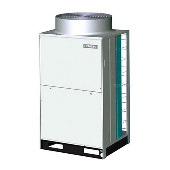
- Page 1 SET FREE SERIES FSXN Service Manual RAS-8FSXN RAS-24FSXN RAS-40FSXN RAS-10FSXN RAS-26FSXN RAS-42FSXN RAS-12FSXN RAS-28FSXN RAS-44FSXN RAS-14FSXN RAS-30FSXN RAS-46FSXN RAS-16FSXN RAS-32FSXN RAS-48FSXN RAS-18FSXN RAS-34FSXN RAS-50FSXN RAS-20FSXN RAS-36FSXN RAS-52FSXN RAS-22FSXN RAS-38FSXN RAS-54FSXN...
- Page 2 Index I n d e x General information Unit installation Piping work and refrigerant charge Electrical wiring Control system Optional functions Test run Troubleshooting Spare parts Servicing Electrical checks of the main parts Maintenance notes SMGB0065 rev. 1 - 12/2010...
-
Page 3: Table Of Contents
Index Index General information..................General information........................1.1.1 Copyright............................. 1.1.2 Introduction..........................1.1.3 Environment-friendly units......................Safety............................1.2.1 Symbols used..........................Product guide..........................1.3.1 Classification of outdoor unit models and CH units..............1.3.2 Product guide: Outdoor units...................... 1.3.3 Accessory code list........................Unit installation....................Outdoor unit..........................2.1.1 Preliminary conditions for positioning of outdoor unit.............. - Page 4 Index 4.1.4 Setting of the DSW switches on PCB1..................4.1.5 Electrical wiring diagram RAS-(8–18)FSXN................CH unit............................4.2.1 General information........................4.2.2 General verifications........................4.2.3 Electrical wiring connection CH units..................Control system....................87 Control system........................... 5.1.1 Cycle control..........................5.1.2 Compressor operation control..................... 5.1.3 Heat exchanger mode control.....................
- Page 5 Index Test run............................137 7.2.1 Before the test run........................137 7.2.2 Test run using the remote control switch..................138 7.2.3 Test run from the outdoor unit..................... 138 7.2.4 Checking at test run........................140 7.2.5 Refrigerant cycle checklist......................141 7.2.6 Automatic judgement system for refrigerant amount..............143 7.2.7 Reset for accumulated operation time of compressor 1-2 after maintenance (cUJ1-cUJ2)..
- Page 6 Index 10.4 Removing the electrical box....................... 295 10.4.1 Removing the electrical box for RAS-(8-12)FSXN..............295 10.4.2 Removing the electrical box for RAS-(14-18)FSXN..............295 10.5 Removing the electrical box stay....................296 10.5.1 Removing the electrical box stay for RAS-(8-12)FSXN.............. 296 10.5.2 Removing the electrical box stay for RAS-(14-18)FSXN............
- Page 7 Index 11.3.5 Thermistor for super cooling bypass and main line temperature of outdoor unit......338 11.4 Electronic expansion valve......................339 11.5 Pressure sensor......................... 340 11.5.1 High pressure control........................340 11.5.2 Low pressure control........................340 11.6 High pressure protection device....................341 11.7 Noise filter (NF1, NF2).......................
- Page 8 1 General information . G e n e r a l i n f o r m a t i o n Index General information........................1.1.1 Copyright............................1.1.2 Introduction........................... 1.1.3 Environment-friendly units......................Safety............................1.2.1 Symbols used..........................Product guide..........................1.3.1 Classification of outdoor unit models and CH units............... 1.3.2 Product guide: Outdoor units......................
-
Page 9: General Information
1.1.2 Introduction HITACHI presents the FSXN series, which belongs to the SET FREE series characterised by its modular design. The application of a single unit, called a base unit (8 - 18 HP) or the combination of two or up to three of these base units of different powers covers the rest of the range of capacities (20 - 54 HP) for air conditioning in office buildings and small industry. -
Page 10: Safety
1 General information 1.2 Safety 1.2.1 Symbols used During normal air conditioning system design work or unit installation, greater attention must be paid in certain situations requiring particular care in order to avoid injuries and damage to the unit, the installation, the building or property. Situations that jeopardise the safety of those in the surrounding area or that put the unit itself at risk will be clearly indicated in this manual. -
Page 11: Product Guide
1 General information 1.3 Product guide 1.3.1 Classification of outdoor unit models and CH units Unit type (outdoor unit): RAS Position-separating hyphen (fixed) Capacity (HP): (8-54) FSX: SET FREE series N: R410A refrigerant – Type of unit: CH (Cooling/Heating Changeover unit) Position-separating hyphen (fixed) Maximum capacity of connectable indoor units (HP) 6.0: 6.0 HP... - Page 12 1 General information ¿ Combination of outdoor units The power range of the RAS-(8-54)FSXN outdoor units is obtained by applying one unit (RAS-(8-18)FSXN) or by the combination of two or three outdoor units (RAS-(20-54)FSXN), depending on the instructions in the following tables. Base units Model RAS-8FSXN...
-
Page 13: Accessory Code List
1 General information 1.3.3 Accessory code list HITACHI offers a range of different accessories and remote control systems that can be used with the SET FREE outdoor units. Please consult the corresponding Technical Catalogue for controls. Name Description Code Figure... -
Page 14: Unit Installation
2 Unit installation . U n i t i n s t a l l a t i o n Index Outdoor unit..........................2.1.1 Preliminary conditions for positioning of outdoor unit..............2.1.2 Transport, lifting and handling of the units..................2.1.3 Installation space RAS-(8-18)FSXN.................... -
Page 15: Outdoor Unit
2 Unit installation 2.1 Outdoor unit 2.1.1 Preliminary conditions for positioning of outdoor unit Mount the outdoor unit in a shady location or where it will not be exposed to direct sunlight, or to high temperatures. It should also be a well-ventilated spot. Mount the outdoor unit so that noises and the discharge of air from the unit will not bother neighbours or the surrounding environment. - Page 16 2 Unit installation ¿ Handling When handling loads with fork-lift trucks, special care should be taken to prevent injury to individuals in the vicinity or damage to the unit itself. C A U T I O N National and local legislation must be observed with respect to driving and the handling of loads with fork-lift trucks.
-
Page 17: Installation Space Ras-(8-18)Fsxn
2 Unit installation 2.1.3 Installation space RAS-(8-18)FSXN > 500 + h2/2 > 300 + h1/2 N O T E Side view. All measurements are in mm. Calculate the service space required during the installation of the unit, based on the following: •... -
Page 18: Center Of Gravity
2 Unit installation 2.1.4 Center of gravity Center of gravity (mm) Outer dimensions (mm) Model Net weight (kg) RAS-8FSXN RAS-10FSXN 1720 RAS-12FSXN RAS-14FSXN RAS-16FSXN 1210 1720 RAS-18FSXN 2.1.5 Installation ¿ Installation with walls in two directions If the units installed are adjacent to high buildings, without walls in two directions, a space of 300 mm is required at the rear side of the unit. - Page 19 2 Unit installation ¿ Installation with walls in three directions Single Installation Installation in the same direction > 300 + h1/2 > 10 > 300 + h1/2 > 10 > 500 > 500 + h2/2 > 20 > 20 > 500 + h2/2 Rear to rear installation 1 Rear to rear installation 2 >...
- Page 20 2 Unit installation ¿ Installation with walls in four directions Single installation Installation in the same direction > 300 + h1/2 > 300 + h1/2 > 200 > 200 > 200 > 200 > 900 > 800 > 500 + h2/2 >...
- Page 21 2 Unit installation ¿ Installation precautions • Avoid installing at locations where strong winds (A) are directed towards the unit's air inlet side (B). If this is not possible, install a wind protector (C). • At locations where snow is frequent, place hoods, field supplied, on the air inlet and outlet areas (B and C) preventing the wind (A) from directly affecting the air outlet.
- Page 22 2 Unit installation ¿ Hood dimensions (field supplied) • The following figures show the recommended dimensions of the air inlet and outlet hoods for the outdoor unit. • Use 1 mm thick steel plates for the hoods and 1.5 mm for the brackets. •...
- Page 23 2 Unit installation RAS-(14-18)FSXN Name Air discharge hood Rear suction hood Left suction hood Right suction hood Safety cable (to prevent overturning) Air flow direction (front side) Air flow direction (rear side) SMGB0065 rev. 1 - 12/2010...
- Page 24 2 Unit installation Enlarge view of A 2 fixing screw. Enlarge view of P Punch Mark (4 places) Drill a pilot hole into the punch mark and mount the fixing plate. Enlarge view of B 2 fixing screw. Enlarge view of C 2 fixing screw.
- Page 25 2 Unit installation Rear suction hood for RAS-(8-12)FSXN <205> Β <933> N O T E C: fixing screw (accessory). D: hole for fixing screw to prevent overturning. < >: dimension of installation. Quantity Name Air discharge hood Suction rear hood Right plate Left plate Front panel (1)
- Page 26 2 Unit installation Rear suction hood for RAS-(14-18)FSXN <205> Α Β <1193> N O T E C: fixing screw (accessory). D: hole for fixing screw to prevent overturning. < >: dimension of installation. Quantity Name Air discharge hood Suction rear hood Right plate Left plate Front panel (1)
-
Page 27: Foundation And Anchorage Of Outdoor Unit
2 Unit installation Right suction hood for RAS-(8-18)FSXN Α Β <360> N O T E C: fixing screw (accessory). D: hole for fixing screw to prevent overturning. < >: dimension of installation. Quantity Name Left suction hood Right suction hood Right plate Left plate Front panel (1) - Page 28 2 Unit installation The foundations must be able to bear the weight of the whole of the base of the unit and should be laid as shown in the diagram. A. Front part of the unit. B. Base of unit. C.
-
Page 29: Units
2 Unit installation 2.2 CH units 2.2.1 Transportation and handling CH units Transport the product as close to the installation location as practical before unpacking. D A N G E R • Do not put any foreign material into the CH unit and check to ensure that none exists in the outdoor unit before the installation and test run. - Page 30 2 Unit installation ¿ Factory supplied accesories Check to ensure that the following accesories are packed with the CH unit. Model CH-6.0N1 Qty. CH-10.0N1 Qty. Reducer ID15.88 ID19.05 ID15.88 ID19.05 ID12.7 ID15.88 Accessory Pipe ID22.2 ID19.05 (for flare nut) ID19.05 ID19.05 ID16 Accessory...
- Page 31 2 Unit installation • Check to ensure that the ceiling is sufficiently strong to sustain the CH unit. If the ceiling is weak, abnormal sound and vibration may occur. • The refrigerant flow sound may be heard from the CH unit when the electric expansion valve in the CH unit is activated. Therefore, take the following action to minimize the sound.
- Page 32 2 Unit installation For steel beam. C-shaped clamp. Antiskid clamp (bend it). Nut. Suspension bolt. Support angle. Suspension bolt. Suspension bolt (W3/8 or M10). I beam. Suspension bolt (W3/8 or M10). For wooden beam suspension. Wooden bar (60 to 90 mm square). Wooden beam.
- Page 33 2 Unit installation Required time is as shown in the following table: Ambient temp. (°C) Time Min. 30 minutes Min. 1 hour Min. 2 hours Min. 4 hours Min. 8 hours SMGB0065 rev. 1 - 12/2010...
- Page 34 2 Unit installation ¿ Installation Changing the location of electrical box Depending on the installation space, changing the location of electrical box is available. In case of changing the location of electrical box, follow the procedure below. Remove the service cover for the electrical box. Remove the service cover for the electronic expansion valve.
- Page 35 2 Unit installation A. Before change. B. After change. * Make sure that the wirings are bounded with the wire clips in order to prevent the electrical box from entering water. Marking of the position of the suspension bolts and wiring connections Mark the positions of the suspension bolts, refrigerant piping connections and wiring connection.
- Page 36 3 Piping work and refrigerant charge . P i p i n g w o r k a n d r e f r i g e r a n t c h a r g e Index Outdoor unit..........................3.1.1 Refrigerant pipe selection......................
-
Page 37: Outdoor Unit
3 Piping work and refrigerant charge 3.1 Outdoor unit 3.1.1 Refrigerant pipe selection The RAS-(8-54)FSXN outdoor units can work as a heat pump system, by means of a two-pipe system (gas pipe and liquid pipe), or they can work as a heat recovery system by means of a three-pipe system (high and low pressure pipes and liquid pipe), requiring in addition the CH units supplied as accessories. - Page 38 3 Piping work and refrigerant charge Select the pipe with the appropriate diameter and thickness. Use the table below to select the most appropriate pipe: Nominal diameter Nominal diameter Thickness mm Supply Thickness mm Supply Inches Inches ø6.35 0.80 Roll ø25.4 1.00 Pipe...
- Page 39 3 Piping work and refrigerant charge ¿ Size of pipes for outdoor unit (2 pipes) Model Liquid (mm) RAS-8FSXN ø19.05 (ø19.05 - ø22.2) ø9.53 (ø9.53 - ø12.7) RAS-10FSXN ø22.2 (ø22.2 - ø25.4) ø9.53 (ø9.53 - ø12.7) RAS-12FSXN ø25.4 (ø25.4 - ø28.6) ø12.7 (ø12.7 - ø15.88) RAS-14FSXN RAS-16FSXN...
-
Page 40: Pipe Connection Kit
3 Piping work and refrigerant charge ¿ Size of pipes for outdoor unit (3 pipes) Model Liquid (mm) Low pressure (mm) High pressure (mm) RAS-8FSXN ø19.05 (ø19.05 - ø22.2) ø15.88 (ø15.88 - ø19.05) ø9.53 (ø9.53 - ø12.7) RAS-10FSXN ø22.2 (ø22.2 - ø25.4) ø19.05 (ø19.05 - ø22.2) ø9.53 (ø9.53 - ø12.7) RAS-12FSXN... - Page 41 3 Piping work and refrigerant charge Dimensions of flared pipe 90º±2 Perform the widening operations in accordance with the measurements shown below. øA Diameters (mm) (mm) -0.4 ø6.35 0.4-0.8R ø9.53 13.2 ø12.7 16.6 ø d ø15.88 19.7 ø19.05 – Not possible to perform the widening using pipe. In this case, use a connection with flare fitting. Selection of the connection with flare fitting It is not possible to perform the widening operation, if copper is used in pipes.
- Page 42 3 Piping work and refrigerant charge Outdoor unit RAS-(8-12)FSXN RAS-(14-18)FSXN ¿ Connection position of outdoor unit pipes Fit and secure refrigerant pipes correctly to prevent vibrations and strain on the stop valves. The pipes may be fitted in three directions (front, rear or inferior) from the base of the unit.
- Page 43 3 Piping work and refrigerant charge only for heat recovery systems. N O T E Please contact your HITACHI distributor if any of the accessories has not been supplied with the unit. 3.1.3 Pipe connection kit ¿ SET FREE FSXN (two pipes) Key: ID: inner diameter.
- Page 44 3 Piping work and refrigerant charge ¿ SET FREE FSXN (three pipes) Key: ID: inner diameter. Quantity: 1. (1): quantity 2. A: towards the outdoor unit. C: towards connection kit 1. OD: outer diameter. All measurements are in mm. B: towards the indoor unit. D: towards connection kit 2.
-
Page 45: Precautions For The Installation Of The Outdoor Unit
3 Piping work and refrigerant charge 3.1.4 Precautions for the installation of the outdoor unit. Order of installation of the units The outdoor units must be installed in decreasing order of capacity: Capacity of unit A ≥ capacity of unit B ≥ capacity of unit C. Unit -A-, with the highest capacity, must be closest the indoor units. -
Page 46: General Instructions On The Installation Of Refrigerant Pipes
3 Piping work and refrigerant charge Place the refrigerant pipes of the outdoor units horizontally, or slightly tilted towards the side of the indoor units to prevent the build-up of refrigerant oil at the lowest point -A-. >500 If the refrigerant pipes are opposite the outdoor unit -A-, there should be a minimum of 500 mm between the outdoor units and the connection kits -B- for maintenance operations. - Page 47 3 Piping work and refrigerant charge ¿ Flared connection mounting Apply a thin layer of oil to the cone opening for refrigeration systems. Line up the end of the flared pipe to face the fitting to which it is to be threaded.
-
Page 48: Refrigerant Pipe Connection For Heat Pump Systems (2 Pipes)
3 Piping work and refrigerant charge ¿ Refrigerant pipe suspension Only suspend the refrigerant pipes at specific points of the building. Whenever possible, avoid suspending them from parts subject to structural movement, e.g. places close to expansion joints or outer walls, etc. - Page 49 3 Piping work and refrigerant charge ¿ Pipe sizes for RAS-(20-36)FSXN (Combination of two units) A: main outdoor unit; B: secondary outdoor unit; C: connection kit; 1: indoor units on left side; 2: indoor units on right side. Install the outdoor units and connect the refrigerant pipes as shown in the diagram. Please refer to the table to determine the appropriate connection kit and the diameter of the pipes for each unit All measurements are in mm.
- Page 50 3 Piping work and refrigerant charge Combination of base units RAS-38 RAS-40 RAS-42 RAS-44 RAS-46 RAS-48 RAS-50 RAS-52 RAS-54 Model FSXN FSXN FSXN FSXN FSXN FSXN FSXN FSXN FSXN RAS-14 RAS-16 RAS-18 RAS-18 RAS-18 RAS-18 RAS-18 RAS-18 RAS-18 Unit A FSXN FSXN FSXN...
- Page 51 3 Piping work and refrigerant charge ¿ Details of the gas and liquid stop valves 1. Gas valve. 2. Liquid valve. A. Plug. Tightening torque 50–58 Nm Liquid 30–42 Nm B. Hexagonal wrench. To open or close the valve. C. Valve. Turn to the left: open; turn to the right: close. Tightening torque Gas, 8-12 HP 18–22 Nm...
- Page 52 3 Piping work and refrigerant charge A. Stop valve (gas, high pressure). F. L-bend (field-supplied) B. Stop valve (liquid). G. Adapter (field-supplied). C. Liquid pipe (field-supplied). H. Accessory pipe. D. Pipe accessory. I. Liquid pipe (field-supplied). E. Gas pipe, high pressure (field-supplied). D A N G E R •...
- Page 53 3 Piping work and refrigerant charge ¿ Example of installation (38 HP: 2 pipes) Connection of front or rear pipes Lower pipe connection A. Gas pipe (field-supplied). E. Accessory for connection of pipes (L-shaped). B. Liquid pipe (field-supplied). F. Outdoor unit 1. C1.
- Page 54 3 Piping work and refrigerant charge 4. Pipe diameter between multikit and indoor unit HP indoor unit Liquid HP indoor unit Liquid (0.8-1.5) ø12.7 ø6.35 ø19.05 ø9.53 ø15.88 ø6.35 10.0 ø22.2 ø9.53 (2.5-5.0) ø15.88 ø9.53 — — — Pipe working conditions Permitted pipe length Part Make...
- Page 55 3 Piping work and refrigerant charge Pipe branching restrictions Follow the instructions given in the table below for pipe installation (field-supplied). Maximum pipe length Main pipe branch Capacity ratio of the between the multikit of the Branch and distributor indoor units after the Pipe length after the Number of main pipe first branch and each...
-
Page 56: Refrigerant Pipe Connection For Heat Recovery Systems (3 Pipes)
3 Piping work and refrigerant charge 3.1.7 Refrigerant pipe connection for heat recovery systems (3 pipes) ¿ Pipe sizes for RAS-(8-18)FSXN (Base unit) All measurements are in mm. RAS-8 RAS-10 RAS-12 RAS-14 RAS-16 RAS-18 Model FSXN FSXN FSXN FSXN FSXN FSXN Gas (low pressure) ø19.05... - Page 57 3 Piping work and refrigerant charge Combination of base units RAS-20 RAS-22 RAS-24 RAS-26 RAS-28 RAS-30 RAS-32 RAS-34 RAS-36 Model FSXN FSXN FSXN FSXN FSXN FSXN FSXN FSXN FSXN RAS-12 RAS-14 RAS-14 RAS-14 RAS-14 RAS-16 RAS-16 RAS-18 RAS-18 Unit A FSXN FSXN FSXN...
- Page 58 3 Piping work and refrigerant charge Combination of base units RAS-38 RAS-40 RAS-42 RAS-44 RAS-46 RAS-48 RAS-50 RAS-52 RAS-54 Model FSXN FSXN FSXN FSXN FSXN FSXN FSXN FSXN FSXN RAS-14 RAS-16 RAS-18 RAS-18 RAS-18 RAS-18 RAS-18 RAS-18 RAS-18 Unit A FSXN FSXN FSXN...
- Page 59 3 Piping work and refrigerant charge ¿ Gas stop valve Check that the high pressure valves -A- and low pressure valves -J- are completely closed. Connect the charge pipe to the stop valves -B- and release gas from the high pressure pipe -C- and low pressure pipe -I-. Cut off the end -D- of the stop pipe -E- (ø6.35) and check that there is no gas in the high and low pressure gas pipe.
- Page 60 3 Piping work and refrigerant charge P. Refrigerant gas/liquid pressure. C A U T I O N • Do not force the valve open buffer; this could damage the seat of the valve. A spare valve seat is not supplied. •...
- Page 61 3 Piping work and refrigerant charge ¿ Pipe connection kit (optional) Application in outdoor units Mode Model Notes Outdoor unit No. of outdoor units RAS- MC-20XN (20-24)FSXN For three pipes: RAS- • Gas, high pressure: 1 part. Pipe connection kit Heat recovery system MC-21XN (26-36)FSXN...
- Page 62 3 Piping work and refrigerant charge 2. Diameter of the main pipe (from the base unit or connection kit 1 to the first branch) (3 pipes) Gas, low Gas, high HP outdoor Gas, low Gas, high HP outdoor unit Liquid Liquid pressure pressure...
- Page 63 3 Piping work and refrigerant charge Pipe working conditions (13) Permitted pipe length Part Make ≤ Recommended number ≥ Recommended number of connected indoor units of connected indoor units Current total liquid pipe ≤ 1000 m ≤ 300 m (14) Total pipe length length ≤...
- Page 64 3 Piping work and refrigerant charge (12) • For operations in refrigeration mode only, connect the indoor units using gas and liquid pipes (without the CH unit). The total capacity in refrigeration mode only must be less than 50% the total capacity of the indoor units.
-
Page 65: Refrigerant Charge
3 Piping work and refrigerant charge Figure 2: capacity ratio of the indoor units ≤ 40% Figure 1: two branches on the main pipe 41 - 90 m 41 - 90 m A: main branch A: main branch B: secondary branch Figure 3: distributor used as branching for three pipes and Figure 4: do not connect a branch to a distributor branching for two pipes... - Page 66 3 Piping work and refrigerant charge Check the suspension of the refrigerant pipes as described in chapter Refrigerant pipe suspension, see on page 41. 1. Heat pump system. G. Vacuum pump. 2. Heat recovery system. H. Refrigerant gas pipe, high pressure. A.
- Page 67 3 Piping work and refrigerant charge Check that the pressure reading on the indicators remains stable for an hour or more. If this is not the case, check there are no refrigerant leaks at the welds and the flared connections of all the system. N O T E If the maximum pressure of -0.1 MPa (-756 mmHg) or less is not obtained, and there are no leaks, keep the vacuum pump running for one or two hours.
- Page 68 3 Piping work and refrigerant charge W2: additional refrigerant charge per indoor unit No of indoor units of 8 and 10 HP Amount of refrigerant per unit Additional refrigerant charge (kg) x 1.0 kg/unit ______ kg N O T E It is not necessary to increase the additional refrigerant charge for indoor units with less than 8 HP.
- Page 69 3 Piping work and refrigerant charge Connect the power supply to the indoor and outdoor units in the same refrigeration cycle for the function to automatically estimate the amount of refrigerant charged in the unit. N O T E • This function is applicable when the outdoor temperature range is between 0 and 43 °C DB (DB: dry bulb) and the indoor temperature is between 10 and 32 °C DB (DB: dry bulb).
-
Page 70: Precautions In The Event Of Refrigerant Leaks
3 Piping work and refrigerant charge Turn the DSW5 contact number four (on PCB1) to OFF when the refrigerant charge is sufficient. Wait at least three minutes before turning the DSW5 contact number four (on PCB1) to OFF so that the outdoor unit is ready to start operating. N O T E •... -
Page 71: Drainage Pipes
3 Piping work and refrigerant charge ¿ Countermeasures in the event of refrigerant leaks The room should have the following characteristics in case of a leak of refrigerant: Opening without shutter to permit the circulation of fresh air in the room. Opening without door measuring 0.15%, or greater, of the floor surface. - Page 72 3 Piping work and refrigerant charge ¿ Installation position of the optional drainage kit DBS-TP10A Installation position (example: RAS-10FSXN, lower and side views). A. Drain pipe. C. Drain pipes (field-supplied). B. Optional drain plug. D. Base of unit. Drain kit components Model Description Material/colour...
-
Page 73: Unit
3 Piping work and refrigerant charge 3.2 CH unit 3.2.1 Considerations D A N G E R • Use refrigerant R410A in the refrigerant cycle. Do not charge oxygen, acetylene or other flammable and poisonous gases into the refrigerant cycle when performing a leakage test or an air-tight test. These types of gases are extremely dangerous and can cause an explosion. -
Page 74: Refrigerant Piping Work
3 Piping work and refrigerant charge Required tightening torque Pipe size Tightening torque ø6.35 14 ~ 18 N-m ø9.53 34 ~ 42 N-m ø12.7 49 ~ 61 N-m ø15.88 68 ~ 82 N-m ø19.05 100 ~ 120 N-m C A U T I O N •... - Page 75 3 Piping work and refrigerant charge Table 1 Connected indoor unit capacity and piping size. Connected indoor Unit Low pressure gas pipe High pressure gas pipe Model Gas pipe (mm) capacity (HP) (mm) (mm) 0.8 ~ 1.5 ø15.88 ø12.7 ø12.7 * CH-6.0N1 1.6 ~ 4.0 ø15.88...
- Page 76 3 Piping work and refrigerant charge CH: CH Unit. Item Allowable piping length CH-6.0N1 within 30 m Total piping length between CH unit and indoor unit L a+b+c CH-10.0N1 within 10 m Height difference between indoor units connected to the same CH unit within 4 m Height difference between CH units within 15 m...
- Page 77 3 Piping work and refrigerant charge ¿ Piping insulation (ID38) (ID38) CH Unit (ID16) CH-6.0N1 (ID16) (ID38) (ID43) (ID22) (ID43) CH Unit CH-10.0N1 (ID20) (ID22) (ID43) Insulation. Clamp. (Upper surface). ID: Inner diameter. N O T E • In case that the humidity inside the ceiling is high, apply additional insulation to the flare nut connection. •...
- Page 78 4 Electrical wiring . E l e c t r i c a l w i r i n g Index Outdoor unit..........................4.1.1 General information........................4.1.2 General verifications........................4.1.3 Connection of the power supply circuits..................4.1.4 Setting of the DSW switches on PCB1..................4.1.5 Electrical wiring diagram RAS-(8–18)FSXN..................
-
Page 79: Electrical Wiring
4 Electrical wiring 4.1 Outdoor unit 4.1.1 General information C A U T I O N • Before any work to the electrical wiring or regular inspections, switch off the mains power supply of the indoor and outdoor units. Wait three minutes before starting installation or maintenance work. •... -
Page 80: Connection Of The Power Supply Circuits
Standard EN60 335-1. The cross-sections of the cable have been selected for the maximum current of the unit, in accordance with MLFC cable (Flame Retardant Polyflex Wire) manufactured by HITACHI Cable Ltd., Japan. N O T E Do not use cables that are lighter than the normal flexible coated polychloroprene cable (code H05RN-F). - Page 81 4 Electrical wiring Voltage imbalance Up to 3% in each phase, measured at the main terminal of the outdoor unit. Electromagnetic compatibility According to Directive 2004/108/EC (89/336/EEC) regarding electromagnetic compatibility, the following table indicates: the maximum allowed impedance Z of the system at the connection point of the user's power supply, as per EN 61000-3-11.
- Page 82 4 Electrical wiring Connect the three-phase power cables on terminals L1, L2, L3 and N of the TB1 -A- terminal board and connect the earth wire to the screw-in terminal -B-. Use insulated terminals or heat-shrink covers. D: harness lifter for fixing the transmission wiring (2 places). Connect the communication cables on the terminals of the TB2 -C- of the PCB1: •...
- Page 83 4 Electrical wiring Connect the communication cable on the corresponding units to the same refrigerant cycle. (Where the refrigerant pipe of the indoor unit is connected to the outdoor unit, connect the communication cable to the same indoor unit). N O T E Connecting the refrigerant pipe and the communication cable to units in different refrigerant cycles may lead to operating problems.
- Page 84 4 Electrical wiring Connection diagram: heat pump system L1 L2 L3 N 1 2 3 4 L1 L2 L3 N 1 2 3 4 400V/50Hz 400V/50Hz L1 L2 N L1 L2 N 220-240V/50Hz 1 2 A B 1 2 A B 230V/50Hz Main outdoor unit Secondary outdoor unit...
-
Page 85: Setting Of The Dsw Switches On Pcb1
4 Electrical wiring Connection diagram: heat recovery system Main outdoor unit Secondary outdoor unit Operation wiring (shielded twisted pair cable or shielded pair cable) 5 Vdc non-polar H-LINK (field-supplied) Distribution box (field-supplied) Indoor units Operation wiring (shielded twisted pair cable or shielded pair cable) (field-supplied) Fuse (field-supplied) PC-ART remote control Indoor unit system No 0... - Page 86 4 Electrical wiring N O T E • Only the DIP DSW1, DSW2 and DSW4 switches can be set while the voltage supply is connected. • The symbol “■” indicates the position of the DIP switches. The figures show the position of the DIP switch once the position setting has been completed.
- Page 87 4 Electrical wiring DSW5: emergency operation /test run and service setting Setting not required. Activate only when the following functions are used: • Contact 1: except No 1, compressor operation. • Contact 2: except No 2, compressor operation. • Contact 4: Monitoring of refrigerant quantity. DSW6: setting outdoor unit number Setting required.
- Page 88 4 Electrical wiring DSW10: switch setting example DSW10 DSW10 DSW10 DSW10 DSW10 DSW10 DSW10 H-LINK H-LINK II H-LINK H-LINK H-LINK II H-LINK II H-LINK H-LINK II A. Main unit. D. Indoor units. B. Secondary unit. E. Remote control. C. Secondary unit. N O T E •...
-
Page 89: Electrical Wiring Diagram Ras-(8-18)Fsxn
4 Electrical wiring 4.1.5 Electrical wiring diagram RAS-(8–18)FSXN SMGB0065 rev. 1 - 12/2010... -
Page 90: Unit
4 Electrical wiring 4.2 CH unit 4.2.1 General information D A N G E R • Turn OFF the main power switch to the CH unit, the indoor unit and the outdoor unit before electrical wiring work or a periodical check is performed. •... - Page 91 The wire sizes marked with in the above table are selected at the maximum current of the unit according to the wire, MLFC (Flame Retardant Polyflex Wire) manufactured by Hitachi Cable Ltd., Japan. • Use a shielded cable for the transmitting circuit and connect it to ground.
- Page 92 4 Electrical wiring ¿ Example of electrical wiring The following figure shows the example of electrical wiring around the CH units. Refer to the Technical Catalog for Outdoor Unit regarding the electrical wiring of the whole system. AC 1~ 220-240V/50Hz CH Unit CH Unit A: Outdoor unit power supply.
- Page 93 4 Electrical wiring DSW1 DSW101 SW301 C A U T I O N • The control of the temperature is only available through the room’s thermostat or Aquastat. The Remote Control Switch of the indoor unit cannot be touch, if it is done the unit will be outside of warranty. •...
- Page 94 5 Control system . C o n t r o l s y s t e m Index Control system........................... 5.1.1 Cycle control..........................5.1.2 Compressor operation control....................... 5.1.3 Heat exchanger mode control....................... 5.1.4 Outline of the control system......................Standard operation sequence....................5.2.1 Cooling operation..........................
-
Page 95: Control System
5 Control system 5.1 Control system 5.1.1 Cycle control Heating Cooling Defrost Heat recovery Control device Purpose Contents Purpose Contents Contents Capacity control is Total operation carried out to reach Total operation PI control is carried All the Compressor capacity of the the evaporation capacity of the out to reach the... -
Page 96: Compressor Operation Control
5 Control system Heating Cooling Defrost Heat recovery Control device Purpose Contents Purpose Contents Contents Shut-off of high Compressor Shut-off of high Compressor High and low and low pressure operating: ON and low pressure operating: ON pressure shut-off Open in the cycle during Compressor in the cycle during Compressor... - Page 97 5 Control system RAS-(28-36)FSXN Outdoor unit 1 Outdoor unit 2 Last time Currently Next time Inverter compressor Constant compressor RAS-(38-42)FSXN Outdoor unit 1 Outdoor unit 2 Outdoor unit 3 Last time Currently Next time Inverter compressor Constant compressor RAS-(44-48)FSXN Outdoor unit Outdoor unit 1 Outdoor unit 2 Last time...
- Page 98 5 Control system RAS-(14-18)FSXN (Power supply frequency: 50 Hz) A. Compressor operation condition. B. Frequency of Inverter compressor (Hz). C. Target frequency (Hz). D. Inverter compressor. E. Inverter compressor + constant compressor. RAS-20FSXN (Power supply frequency: 50 Hz) A. Compressor operation condition. B.
- Page 99 5 Control system RAS-(28-36)FSXN (Power supply frequency: 50 Hz) A. Compressor operation condition. B. Frequency of Inverter compressor (Hz). C. Target frequency (Hz). D. Inverter compressor. E. Two Inverter compressors. F. Two Inverter compressors + constant compressor. G. Two Inverter compressors + two constant compressors. Objective frequency (Hz) RAS-(38-42)FSXN (Power supply frequency: 50 Hz) A.
- Page 100 5 Control system C. Target frequency (Hz). D. Inverter compressor. E. Two Inverter compressors. F. Three Inverter compressors. G. Three Inverter compressors + constant compressor. H. Three Inverter compressors + two constant compressors. Objective frequency (Hz) RAS-(50-54)FSXN (Power supply frequency: 50 Hz) A.
-
Page 101: Heat Exchanger Mode Control
5 Control system 5.1.3 Heat exchanger mode control • Heat recovery system: in accordance with the connected load of indoor units, the outdoor unit heat exchanger can switch as indicated in the following table. • Heat pump system: in accordance with the operation mode of the indoor units, the outdoor unit heat exchanger can switch as indicated in the following table. -
Page 102: Outline Of The Control System
5 Control system The number of outdoor unit: 3 Heating Cooling mode Mainly cooling mode Mainly heating mode Defrost mode mode Heat exchanger mode DEF2 DEF1 COND D2-1 D2-2 D2-3 D3-1 D3-2 EVAP With CH unit Without CH unit Heat exchanger COND COND COND... - Page 103 5 Control system Symbol Description DC motor (for Inverter compressor) AC motor (for constant speed compressor) DC motor (for outdoor unit fan) Motor (for the indoor unit fan) Motor (for the automatic louver) Motor (for the drain pump) Electronic expansion valve (for the indoor unit) Electronic expansion valve (for the outdoor unit) Electronic expansion valve (for the plate heat exchanger) Magnetic contactor for the compressor...
-
Page 104: Standard Operation Sequence
5 Control system 5.2 Standard operation sequence 5.2.1 Cooling operation I.U.: Indoor Unit O.U.: Outdoor Unit Auto - louver only for Indoor Unit 0 Reset with Auto-Louver Start of Transmitting between Power to Power to PCB I.U. and O.U. I.U.: ON in I.U.: ON Start of Transmitting between I.U. -
Page 105: Cooling Operation (Continued)
5 Control system 5.2.2 Cooling operation (continued) I.U.: Indoor Unit Start of Auto-Louver Pressing only for Air Panel Alternately AUTO-LOUVER or Indoor Unit Switch with Auto-Louver Stop of Auto-Louver Pressing RUN/STOP Switch After 3 min. MD Stop 20 sec. for Unit with Drain Pump Power to MIF : OFF RUN/STOP Lamp: OFF, COOL, Set Fan Speed... -
Page 106: Dry Operation
5 Control system 5.2.3 Dry operation I.U.: Indoor Unit O.U.: Outdoor Unit Auto - louver only for Indoor Unit 0 Reset with Auto-Louver Start of Transmitting between Power to PCB I.U. and O.U. Power to in I.U.: ON Start of Transmitting between I.U.: ON I.U. -
Page 107: Dry Operation (Continued)
5 Control system 5.2.4 Dry operation (continued) I.U.: Indoor Unit Start of Auto-Louver Pressing only for Air Panel Alternately AUTO-LOUVER or Indoor Unit Switch with Auto-Louver Stop of Auto-Louver Pressing RUN/STOP Switch After 3 min. MD Stop 20 sec. for Unit with Drain Pump Power to MIF : OFF RUN/STOP Lamp: OFF, COOL, Set Fan Speed... -
Page 108: Antifreeze Protection Control During The Cooling Or Dry Operation
5 Control system 5.2.5 Antifreeze protection control during the cooling or dry operation Power Supply Cooling Operation or Dry Operation Is compressor operated for more than *30 min.? * The judging time varies under the condition. Cooling Operation or Dry Operation Pipe Surface Temp. -
Page 109: Heating Operation
5 Control system 5.2.6 Heating operation I.U.: Indoor Unit O.U.: Outdoor Unit Start of Transmitting between Power to Power to PCB I.U. and O.U. Start of I.U.: ON in I.U.: ON Transmitting between I.U. and Remote Control Switch only for Indoor Unit Auto - louver 0 Reset with Auto-Louver... -
Page 110: Heating Operation (Continued)
5 Control system 5.2.7 Heating operation (continued) I.U.: Indoor Unit O.U. Outdoor Unit Start of Auto-Louver Pressing only for Air Panel Auto-Louver Alternately or Indoor Unit Switch with Auto-Louver Stop of Auto-Louver Pressing RUN/STOP Indoor < 50°C Switch Unit Discharge Indoor Fan Motor MIF : OFF Air Temp. -
Page 111: Defrost Operation
5 Control system 5.2.8 Defrost operation Heating Small Temperature Difference Heating Operation Time between Outdoor Temperature 40 Minutes or Above and Evaporating Temperature (Te) at Heat Exchanger Defrosting RVR1 : ON RVR2 : OFF Outdoor FAN MOF1 : OFF 1 Minute Later Compressor Operating High Frequency at Low Frequency... -
Page 112: Excessive High Discharge Air Temperature Prevention Control
5 Control system Temperature conditions under defrosting operation: A: Outdoor evaporating temperature °C. B: Defrost operation stop area. C: Outdoor temperature °C. D: Defrost operation start area. 5.2.9 Excessive high discharge air temperature prevention control (only for RCI, RCD and RPI (≤... -
Page 113: Protection Control
5 Control system 5.2.10 Protection control ¿ Pressure ratio increase protection control The pressure ratio increase protection control is carried out for the whole outdoor units to be connected. N O T E In the case of base unit combinations, the control of the figure is carried out for connecting each outdoor unit. In order to carry out this control, the pressure ratio of each outdoor unit is calculated and the maximum value is used. - Page 114 5 Control system ¿ Inverter current protection control The Inverter current protection control is carried out to prevent the damage of the inverter caused by the increase of inverter secondary current value. N O T E In the case of base unit combinations, the control of the figure is carried out for the whole outdoor units to be connected.
- Page 115 5 Control system ¿ Discharge temperature increase protection control The discharge temperature increase protection control is carried out to protect the compressor motor coil from a discharge pressure increase during an anomaly. N O T E In the case of base unit combinations, the control of the figure is carried out for the whole outdoor units to be connected.
-
Page 116: Control Of Ch Unit (Ch-(6.0/10.0)N1)
5 Control system (4) Inverter fin temperature increase protection control. (5) Discharge temperature increase protection control. (6) Discharge gas superheat decrease protection control. Example of discharge temperature increase protection control: A. Normal operation. B. Forced decrease in frequency (1.0 Hz/s). C. - Page 117 5 Control system Expansion valve Number Condition Signal Opening (Pulse) LED4 MVD2 LED5 MVD1 LED6 MVS2 LED7 MVS1 (a) When Outdoor Unit Compressor is Stopped (All Indoor Unit are Stopped). Refer to the table below for the expansion valve opening of CH unit when all the indoor units are stopped (including thermo- OFF stoppage).
-
Page 118: Control And Safety Devices
5 Control system 5.3 Control and safety devices 5.3.1 Outdoor unit Compressor protection The compressor is protected by the following devices and their combinations: 1. Pressure switch: this switch stops the compressor when the discharge pressure exceeds the set value. 2. - Page 119 6 Optional functions . O p t i o n a l f u n c t i o n s Index Setting method........................... External input and output setting....................6.2.1 External input function setting....................... 116 6.2.2 External output function setting..................... 120 Function setting..........................
-
Page 120: Setting Method
6 Optional functions 6.1 Setting method Setting PSW of the outdoor unit PCB is required for setting External input and output setting, see on page 115, -A- and Function setting, see on page 123, -B- (*). N O T E (*) In case of 20 to 54 HP, set from the PSW in outdoor unit A (setting from the PSW in outdoor unit B and C is valid). - Page 121 6 Optional functions 6.2 External input and output setting The outdoor unit PCB has three input terminals (CN17, CN18) that receive external signals and two output terminals (CN16) that send signals to the exterior. The control functions are available by setting input and output terminals as shown below: Control function number Setting of input functions Fixing the heating mode...
-
Page 122: External Input Function Setting
6 Optional functions Setting Mode If the inicial setting has to be modified, the following instructions must be followed: 1 Selecting “External Input and Output Setting” it will be displayed on the 7-segment display. (The setting must be carried out during the stoppage of the outdoor unit. Also, the DSW4-#4 switch of the outdoor unit PCB must be set to “ON” before the modification in order to prevent activation of the compressor). - Page 123 6 Optional functions Specifications for the main component requirements: Components Specifications Remarks Mini power relay, MY1F (or MY2F) Auxiliary relay (X1, X2) 220/240 V made by OMRON Changeover switch (SS2, SS3) Manual switch 220/240 V PCC-1A (connected to a JST, 5 cables with connectors in a single 3-pin connector cable XARP-3 connector)
- Page 124 6 Optional functions ¿ Demand stoppage (Control function number 3) • When the input terminals for the outdoor unit PCB1 demand stoppage are short-circuited, the compressor or compressors will be stopped. In this case, the indoor units will be under Thermo-OFF condition. In cooling mode: air flow setting, heating mode: Lo setting.
- Page 125 6 Optional functions ¿ Forced stoppage (Control function number 5) • When the outdoor unit PBC1 input terminals for the forced stoppage are short-circuited during running the compressor and the indoor unit fans are stopped. However, the remote control screen remains in the same number 10 stoppage code.
-
Page 126: External Output Function Setting
6 Optional functions The sound operation can be adjusted by selecting the control function number. Outdoor unit capacity (specification Control function number Operating sound (targeted value) ratio) No setting Catalogue value 100% 11 (Low noise level setting 1) Catalogue value -2 dB(A) 12 (Low noise level setting 2) Catalogue value -5 dB(A) 13 (Low noise level setting 3) - Page 127 6 Optional functions Specification for the main component requirements: Components Specifications Remarks High power relay, LY2F DC 12 V Auxiliary relay (*) — made by OMRON PCC-1A (connected to a JST, 5 cables with connectors in a single 3-pin connector cable XARP-3 connector) assembly Low voltage...
- Page 128 6 Optional functions Auxiliary relay 3-pin connector Connector CN16 Outdoor unit PCB1 1 2 3 CN16 ¿ Defrosting signal (Control function number 4) This function is used to receive the defrosting signal. • The auxiliary contact relay (RYa) is closed during defrosting. •...
-
Page 129: Function Setting
6 Optional functions 6.3 Function setting This setting must be carried out during stoppage of the outdoor unit. Set DSW4-#4 of the outdoor unit PCB to ON position before performing in order to prevent the compressor from being activated. Press PSW1 for more than 3 seconds. ”Menu”... - Page 130 6 Optional functions Function No. Input Output Demand current control 60% Demand current control 70% Demand current control 80% Demand current control 100% Low noise setting 1 Low noise setting 2 Low noise setting 3 No setting No setting The same input/output function can not be set to different input/putput terminals. If set, a setting of larger function number is became incalid.
- Page 131 6 Optional functions Item SEG2 SEG1 Not Prepared F Adjustment of Fan Rotation (for multiple installation) Not Prepared L Not Prepared Not Prepared Not Prepared End of setting: - Press PSW1 for more than 3 seconds. The display indication change to normal indication. - Turn OFF DSW4-#4.
- Page 132 6 Optional functions Function Setting from the outdoor unit PCB Start Press PSW1 more than 3 seconds. The “Menu” is indicated on the 7-Segment Display. Menu PSW1 SEG2 SEG1 PSW1 to Check Mode More Than 3 Seconds to END of Setting PSW4 PSW2 PSW4...
- Page 133 6 Optional functions PSW4 PSW2 Low Noise Setting PSW4 PSW2 Not Available Cold Draft Not Available PSW3 PSW5 Protection PSW3 PSW5 Available Available PSW3 PSW5 PSW3 PSW5 Available Available PSW3 PSW5 PSW3 PSW5 Available Available PSW3 PSW5 Available PSW4 PSW2 PSW3 PSW5 Not Prepared...
- Page 134 6 Optional functions Function setting 7-segment display Setting item Contents SEG2 SEG1 No setting Indoor unit fan control during the Forced connection and disconnection on the indoor unit fan (2 minutes ON / 6 Thermo-OFF in heating mode minutes OFF). No setting Night-shift Setting of night-shift...
- Page 135 6 Optional functions 7-segment display Setting item Contents SEG2 SEG1 Initial setting (Targeted value of the SH +5 °C) SH targeted value 7 SH targeted value 6 Target value of the Indoor unit expansion valve control for cooling SH targeted value 4 SH targeted value 3 05-09 Not prepared (If set, the setting item will be ignored by the control PCB)
-
Page 136: Indoor Unit Fan Control During The Thermo-Off In Heating Mode
6 Optional functions 7-segment display Setting item Contents SEG2 SEG1 Initial setting Maximum fan rotation limit 20 steps Maximum fan rotation limit 18 steps Maximum fan rotation limit 16 steps Low noise setting (in the case of low Frequency limit 1 noise setting, the working range in Frequency limit 2 cooling/heating will be restricted) -
Page 137: Night-Shift (Low Noise)
6 Optional functions N O T E When the indoor unit fan is stopped due to another control, it is not available to operate the indoor fan. 6.3.2 Night-shift (Low noise) Press PSW3 and select the setting for condition “1” of the night shift (low noise) “ni” consequently, the function can be set. The outdoor fan operation is controlled by the fan controller, with the sequence shown in the picture. -
Page 138: Cancellation Of The Outdoor Ambient Temperature Limit
6 Optional functions Converted frequency of constant speed compressor Power supply frequency (Hz) Outdoor unit capacity (HP) 14,16 N O T E The maximum frequency for the 8 to 18 HP outdoor units is indicated as: Inverter frequency + converted frequency of constant speed compressor. -
Page 139: Defrost For Cold Area (Change Of Defrost Condition)
6 Optional functions 6.3.4 Defrost for cold area (change of defrost condition) Press PSW3 and select the setting for condition “1” at the defrost for the cold area “Jo” . Standard specifications Cold area specifications Setting condition When change of defrost condition is not set When change of defrost condition is set Temperature conditions under defrosting operation... -
Page 140: Wave Function Setting
6 Optional functions Demand control Adapting the self-demand function, which causes the power consumption to drop drastically for the purpose of saving energy. Excessive power supply consumption exceeding the power setting range is restricted. Power Setting Selectable from 100%, 80%, 70%, 60% and 40% of the Maximum efficiency is secured rated power consumption for... - Page 141 7 Test run . T e s t r u n Index Preliminary checks........................Test run............................7.2.1 Before the test run......................... 137 7.2.2 Test run using the remote control switch..................138 7.2.3 Test run from the outdoor unit....................... 138 7.2.4 Checking at test run........................
-
Page 142: Preliminary Checks
7 Test run 7.1 Preliminary checks The test run must be performed according to the instructions in section Test run. D A N G E R Do not use the system until all the checkpoints have been verified. As with the test run for the indoor unit, check the Installation and maintenance manual for the indoor unit and the CH unit. -
Page 143: Test Run
7 Test run 7.2 Test run 7.2.1 Before the test run C A U T I O N • Disconnect all the power supply switches. • Use a multimeter and check that all the switches are disconnected. Before carrying out the test run, check that the unit is properly installed in accordance with the Installation and Operation Manual. -
Page 144: Test Run Using The Remote Control Switch
7 Test run 7.2.2 Test run using the remote control switch Turn ON the power source of the indoor and outdoor units. Set the TEST RUN mode by the remote control switch. Counting Number of Connected Units Depress the "MODE" and the "CHECK" switches HIGH SET TEMP. - Page 145 7 Test run Setting of DIP switch (before shipment): DSW4 Switch for setting of service operation and fuction Test run COOL / HEAT setting (ON: heating mode) OFF (fixed) Manual compressor OFF OFF (fixed) OFF (fixed) D A N G E R •...
-
Page 146: Checking At Test Run
7 Test run (a) Cooling (b) Heating (1) During the operational test, the following fault indication may appear. (2) If the remote control has been set to a different mode, the test run function will not start. In this case, carry out the following actions before the test run. -
Page 147: Refrigerant Cycle Checklist
7 Test run (a) The high pressure will increase when the following procedure is carried out. Cover the air inlet of the outdoor unit during the Cover the air inlet of the indoor unit during the cooling operation heating operation. (b) When the high pressure retry control is activated, the alarm code will be indicated "P13"... - Page 148 7 Test run b. Data samples (cooling/heating, indoor temperature 21 – 30 °C) Check item Result Check the operating data after it has been operating for 20 minutes. Check Pd and Td. IsTd-SH between 15 and 45 degrees? Is Ps between 0.2 and 1.1 MPa? Is Pd between 1.0 and 3.5 MPa? (If the outdoor temperature is high, Pd becomes high).
-
Page 149: Automatic Judgement System For Refrigerant Amount
7 Test run b. Heating operation (this is applicable when the outdoor temperature is higher than 0 °C). Check item Standard Causes Result Are oE1 and oE2 (opening of the outdoor unit • Low: excessive refrigerant. expansion valves) abnormally low or high when —... - Page 150 7 Test run DSW5-4 < Procedure of refrigerant amount check operation > (1) Check that the power supply to all the indoor units is disconnected. (2) Place contact 4 of DSW5 (on PCB1 of the main outdoor unit) to 1 2 3 4 5 6 the ON position as shown in the picture.
-
Page 151: Reset For Accumulated Operation Time Of Compressor 1-2 After Maintenance (Cuj1-Cuj2)
7 Test run 7–segment indication Result Indications The refrigerant amount is sufficient. Sufficient refrigerant • Place contact number 4 of DSW5 (on PCB1) to OFF and carry out the test run. The refrigerant amount is excessive. • Calculate the refrigerant charge according to the length of the refrigerant pipes. Excessive refrigerant •... -
Page 152: Test Run Check List
7 Test run 7.2.8 Test run check list MODEL: SERIAL No.: COMPRESSOR MFG No.: NAME AND CUSTOMER ADDRESS: DATE: Does the indoor unit fan rotation in the correct direction? __________ Does the outdoor unit fan rotation in the correct direction? __________ Can you hear strange noises in the compressor? Has the unit been operating for at least twenty (20) minutes? __________ Check the temperature of the room:... - Page 153 8 Troubleshooting . T r o u b l e s h o o t i n g Index Initial troubleshooting......................... 8.1.1 Checking the electrical wires and the power source ..............148 8.1.2 Checking by 7-segment display....................149 8.1.3 Checking of the alarm code history....................150 8.1.4 Emergency operation........................
-
Page 154: Initial Troubleshooting
8 Troubleshooting 8.1 Initial troubleshooting 8.1.1 Checking the electrical wires and the power source Item to check Check method Is the power source breaker or the Check the voltage (secondary side) of the breaker and using a multimeter, fuse blown? check the continuity of the fuse. -
Page 155: Checking By 7-Segment Display
8 Troubleshooting 8.1.2 Checking by 7-segment display • Simple Checking by 7-Segment Display Display Turn on All Indoor Units All the Indoor Units Connected to the Outdoor Unit Turn on the Outdoor Unit Auto-addressing Starts During auto-addressing, the following items can be checked using the outdoor unit's on-board 7-segment LED display. -
Page 156: Checking Of The Alarm Code History
8 Troubleshooting 8.1.3 Checking of the alarm code history Alarm code history is indicated in the following order while the check mode is displayed. “no01” (latest) history data ~ “no15” (oldest) history data Refer to the figure below as an example. PSW1 PSW2(▲) History is displayed up to 15 cases at the maximum... - Page 157 8 Troubleshooting ¿ Alarm code history record Alarm code history indication Cause of stoppage Alarm code Alarm code or Contents (alarm code or Time Alarm stoppage Outdoor unit Compressor stoppage code) Fan no. code Activation of the protection Accumulated device time Abnormality transmitting Accumulated...
- Page 158 8 Troubleshooting Alarm code history indication Cause of stoppage Alarm code Alarm code or Contents (alarm code or Time Alarm stoppage Outdoor unit Compressor stoppage code) Fan no. code Abnormality of the collection Accumulated circuit for outdoor unit time protection Accumulated time Abnormality of running current...
-
Page 159: Emergency Operation
8 Troubleshooting Alarm code history indication Cause of stoppage Alarm code Alarm code or Contents (alarm code or Time Alarm stoppage Outdoor unit Compressor stoppage code) Fan no. code Accumulated d1-05 Instant power failure time Inverter malfunction and Accumulated d1-18 others time Abnormality of high pressure... - Page 160 8 Troubleshooting Outdoor unit failed Compressor Even though one unit has failed, the other units can operate continuously N O T E • In order for the emergency operation may be used, two or more outdoor units are required in the same refrigerant cycle.
- Page 161 8 Troubleshooting • The emergency operation is not a normal operating mode but a temporary operating mode until technical service maintenance personnel arrive. If the alarm is indicated again during the emergency operation, the alarm cannot be cancelled. • Do not run the emergency operation for more than eight hours. Otherwise, it may damage the unit. (2) Emergency mode operation from the outdoor unit PCB for a Inverter compressor failure (only for RAS-(14-18)FSXN) This function is an emergency mode operation that uses the constant speed compressor when the Inverter compressor...
- Page 162 8 Troubleshooting (only for RAS-(14-18)FSXN) This function is an emergency mode operation that uses the other compressor when the constant speed compressor fails. Alarms corresponding to a failure of the constant speed compressor Code Description of the failure Abnormal discharge gas thermistor Abnormal running current in constant speed compressor (a) Procedure: 1.
- Page 163 8 Troubleshooting (4) Emergency mode operation from the outdoor unit PCB for a compressor failure (only for RAS-(20-54)FSXN) Place contact 1 or contact 2 of DSW5 to the ON position to stop the compressor. Once positioned, all the compressors of the failed outdoor unit will not be operated.
-
Page 164: Failure Of The Power Supply To The Indoor Units And The Remote Control Switch
8 Troubleshooting • The emergency operation is a temporary mode of operation used when the Inverter compressor is damaged. Therefore, replace it with a new one as soon as possible. • Turn OFF contact 1 of DSW5 on PCB1 of the outdoor unit after replacing the compressor. If this setting is not carried out, the Inverter compressor will be damaged. -
Page 165: Abnormal Transmission Between The Remote Control Switch And The Indoor Unit
8 Troubleshooting Check it by Replace remote Failure of Remote Control Switch self-checking mode *1). control switch if failed. Unconnected Wires Correctly connect Check connectors. to PCB wires. Failure of PCB Check it by Failure of PCB Replace PCB if failed. self-checking mode *2). -
Page 166: Abnormal Operation Of The Devices
8 Troubleshooting 8.1.7 Abnormal operation of the devices In the case no anomalies are detected (alarm codes) in the remote control switch, and normal operation is not available, carry out the required actions in accordance with the procedures described below. Action Phenomenon Cause... - Page 167 8 Troubleshooting Action Phenomenon Cause Check Item (Turn OFF Main Switch) Check Setting Condition of "Thermistor of Remote Control Switch" by Optional Setting * Setting and Control "00": Control by Indoor Thermistor for Suction Air In case that Incorrect Optional "01": Control by thermistor of remote...
- Page 168 8 Troubleshooting Action Phenomenon Cause Check Item (Turn OFF Main Switch) Failure of Failure of Thermistor Replace or correctly Discharge Check thermistor by connect wiring when Air Temp. self-checking *2). Disconnected it is abnormal. Thermistor Wire of Thermistor Failure of Remote Indoor Fan Replace if failed.
- Page 169 8 Troubleshooting Action Phenomenon Cause Check Item (Turn OFF Main Switch) Indoor Heat Load is Greater Calculate heat load. Use a bigger unit. than Cooling Capacity Gas Leakage Correctly charge or Shortage Measure superheat. refrigerant after of Refrigerant repairing gas leakage. Excessively Small Measure and check...
- Page 170 8 Troubleshooting Action Phenomenon Cause Check Item (Turn OFF Main Switch) Check Clogging of Outdoor Unit Remove clogging. Heat Exchanger. Obstacles at inlet or Insufficient outlet of outdoor unit Remove obstacles. Air Flow to heat exchanger? Outdoor Unit Heat Is service space for Secure service space.
- Page 171 8 Troubleshooting Action Phenomenon Cause Check Item (Turn OFF Main Switch) Indoor Heat Load is Greater Replace the unit with Calculate heat load. than Heating Capacity a bigger unit. Gas Leakage Correctly charge or Insufficient refrigerant after gas Measure superheat. Refrigerant leakage check and Charge...
- Page 172 8 Troubleshooting Action Phenomenon Cause Check Item (Turn OFF Main Switch) Check for filter clogging. Remove clogging. Insufficient Air Flow to Check for any obstacles Indoor Unit at inlet or outlet of Remove obstacles. Heat indoor unit. Exchanger Check indoor fan speed. Replace fan motor.
- Page 173 8 Troubleshooting Action Phenomenon Cause Check Item (Turn OFF Main Switch) Foreign Particles Inside Remove foreign Check it by viewing. of Fan Casing particles. Indoor Unit Fan Runner Adjust position of Check it by viewing. is Hitting Casing fan runner. Outdoor Unit Propeller Fan Adjust position of Check it by viewing.
-
Page 174: Procedure For Troubleshooting
8 Troubleshooting 8.2 Procedure for troubleshooting If RUN lamp flashes for 2 seconds, there is a failure in transmission between the indoor unit and the remote control switch. Possible causes are: • The remote cable is broken. • Contact failure in remote control cable. •... - Page 175 8 Troubleshooting Code Category Content of abnormality Possible cause High pressure sensor Outdoor air thermistor Discharge gas thermistor at top of compressor Outdoor unit Incorrect wiring, disconnected wiring, broken cable, short sensor circuit. Heat exchanger liquid pipe thermistor Heat exchanger gas pipe thermistor Low pressure sensor Combination capacity incorrectly set.
-
Page 176: Troubleshooting By Alarm Code
8 Troubleshooting 8.3 Troubleshooting by alarm code 8.3.1 Alarm codes Alarm code Activation of the Indoor unit protection device. • The RUN indicator flashes and the ALARM indication is displayed on the remote control switch. • The unit no., the alarm code and the unit code are alternatively displayed in the temperature setting section and the unit no. - Page 177 8 Troubleshooting Alarm code Activation of the outdoor unit protection device. • The RUN indicator flashes and the ALARM indication is displayed on the remote control switch. • The unit no., the alarm code and the unit code are alternatively displayed in the temperature setting section and the unit no.
- Page 178 8 Troubleshooting Action Phenomenon Cause Check Item (Turn OFF Main Switch) Clogging of Heat Remove clogging. Exchanger? Check for dust on Remove dust. air filter. Insufficient Air Flow to Heat Exchanger Check for any obstacles (Outdoor Heat Exchanger at inlet or outlet of Remove obstacles.
- Page 179 8 Troubleshooting Action Phenomenon Cause Check Item (Turn OFF Main Switch) Check for clogging. Remove clogging. Check connecting Replace connector. wiring and connectors. Faulty or Malfunction of Check operating sound Replace coil. Expansion Valve from coil. Check discharge gas Replace thermistor. thermistor.
- Page 180 8 Troubleshooting Alarm code Abnormal transmission between the indoor and outdoor units, heat pump system (2 pipes). • The RUN indicator flashes and the ALARM indication is displayed on the remote control switch. • The unit no., the alarm code and the unit code are alternatively displayed in the temperature setting section and the unit no.
- Page 181 8 Troubleshooting PCB1: Control PCB in Outdoor Unit PCB: Indoor Unit PCB Is DSW10-1P (Terminating Resistance) Set it correctly. on PCB1 ON? Is the voltage Check the fuses of Is LED1 (red) between faston terminal outdoor unit power on PCB1 ON? "R1"...
- Page 182 8 Troubleshooting Action Phenomenon Cause Check Item (Turn OFF Main Switch) Measure voltage by Power Failure or No Power Supply Supply power. tester. Check for breakage Remove short circuit Short Circuit between Wires of insulation. and replace fuse. Short Circuited Wire Measure insulation Remove short circuit to Melted Fuse for...
- Page 183 8 Troubleshooting Abnormal transmission between the indoor and outdoor units, heat recovery system (3 Alarm code pipes). • The RUN indicator flashes and the ALARM indication is displayed on the remote control switch. • The unit no., the alarm code and the unit code are alternatively displayed in the temperature setting section and the unit no.
- Page 184 8 Troubleshooting Is PCB setting Set it correctly. Non-pole operating. Is LED3 (yellow) Is LED3 (yellow) ON even if #1 and #2 Faulty PCB. on PCB ON? on TB2 is removed? Check other indoor units. Is LED3 (yellow) on Check wiring between PCB flashing more than CH unit and indoor units Indoor...
- Page 185 8 Troubleshooting Action Phenomenon Cause Check Item (Turn OFF Main Switch) Measure voltage Power Failure or No Power Supply Supply power. by tester. Short Circuit between Check for breakage Remove short circuit Wires of insulation. and replace fuse. Short Circuited Wire Measure insulation Remove short circuit to Melted Fuse for...
- Page 186 8 Troubleshooting Alarm code Abnormal transmission between the inverter PCB and the outdoor unit PCB. • The RUN indicator flashes and the ALARM indication is displayed on the remote control switch. • The unit no., the alarm code and the unit code are alternatively displayed in the temperature setting section and the unit no.
- Page 187 8 Troubleshooting Position of surge absorver. SP-226-1 OKAYA 250VAC/30A LFB-14930-3MA SA: Surge absorver. SMGB0065 rev. 1 - 12/2010...
- Page 188 8 Troubleshooting Alarm code Abnormal transmission between the fan controller and the outdoor unit PCB. • The RUN indicator flashes and the ALARM indication is displayed on the remote control switch. • The unit no., the alarm code and the unit code are alternatively displayed in the temperature setting section and the unit no.
- Page 189 8 Troubleshooting Alarm code Abnormal power source phase. • The RUN indicator flashes and the ALARM indication is displayed on the remote control switch. • The unit no., the alarm code and the unit code are alternatively displayed in the temperature setting section and the unit no.
- Page 190 8 Troubleshooting Alarm code Abnormal Inverter voltage. • The RUN indicator flashes and the ALARM indication is displayed on the remote control switch. • The unit no., the alarm code and the unit code are alternatively displayed in the temperature setting section and the unit no.
- Page 191 8 Troubleshooting Alarm code Abnormal fan controller voltage. • The RUN indicator flashes and the ALARM indication is displayed on the remote control switch. • The unit no., the alarm code and the unit code are alternatively displayed in the temperature setting section and the unit no.
- Page 192 8 Troubleshooting Alarm code Decrease in discharge gas superheat. • The RUN indicator flashes and the ALARM indication is displayed on the remote control switch. • The unit no., the alarm code and the unit code are alternatively displayed in the temperature setting section and the unit no.
- Page 193 8 Troubleshooting Action Phenomenon Cause Check Item (Turn OFF Main Switch) Ref. Cycle is Different from Check ref. cycle and Repair wiring. the Electrical System the electrical system. Correctly charge Overcharged Refrigerant Check pressures. refrigerant. Replace expansion valve Check expansion valve. Faulty Expansion Valve if faulty.
- Page 194 8 Troubleshooting Alarm code Increase in discharge gas temperature at the upper part of the compressor. • The RUN indicator flashes and the ALARM indication is displayed on the remote control switch. • The unit no., the alarm code and the unit code are alternatively displayed in the temperature setting section and the unit no.
- Page 195 8 Troubleshooting Action Phenomenon Cause Check Item (Turn OFF Main Switch) Ref. Cycle is Different from Check ref. cycle and Repair wiring. the Electrical System the electrical system. Correctly charge Undercharge of Refrigerant Check pressures. refrigerant. Replace expansion valve Check expansion valve. Faulty Expansion Valve if faulty.
- Page 196 8 Troubleshooting Alarm code Abnormal transmission between outdoor units. • The RUN indicator flashes and the ALARM indication is displayed on the remote control switch. • The unit no., the alarm code and the unit code are alternatively displayed in the temperature setting section and the unit no.
- Page 197 8 Troubleshooting Alarm code Incorrect outdoor unit adress setting. • The RUN indicator flashes and the ALARM indication is displayed on the remote control switch. • The unit no., the alarm code and the unit code are alternatively displayed in the temperature setting section and the unit no.
- Page 198 8 Troubleshooting Alarm code Incorrect outdoor main unit setting. • The RUN indicator flashes and the ALARM indication is displayed on the remote control switch. • The unit no., the alarm code and the unit code are alternatively displayed in the temperature setting section and the unit no.
- Page 199 8 Troubleshooting Alarm code Abnormal operation of thermistor for indoor unit inlet air temperature (air inlet thermistor). • The RUN indicator flashes and the ALARM indication is displayed on the remote control switch. • The unit no., the alarm code and the unit code are alternatively displayed in the temperature setting section and the unit no.
- Page 200 8 Troubleshooting Abnormal operation of thermistor for indoor unit discharge air temperature (air outlet Alarm code thermistor). • The RUN indicator flashes and the ALARM indication is displayed on the remote control switch. • The unit no., the alarm code and the unit code are alternatively displayed in the temperature setting section and the unit no.
- Page 201 8 Troubleshooting Abnormal operation of thermistor for indoor unit heat exchanger liquid refrigerant pipe Alarm code temperature (freeze protection thermistor). • The RUN indicator flashes and the ALARM indication is displayed on the remote control switch. • The unit no., the alarm code and the unit code are alternatively displayed in the temperature setting section and the unit no.
- Page 202 8 Troubleshooting Abnormal operation of thermistor for indoor unit heat exchanger gas refrigerant pipe Alarm code temperature (gas pipe thermistor). • The RUN indicator flashes and the ALARM indication is displayed on the remote control switch. • The unit no., the alarm code and the unit code are alternatively displayed in the temperature setting section and the unit no.
- Page 203 8 Troubleshooting Alarm code Activation of the protection device for the indoor unit fan motor (RCI models). • The RUN indicator flashes and the ALARM indication is displayed on the remote control switch. • The unit no., the alarm code and the unit code are alternatively displayed in the temperature setting section and the unit no.
- Page 204 8 Troubleshooting Alarm code Activation of the protection device for the indoor unit fan motor (RPK models). • The RUN indicator flashes and the ALARM indication is displayed on the remote control switch. • The unit no., the alarm code and the unit code are alternatively displayed in the temperature setting section and the unit no.
- Page 205 8 Troubleshooting Activation of the protection device for the indoor unit fan motor (all models except RCI and Alarm code RPK). • The RUN indicator flashes and the ALARM indication is displayed on the remote control switch. • The unit no., the alarm code and the unit code are alternatively displayed in the temperature setting section and the unit no.
- Page 206 8 Troubleshooting Alarm code Abnormal operation of the high pressure sensor of the outdoor unit. • The RUN indicator flashes and the ALARM indication is displayed on the remote control switch. • The unit no., the alarm code and the unit code are alternatively displayed in the temperature setting section and the unit no.
- Page 207 8 Troubleshooting Abnormal operation of the thermistor for outdoor air temperature (outdoor unit ambient Alarm code thermistor). • The RUN indicator flashes and the ALARM indication is displayed on the remote control switch. • The unit no., the alarm code and the unit code are alternatively displayed in the temperature setting section and the unit no.
- Page 208 8 Troubleshooting Abnormal operation of thermistor for discharge gas temperature at the upper part of the Alarm code compressor. • The RUN indicator flashes and the ALARM indication is displayed on the remote control switch. • The unit no., the alarm code and the unit code are alternatively displayed in the temperature setting section or the unit no.
- Page 209 8 Troubleshooting Abnormal operation of the thermistor for the outdoor unit heat exchanger liquid pipe (Te/ Alarm code Tchg). • The RUN indicator flashes and the ALARM indication is displayed on the remote control switch. • The unit no., the alarm code and the unit code are alternatively displayed in the temperature setting section and the unit no.
- Page 210 8 Troubleshooting Alarm code Abnormal operation of the thermistor for the outdoor unit heat exchanger gas pipe (Tg/Tbg). • The RUN indicator flashes and the ALARM indication is displayed on the remote control switch. • The unit no., the alarm code and the unit code are alternatively displayed in the temperature setting section and the unit no.
- Page 211 8 Troubleshooting Alarm code Abnormal operation of the low pressure sensor for the outdoor unit. • The RUN indicator flashes and the ALARM indication is displayed on the remote control switch. • The unit no., the alarm code and the unit code are alternatively displayed in the temperature setting section and the unit no.
- Page 212 8 Troubleshooting Alarm code Incorrect capacity setting of the outdoor and indoor unit. • The RUN indicator and the ALARM indication is displayed on the remote control switch flashes. • The unit no., the alarm code and the unit code are alternatively displayed in the temperature setting section and the unit no.
- Page 213 8 Troubleshooting Alarm code Abnormal transmission between outdoor units. • The RUN indicator on the remote control switch flashes and the ALARM indication is displayed. • The unit no., the alarm code and the unit code are alternatively displayed in the temperature setting section and the unit no.
- Page 214 8 Troubleshooting Alarm code Incorrect indoor unit number setting. • The RUN indicator flashes and the ALARM indication is displayed on the remote control switch. • The unit no., the alarm code and the unit code are alternatively displayed in the temperature setting section and the unit no.
- Page 215 8 Troubleshooting Alarm code Incorrect indoor unit combination. • The RUN indicator flashes and the ALARM indication is displayed on the remote control switch. • The unit no., the alarm code and the unit code are alternatively displayed in the temperature setting section and the unit no.
- Page 216 8 Troubleshooting Alarm code Abnormality of picking up circuit for protection in the outdoor unit. • The RUN indicator flashes and the ALARM indication is displayed on the remote control switch. • The unit no., the alarm code and the unit code are alternatively displayed in the temperature setting section and the unit no.
- Page 217 8 Troubleshooting Alarm code Abnormal operation of running current in constant speed compressor. • The RUN indicator flashes and the ALARM indication is displayed on the remote control switch. • The unit no., the alarm code and the unit code are alternatively displayed in the temperature setting section and the unit no.
- Page 218 8 Troubleshooting Action Phenomenon Cause Check Item (Turn OFF Main Switch) Excessively High or Operate within Low Voltage of 400V + 10% Power Source Excessively Large Running Current of Imbalance Among Adjust voltage between Compressor Motor Phase at Power Source each phase.
- Page 219 8 Troubleshooting Alarm code Abnormal outdoor unit capacity. • The RUN indicator flashes and the ALARM indication is displayed on the remote control switch. • The unit no., the alarm code and the unit code are alternatively displayed in the temperature setting section and the unit no.
- Page 220 8 Troubleshooting Alarm code Incorrect setting of outdoor unit model combination or voltage. • The RUN indicator flashes and the ALARM indication is displayed on the remote control switch. • The unit no., the alarm code and the unit code are alternatively displayed in the temperature setting section and the unit no.
- Page 221 8 Troubleshooting Alarm code Abnormal transmission between the main unit and the secondary unit(s). • The RUN indicator flashes and the ALARM indication is displayed on the remote control switch. • The unit no., the alarm code and the unit code are alternatively displayed in the temperature setting section and the unit no.
- Page 222 8 Troubleshooting Alarm code Activation of the low compression ratio protection device. • The RUN indicator flashes and the ALARM indication is displayed on the remote control switch. • The unit no., the alarm code and the unit code are alternatively displayed in the temperature setting section and the unit no.
- Page 223 8 Troubleshooting Alarm code Activation of the low pressure increase protection device. • The RUN indicator flashes and the ALARM indication is displayed on the remote control switch. • The unit no., the alarm code and the unit code are alternatively displayed in the temperature setting section and the unit no.
- Page 224 8 Troubleshooting Alarm code Activation of the high pressure increase protection device. • The RUN indicator flashes and the ALARM indication is displayed on the remote control switch. • The unit no., the alarm code and the unit code are alternatively displayed in the temperature setting section and the unit no.
- Page 225 8 Troubleshooting Alarm code Activation of the low pressure decrease protection device (Vacuum operation protection). • The RUN indicator flashes and the ALARM indication is displayed on the remote control switch. • The unit no., the alarm code and the unit code are alternatively displayed in the temperature setting section and the unit no.
- Page 226 8 Troubleshooting Alarm code Activation of Inverter overcurrent protection device (1). • The RUN indicator flashes and the ALARM indication is displayed on the remote control switch. • The unit no., the alarm code and the unit code are alternatively displayed in the temperature setting section and the unit no.
- Page 227 8 Troubleshooting Alarm code Activation of Inverter overcurrent protection device (2). • The RUN indicator flashes and the ALARM indication is displayed on the remote control switch. • The unit no., the alarm code and the unit code are alternatively displayed in the temperature setting section and the unit no.
- Page 228 8 Troubleshooting Alarm code Abnormal Inverter current sensor. • The RUN indicator flashes and the ALARM indication is displayed on the remote control switch. • The unit no., the alarm code and the unit code are alternatively displayed in the temperature setting section and the unit no.
- Page 229 8 Troubleshooting Alarm code Inverter error signal detection. • The RUN indicator flashes and the ALARM indication is displayed on the remote control switch. • The unit no., the alarm code and the unit code are alternatively displayed in the temperature setting section and the unit no.
- Page 230 8 Troubleshooting *4): Use silicone grease supplied as an accessory (Service part No. P22760). N O T E When the unit is applied the excessive surge current due to lightning or other causes, this alarm code "53" or Inverter stoppage code (IT) "11" is indicated and the unit cannot be operated. In this case, check to ensure the surge absorver (SA) in the noise filter (NF1, NF2).
- Page 231 8 Troubleshooting Alarm code Abnormal Inverter fin temperature. • The RUN indicator flashes and the ALARM indication is displayed on the remote control switch. • The unit no., the alarm code and the unit code are alternatively displayed in the temperature setting section and the unit no.
- Page 232 8 Troubleshooting Alarm code Inverter failure. • The RUN indicator flashes and the ALARM indication is displayed on the remote control switch. • The unit no., the alarm code and the unit code are alternatively displayed in the temperature setting section and the unit no.
- Page 233 8 Troubleshooting Alarm code Activation of fan controller protection. • The RUN indicator flashes and the ALARM indication is displayed on the remote control switch. • The unit no., the alarm code and the unit code are alternatively displayed in the temperature setting section and the unit no.
- Page 234 8 Troubleshooting Alarm code Abnormal fan controller fin temperature. • The RUN indicator flashes and the ALARM indication is displayed on the remote control switch. • The unit no., the alarm code and the unit code are alternatively displayed in the temperature setting section and the unit no.
- Page 235 8 Troubleshooting Alarm code Activation of fan controller overcurrent protection device (1). • The RUN indicator flashes and the ALARM indication is displayed on the remote control switch. • The unit no., the alarm code and the unit code are alternatively displayed in the temperature setting section and the unit no.
- Page 236 8 Troubleshooting Alarm code Activation of fan controller overcurrent protection device (2). • The RUN indicator flashes and the ALARM indication is displayed on the remote control switch. • The unit no., the alarm code and the unit code are alternatively displayed in the temperature setting section and the unit no.
- Page 237 8 Troubleshooting Alarm code Abnormal fan controller sensor. * Activation conditions: This alarm is indicated when the following conditions occur. • After starting the fan motor operation, the fan controller current does not increase over 1.5 A. • Before starting the fan motor operation, the fan controller peak current does not increase over 4 A. Restart operation.
- Page 238 8 Troubleshooting Alarm code Compressor protection alarm. * This alarm code appears when one of the following alarms occur three times in six hours, which may result in serious damage to the compressor, if the outdoor unit operates continuously without eliminating the cause. Alarm code Content of anomaly Activation of protection device (high pressure cut)
- Page 239 8 Troubleshooting Alarm code Incorrect setting of the unit and the refrigerant cycle number. • The RUN indicator flashes and the ALARM indication is displayed on the remote control switch. • The unit no., the alarm code and the unit code are alternatively displayed in the temperature setting section and the unit no.
- Page 240 8 Troubleshooting Alarm code Incorrect setting of indoor unit connection number. • The RUN indicator flashes and the ALARM indication is displayed on the remote control switch. • The unit no., the alarm code and the unit code are alternatively displayed in the temperature setting section and the unit no.
- Page 241 8 Troubleshooting Alarm code Incorrect indoor unit connection (CH unit). • The RUN indicator flashes and the ALARM indication is displayed on the remote control switch. • The unit no., the alarm code and the unit code are alternatively displayed in the temperature setting section and the unit no.
- Page 242 8 Troubleshooting Alarm code Incorrect setting of the indoor unit connection number (CH unit). • The unit no., alarm code ("35") and the unit code are alternately indicated in the temperature setting section of the indoor unit connected to the CH unit. •...
- Page 243 8 Troubleshooting Alarm code Incorrect indoor unit connection (CH unit). • The unit no., alarm code ("35") and the unit code are alternately indicated in the temperature setting section of the indoor unit connected to the CH unit. • LED (LED5, 6) in PCB(1) of the CH unit flashes. * <...
-
Page 244: Troubleshooting In The Check Mode By Using The Remote Control Switch
8 Troubleshooting 8.4 Troubleshooting in the check mode by using the remote control switch PC-ART Use the remote control CHECK switch in the following cases. (1) When the RUN lamp is flashing. (2) To trace back the cause of trouble after restarting from stoppage with the RUN lamp flashing. - Page 245 8 Troubleshooting Even though the wireless remote control is used for the wall type indoor unit with integrated receiver, the alarm code can be checked by connecting the PC-ART to the unit connector and pressing the operation switch. N O T E The unit does not operate by pressing the operation switch.
- Page 246 8 Troubleshooting Thermo Temp. of Remote Control Heating Thermo-ON Alarm Cooling Thermo-ON Switch Dark Indication on Micro-Computer Input/Output Micro-Computer TEMP RUN/STOP Input/Output in 52C1 Indoor Unit 20A1 MODE FAN SPEED RESET ON/OFF TIMER 52C2 VENT LOUVER CHECK TIME Micro-Computer Input/Output in 20CHG 20F1 Outdoor Unit...
- Page 247 8 Troubleshooting N O T E NOTE 1. Cause of stoppage Operation OFF, Power supply OFF Thermo-OFF (NOTE 2), float switch activation Alarm (NOTE 3) Freezing protection, overheat protection Instantaneous power supply failure in the outdoor unit, reset (NOTE 4) Instantaneous power supply failure in the indoor unit, restart (NOTE 5) Stoppage of the cooling operation due to low outdoor air temperature, stoppage of the heating operation due to high outdoor air temperature...
- Page 248 8 Troubleshooting Compressor Pressure/Frequency Indication Discharge Pressure (High) (x 0.1 MPa) Suction Pressure (Low) (x 0.01 MPa) Control Information This is an indication for internal information for the remote control switch. This does not have any specific meaning. Operation This is an indication for frequency of Inverter. Frequency (Hz) Indoor Unit Capacity Indication The capacity of the indoor unit is indicated as shown...
- Page 249 8 Troubleshooting Pressing the “▲” pushbutton located under the TEMP indication on the remote control will display the following indication. If the “▼” pushbutton is pressed, the prior indication is displayed. Indication of Category Code Temperature Indication Indication of Temperature, etc. Indoor Unit Intake ……...
- Page 250 8 Troubleshooting Compressor Pressure/Frequency Indication Discharge Pressure (High) (x 0.1 MPa) Suction Pressure (Low) (x 0.01 MPa) Control Information This is an indication for internal information for the remote control switch. This does not have any specific meaning. Operating This is an indication for frequency of inverter. Frequency (Hz) Expansion Opening Indication Indoor Unit...
-
Page 251: Troubleshooting By Using The 7-Segment Display
8 Troubleshooting 8.5 Troubleshooting by using the 7-segment display Only the authorized person can carry out checks using this method. The operating conditions and each part of the refrigerant cycle can be checked with the 7-segment display and pushswitches on the PCB1 in the outdoor unit. (1) Before carrying out checks (a) Turn ON the main power supply switch. - Page 252 8 Troubleshooting (b) Regarding the retry control, the lastest retry code will be indicated unless the protection control related with the frequency control is indicated. Code during the Code Protection control degeneration control Pressure ratio protection control High pressure increase protection Inverter current protection Inverter fin temperature increase protection Discharge gas temperature increase protection at the upper part of...
- Page 253 8 Troubleshooting (4) Activation condition of the protection retry control code The protection control or the retry control is carried out to prevent abnormal operation. The activation conditions are listed in the following table. Code Protection control Activation conditions Notes Compression ratio Ɛ...
- Page 254 8 Troubleshooting Code Retry control Activation conditions Notes When activating three times in thirty Pressure ratio decrease retry Pressure ratio Ɛ < 1.8 minutes, alarm code "43" is indicated. When activating three times in thirty Low pressure increase retry Ps > 1.4 MPa minutes, alarm code "44"...
- Page 255 8 Troubleshooting (6) Check method by checking mode Menu Press PSW1 for once. To Start Checking Press PSW1 more than (A) Outdoor Combination Unit No. Check Mode 3 seconds. “CHEC” The outdoor combination unit No. is “Menu” will be indicated. indicated on the 7-segment display as follows.
- Page 256 8 Troubleshooting Press PSW5 (◄) to return to the outdoor unit No. selection. 7-segment display Item Details SEG2 SEG1 Total capacity of the combination of Total capacity of the connected outdoor outdoor units Refer to the "Capacity table units for the outdoor units". Constitution quantities of the outdoor Constitution quantities of outdoor unit units...
- Page 257 8 Troubleshooting 7-segment display Item Details SEG2 SEG1 Unit: MPa Discharge pressure (High) Thermistor open circuit indication: 5.62 Thermistor short-circuit indication: -0.62 Unit: MPa Suction pressure (Low) Thermistor open circuit indication: 2.25 Thermistor short-circuit indication: -0.25 Unit: °C Ambient air temperature (Ta) o Thermistor open circuit indication: -127 Thermistor short-circuit indication: 127...
- Page 258 8 Troubleshooting 7-segment display Item Details SEG2 SEG1 Unit: hour (Indication x 10 hours) Compressor MC2 accumulated Only 14 HP to 18 HP operating time The accumulated operating time can be reset. *2) Cause of the Inverter stoppage Refer to the "Inverter stoppage cause table". *3) Refer to the "Cause for fan controller stoppage"...
- Page 259 8 Troubleshooting Press PSW4 (▼) to move forward or PSW2 (▲) to move back. Select the indoor unit number for indication. Press PSW3 (►) for more detailed information on the unit number selected. Unit no. Indication No. 0 d00 No. 1 d01 ↓...
- Page 260 8 Troubleshooting Indication details: 7-segment display Item Details SEG2 SEG1 Outdoor unit lastest stoppage alarm code indication. Alarm cause code Refer to the "Alarm codes table". 0: degeneracy control is not activated. Degeneracy control for pressure ratio decrease protection 1: degeneracy control is activated. 0: degeneracy control is not activated.
- Page 261 8 Troubleshooting Indication details: 7-segment display Item Details SEG2 SEG1 Outdoor unit accumulated operating time when the stoppage is carried out Unit accumulated operating time Unit: hour (indication x 10 hours) Alarm stoppage Cause for stoppage Retry stoppage Control information Alarm and stoppage cause code.
- Page 262 8 Troubleshooting Code Cause IPM error (Overcurrent, voltage decrease, short-circuit) Instantaneous overcurrent Abnormal Inverter fin temperature Inverter overcurrent Inverter voltage decrease Inverter voltage increase Abnormal Inverter transmission Abnormal current sensor Instantaneous power failure Anomaly in the power source phases Microcomputer reset Earth fault detection Abnormal power source phase Inverter failure...
-
Page 263: Rsw, Dsws And Leds Functions
8 Troubleshooting 8.6 RSW, DSWs and LEDs functions Location inside the electrical box for RAS-(8-18)FSXN DCL1 FANM1 CMC1 PCB1 PCB2 DCL2 CMC2 1: Front side (main). 2: Interior of the electrical control box (main). 3: Front side (sub electrical control box (only for RAS-(14-18)FSXN). Purpose Symbol Purpose... - Page 264 8 Troubleshooting a. Printed circuit board for control: PCB1 PSW4 PSW5 PSW1 1 PSW2 PSW3 DSW2 DSW3 DSW4 DSW5 DSW7 SEG2 DSW6 LED1 SEG1 RSW1 LED2 DSW1 LED3 LED4 DSW10 LED5 < Setting of the outdoor unit DIP switches > C A U T I O N Before modifying the DIP switch settings, the power supply must be disconnected.
- Page 265 8 Troubleshooting PSW pushswitch on PCB1 PSW1: enter. PSW2 PSW2, 3, 4 and 5: for checking. PSW5 PSW1 PSW3 PSW4 Part name Contents of functions DSW1, RSW1 Refrigerant cycle number setting. DSW2 Capacity setting. DSW3 Setting not required. DSW4 Operational test and service settings. RSW &...
- Page 266 8 Troubleshooting Part name Contents of functions PCB2 power indication. LED201 (Red) Normal condition: activated. Abnormal condition: not activated. Microcomputer status indication. LED202 (Yellow) Normal condition: activated. Abnormal condition: not activated. DSW1 • DSW1 Setting not required to be carried out. When contact number 1 is set to the ON position, the electrical current detection is cancelled.
- Page 267 8 Troubleshooting d. Printed circuit board (PCB) of CH unit By the LED on the PCB in the CH unit, the condition of the expansion valve and alarm information can be checked. LED4 LED5 LED6 LED7 PCB - CH Unit 1) The table below indicates the LED condition for each expansion valve when performing normal operation.
-
Page 268: Checking Procedures For Each Main Part
8 Troubleshooting 8.7 Checking procedures for each main part 8.7.1 Self-checking of PCB using the remote control The following troubleshooting procedure is used for carrying out function test of the indoor and outdoor unit PCBs. RUN/STOP Press Stop Operation TEMP TEMP RUN/STOP Simultaneously depress... - Page 269 8 Troubleshooting N O T E In order to carry out the prior check, in the case the wireless remote control is used, carry out the following procedures: Turn OFF the power supply. Place contact no.1 of the wireless receiver's SW3 to the ON position. Connect the PC-ART remote control to the terminal board.
- Page 270 8 Troubleshooting ADDS. RN N O T E If this indication is continuous and “J1” is not displayed, this indicates that each one of the indoor units is not connected to the remote control. Check the wiring between the remote control and the indoor unit. During this troubleshooting procedure, the check of the following PCB parts is not available: Indoor unit PCB: relay circuit, DSW switches, option circuit, fan circuit, protection circuit.
-
Page 271: Self-Checking Of The Remote Control Switch
8 Troubleshooting 8.7.2 Self-checking of the remote control switch Changing of LCD Indication Only for Indicating Turn ON the power source. LCD Indication Period cancellation (sec.) of EEPROM, depress the Simultaneously depress the following following 3 switches. (During 3 switches 1 second operation, they can be depressed.) simultaneously... - Page 272 8 Troubleshooting The LCD indication changes as shown below. The detected temperature of remote control thermostat is indicated at the part (A) in the figure below. If the number "- -" or "FF" is indicated at the (A) part, the remote control thermostat is abnormal. In case of depressing the RESET switch or The LCD indication changes as leaving the switches for 15 seconds, the data...
-
Page 273: Checking Procedures For Other Main Parts
8 Troubleshooting 8.7.3 Checking procedures for other main parts (1) High voltage discharge work for replacing parts C A U T I O N Carry out this high voltage discharge work to prevent electric shock. Procedure (a) Turn OFF the main switches and wait three minutes. Check to make sure high voltage is not present. If LED201 is ON after the start-up and OFF after the power supply is turned OFF, the voltage will decrease lower than DC 50V. - Page 274 8 Troubleshooting (a) Resistance is measured when the + side of the multimeter touches terminal P of the transistor module and the - side of the multimeter touches terminals U, V and W of the transistor module. It is normal for all the resistances to be between 1 and 5 kΩ. (b) Resistance is measured when the - side of the multimeter touches terminal P of the transistor module and the + side of the multimeter touches terminals U, V and W of the transistor module.
- Page 275 8 Troubleshooting (b) Resistance is measured when the - side of the multimeter touches the + side of the diode module and the + side of the multimeter touches the ~ terminals (3 Nos.) of the diode module. It is normal for all the resistances to be greater than 500 kΩ. (c) Resistance is measured when the - side of the multimeter touches the - side of the diode module and the + side of the multimeter touches the ~ terminals (3 Nos.) of the diode module.
- Page 276 8 Troubleshooting When measuring, check the multimeter probe colour and the terminals to be measured as shown in the table below. Multimeter probes Fan controller Resistance range Red (+) - Black (-) P1 - R P1 - S P1 - T R - N S - N T - N...
- Page 277 8 Troubleshooting (8) Checking the electrical coil parts Part name Model Electrical wiring diagram Wiring No. Resistance (Ω) U: Red DC fan motor for outdoor White-black DMLBA8PHT unit Black-red 2.58 ± 0.3 at 20°C 750 W Red-white RAS-(8-12)FSXN V: White W: Black U: Red DC fan motor for outdoor...
- Page 278 8 Troubleshooting (9) Compressor checks COMPRESSOR CHECKLIST CUSTOMER: ___________________ MODEL: ___________________________ DATE: ___________________ Inspector: Serial No.: ______________________ Production date: ___________________ _________________________ Checking item Check method Result Notes (1) Are the thermistor wires properly connected? (2) Check to ensure that the Td1 indication on the 7- Are THM8 and THM9 properly connected? segment display is greater than the Td2 indication when compressor No.
- Page 279 8 Troubleshooting Additional information regarding the COMPRESSOR CHECKLIST Check item Additional information (Mechanism of compressor failure) The liquid refrigerant return volume to the compressor is controlled by the discharge gas temperature Td1 when only compressor No. 1 is operating. If Td1 and Td2 are reversely connected, the liquid refrigerant return volume will be small by detecting the 1 and 2 temperatures even if the actual temperature of the discharge gas is high.
- Page 280 9 Spare parts . S p a r e p a r t s Index Cabinet and fan components for outdoor units................9.1.1 Cabinet and fan components for RAS-(8-12)FSXN..............276 9.1.2 Cabinet and fan components for RAS-(14-18)FSXN..............278 Refrigerant cycle components for outdoor units................. 9.2.1 Refrigerant cycle components for RAS-(8-12)FSXN..............
-
Page 281: Cabinet And Fan Components For Outdoor Units
9 Spare parts 9.1 Cabinet and fan components for outdoor units 9.1.1 Cabinet and fan components for RAS-(8-12)FSXN Spare part document: SPN-201002E SMGB0065 rev. 1 - 12/2010... - Page 282 SUS, M6 for the fan motor Propeller fan ø644 Washer Closing nut SUS, M10 Upper cover — Screw SUS, M4 Air grille — Screw SUS, M5 Front cover — Service cover — Screw SUS, M5 HITACHI label — SMGB0065 rev. 1 - 12/2010...
-
Page 283: Cabinet And Fan Components For Ras-(14-18)Fsxn
9 Spare parts 9.1.2 Cabinet and fan components for RAS-(14-18)FSXN SMGB0065 rev. 1 - 12/2010... - Page 284 Upper cover — Screw SUS, M4 Air grille — Screw SUS, M5 Front cover — Service cover — Screw SUS, M5 HITACHI label — Sub electrical box cover — Screw For the sub electrical box cover SMGB0065 rev. 1 - 12/2010...
-
Page 285: Refrigerant Cycle Components For Outdoor Units
9 Spare parts 9.2 Refrigerant cycle components for outdoor units 9.2.1 Refrigerant cycle components for RAS-(8-12)FSXN 10-2 14-2 14-3 10-1 10-3 10-3 10-3 10-4 12-12 12-13 12-11 12-14 10-5 14-1 12-9 12-16 12-10 12-11 12-12 12-11 12-13 12-6 12-5 12-8 12-1 12-2 12-4... - Page 286 9 Spare parts Part No. Description Remarks Compressor (Inverter) MC1: E656DHD-65D2Y Vibration proof rubber — Vibration proof rubber — — Oil heater CH1: 40.8 W, Rubber cap — Accumulator — Oil pipe assembly — Check joint — Valve stay — D pipe assembly —...
- Page 287 9 Spare parts Part No. Description Remarks 12-16 Strainer — S pipe assembly — Expansion valve assembly — 14-1 Strainer — 14-2 Expansion valve MV1: Saginomiya, UKV-32D28 14-3 Expansion valve coil MV1: Saginomiya, UKV-A027 Heat exchanger — High pressure sensor PD: Saginomiya, NSK-BD050F-102 Low pressure sensor PS: Saginomiya, NSK-BD020F-102...
-
Page 288: Refrigerant Cycle Components For Ras-(14-18)Fsxn
9 Spare parts 9.2.2 Refrigerant cycle components for RAS-(14-18)FSXN 20 21 19-2 13-2 19-3 13-1 13-4 19-1 13-3 15-14 13-5 15-17 15-15 15-16 15-11 15-9 15-15 Inv. 15-10 15-12 15-13 15-11 15-1 15-2 17 18 15-6 15-8 15-12 15-13 15-5 15-4 15-7 15-18... - Page 289 9 Spare parts Part No. Description Remarks Compressor (Inverter) MC1: E656DHD-65D2Y Compressor (constant) MC2: E655DH-65D2Y (RAS-(14/16)FSXN) Compressor (constant) MC2: E855DH-80D2Y (RAS-18FSXN) Vibration proof rubber — Vibration proof rubber — — Washer — Oil heater CH1: 40.8 W, Belt heater Oil heater CH2: 40.8 W, Belt heater Rubber cap —...
- Page 290 9 Spare parts Part No. Description Remarks 15-11 Strainer — 15-12 Solenoid valve SVG: Nichiden Kougyou, SR10D 15-13 Solenoid valve coil SVG: Nichiden Kougyou, SR10PA 15-14 Return oil pipe 1 assembly For Inverter compressor 15-15 Strainer — 15-16 Return oil pipe 2 assembly For the constant speed compressor 15-17 Return oil pipe 2 assembly...
-
Page 291: Electrical Box Components For Ras-(8-18)Fsxn
9 Spare parts 9.3 Electrical parts for outdoor units 9.3.1 Electrical box components for RAS-(8-18)FSXN B-4x8 B-4x16 B-5x16 B-3x10 A-4x10 A-4x10 A-4x16 B-4x10 B-4x10 A-4x10 A-4x10 B-3x20 A-4x10 A-4x10 B-3x35 A-4x10 A-4x10 A-4x10 A-4x10 A-4x10 A-4x10 Truss Head Tapping Screw Stud Bolt Round Head Screw Flat Head Screw... - Page 292 9 Spare parts Part No. Description Remarks Electrical box — Terminal board TB1: 600 V, 50 A (RAS-(8-12)FSXN) Terminal board TB1: 600 V, 80 A (RAS-(14-18)FSXN) Noise filter NF1: 4LFB-22930-2F Noise filter NF2: LFB-14930-3MA Holder — Fuse holder EF1, 2 (for the Inverter compressor) Fuse holder EF11 (for the fan) Fuse...
-
Page 293: Sub Electrical Box Components For Ras-(14-18)Fsxn
9 Spare parts 9.3.2 Sub electrical box components for RAS-(14-18)FSXN A-4x16 A-4x16 A-4x20 Truss Head Tapping Screw Stud Bolt Round Head Screw Flat Head Screw Washer Pan Head Tapping Screw Spring Lock Washer Hexagon Head Bolt Toothed Lock Washer Part No. Description Remarks Sub electrical box... -
Page 294: Refrigerant Cycle And Electrical Parts For Ch Units
9 Spare parts 9.4 Refrigerant cycle and electrical parts for CH units A-4x10 Truss Head Tapping Screw Stud Bolt Round Head Screw Flat Head Screw Washer Pan Head Tapping Screw Spring Lock Washer Hexagon Head Bolt Toothed Lock Washer Spare part document: SPN-201002E Part No. - Page 295 10 Servicing . S e r v i c i n g Index 10.1 Removing the front service cover....................10.2 Removing the upper cover......................10.3 Removing the electrical box cover..................... 10.3.1 Removing the electrical box cover for RAS-(8-12)FSXN ............. 294 10.3.2 Removing the electrical box cover for RAS-(14-18)FSXN ............
-
Page 296: Removing The Front Service Cover
10 Servicing 10.1 Removing the front service cover D A N G E R • Turn OFF all the power source switches. N O T E • For servicing use the following tool: - Phillips screw driver. Remove the service cover -A-. Remove the six screws -C- from the service cover -A-. -
Page 297: Removing The Upper Cover
10 Servicing 10.2 Removing the upper cover D A N G E R • Turn OFF all the power source switches. N O T E • For servicing use the following tool: - Phillips screw driver. Remove the screws -A- that attach the upper cover -B-. •... -
Page 298: Removing The Electrical Box Cover
10 Servicing 10.3 Removing the electrical box cover D A N G E R • Turn OFF all the power source switches. N O T E • For servicing use the following tool: - Phillips screw driver. 10.3.1 Removing the electrical box cover for RAS-(8-12)FSXN Remove the front service cover as described in the procedure Removing the front service cover, see on page 292. -
Page 299: Removing The Electrical Box Cover For Ras-(8-12)Fsxn
10 Servicing 10.4 Removing the electrical box D A N G E R • Turn OFF all the power source switches. N O T E • For servicing use the following tool: - Phillips screw driver. 10.4.1 Removing the electrical box for RAS-(8-12)FSXN Remove the front service cover as described in the procedure Removing the front service cover, see on page 292. -
Page 300: Removing The Electrical Box Stay
10 Servicing 10.5 Removing the electrical box stay D A N G E R • Turn OFF all the power source switches. N O T E • For servicing use the following tool: - Phillips screw driver. 10.5.1 Removing the electrical box stay for RAS-(8-12)FSXN Remove the electrical box as described in the procedure Removing the electrical box for RAS-(8-12)FSXN, see on page... -
Page 301: Removing The Air Grille
10 Servicing 10.6 Removing the air grille D A N G E R • Turn OFF all the power source switches. N O T E • For servicing use the following tool: - Phillips screw driver. Remove the four fixing screws -A- of the air grille -B-. Remove the air grille -B-. -
Page 302: Removing The Outdoor Fan
10 Servicing 10.7 Removing the outdoor fan D A N G E R • Turn OFF all the power source switches. N O T E • For servicing use the following tools: - Adjustable wrench. - Puller. - Spanner. - Nipper. - Phillips screw driver. - Page 303 10 Servicing Remove the wire. Remove the front service cover as described in the procedure Removing the front service cover, see on page 292 and remove the electrical box cover as described in the procedures Removing the electrical box cover for RAS-(8-12)FSXN, see on page 294 and Removing the electrical box cover for RAS-(14-18)FSXN, see on...
-
Page 304: Removing The Compressor
10 Servicing 10.8 Removing the compressor D A N G E R • Turn OFF all the power source switches. N O T E • For servicing use the following tools: - Long-nose pliers. - Pipe cutter. - Box wrench. - Phillips screw driver. - Page 305 10 Servicing Untie the laces -B- to remove the RC cover. Direction to Remove the Cover RC Cover Compressor N O T E • Remove the RC cover in the direction indicated by the arrow. • When you remove the RC cover take care not to deform the piping around the cover. The welding could be damaged by the deformation of the pipe.
- Page 306 10 Servicing Remove the nut -A- of the terminal box cover -B-. 7 Remove the terminal box cover in the direction indicated by the arrow -C-. Disconnect the wiring of the compresoor power line -H- from the terminal box -E-. Match the terminal numbers with the mark band numbers -D- when reassembling.
- Page 307 10 Servicing After cutting, remove the pipe from the welded part of to the compressor -D- by using a burner. N O T E • All the piping is connected to the compressor by welding. When applying the burner to the pipe connections, the oil adhered inside the pipe may be burn.
- Page 308 10 Servicing 13 Remove the remaining refrigerant oil -B- in the compressor from the discharge pipe -A- into an oil pan -C- and measure the quantity of oil collected -D- (measure cup). This procedure must be carried out for the replacement of the constant speed compressor or the Inverter compressor.
- Page 309 10 Servicing Fit the crankcase heater -A- around the compressor by using a spring -C- fixed to the hooks -B- of the heater and leaving the power supply line of the heater -D- free. For crankcase heater original position, refer to step 17, see on page N O T E...
- Page 310 10 Servicing wiring may be cut or burnt. Protect the wiring from the heat and the edges with the RC cover -A-. • Check that the high pressure switch (PSH) does not make contact with the aluminium sheet -G- of the RC cover -A-.
- Page 311 10 Servicing Tack Remove Td Thermistor and PSH from Dent Part of RC Cover Right Side. Slacken Thermistor Wiring and PSH Lead Wire about 10mm to Prevent Compressor and Piping from Contacting. Fix Sound Proof Cover firmly Td Thermistor to Protect Compressor from Entering Water.
-
Page 312: Replacing The Refrigerant Oil
10 Servicing 10.9 Replacing the refrigerant oil D A N G E R • Turn OFF all the power source switches. N O T E • For servicing use the following tool: - Adjustable wrench or spanner. 10.9.1 No clogging in return oil circuit Remove the front service cover as described in the procedure Removing the front service cover, see on page 292. -
Page 313: Clogging In Return Oil Circuit
10 Servicing 10.9.2 Clogging in return oil circuit Remove the front service cover as described in the procedure Removing the front service cover, see on page 292. Remove the electrical box wiring and electrical box stay as described in the procedures Removing the electrical box for RAS-(8-12)FSXN, see on page 295, Removing the electrical... - Page 314 10 Servicing Stop charging the nitrogen after the refrigerant oil has been collected. Fit the flare nut that was removed in step 5 before. Add the same quantity that has collected from the check joint for collecting refrigerant oil -D- by vacuuming from low pressure check joint -E-.
-
Page 315: Replacing The Return Oil Circuit
10 Servicing 10.10 Replacing the return oil circuit D A N G E R • Turn OFF all the power source switches. Remove the front service cover as described in the procedure Removing the front service cover, see on page 292. Remove the electrical box, wiring and electrical box stay as described in the procedures Removing the electrical box for... -
Page 316: Removing The Coils
10 Servicing 10.11 Removing the coils D A N G E R • Turn OFF all the power source switches. N O T E • For servicing use the following tools: - Pliers. - Burner. - Phillips screw driver. - Wet cloth. - Charging hose. -
Page 317: Removing The Expansion Valve Coil (Mv1, Mvb)
10 Servicing 10.11.1 Removing the expansion valve coil (MV1, MVB) Remove the front service cover as described in the procedure Removing the front service cover, see on page 292. Rotate the expansion valve coil -A– in anticlockwise direction as indicated by arrow 1. Remove the expansion valve coil bracket -B- from the expansion valve slot -C-. -
Page 318: Removing The Solenoid Valve Coil (Sva, Svg)
10 Servicing 10.11.2 Removing the solenoid valve coil (SVA, SVG) Remove the screw -A- from the solenoid valve coil with a Philips screwdriver. If it is difficult to remove the screw, use an adjustable wrench or spanner. Remove the solenoid valve coil -B- from the solenoid valve -C-. 10.11.3 Removing the solenoid valve Remove the front service cover as described in the procedure Removing the front service... -
Page 319: Removing The Reversing Valve Coil (Rvr1, Rvr2)
10 Servicing 10.11.4 Removing the reversing valve coil (RVR1, RVR2) Remove the screw -A- from the reversing valve coil with a Philips screwdriver. If it is difficult to remove the screw, use an adjustable wrench or spanner. Remove the reversing valve coil -B-. 10.11.5 Removing the reversing valve Remove the front service cover as described in the procedure Removing the front service... - Page 320 10 Servicing Remove the welding in the following order: Welding at left and right branch pipes of the three pipes from the reversing valve. Welding at the centre branch pipes of the three pipes from the reversing valve. N O T E When removing the welding, cover the reversing valve with a wet cloth to avoid the heat.
-
Page 321: Removing The Stop Valve
10 Servicing 10.12 Removing the stop valve D A N G E R • Turn OFF all the power source switches. N O T E • For servicing use the following tools: - Pliers. - Burner. - Phillips screw driver. - Wet cloth. -
Page 322: Removing The High Pressure Switch, High Pressure Sensor And Low Pressure Sensor
10 Servicing 10.13 Removing the high pressure switch, high pressure sensor and low pressure sensor D A N G E R • Turn OFF all the power source switches. N O T E • For servicing use the following tools: - Pliers. -
Page 323: Removing The High Pressure Sensor (Pd) And Low Pressure Sensor (Ps)
10 Servicing 10.13.1 Removing the high pressure switch (PSH1, PSH2) Collect the refrigerant. Disconnect the faston terminals -A-. Remove high pressure switch -B- from the welding point -C- of the discharge pipe -D- using a burner. N O T E •... -
Page 324: Removing The Liquid Pipe Thermistor
10 Servicing 10.14 Removing the liquid pipe thermistor D A N G E R • Turn OFF all the power source switches. Remove the front service cover as described in the procedure Removing the front service cover, see on page 292. Remove the cover of the electrical box as described in the procedures Removing the electrical box for RAS- (8-12)FSXN, see on page 295 and... - Page 325 10 Servicing A: Te thermistor (evaporation liquid line). B: Tbg thermistor (Supercooling by pass line). C: Tg thermistor (Evaporation gas line). D: Tchg thermistor (Supercooling main line). SMGB0065 rev. 1 - 12/2010...
-
Page 326: Removing The Ambient Temperature Thermistor
10 Servicing 10.15 Removing the ambient temperature thermistor Remove the front service cover as described in the procedure Removing the front service cover, see on page 292. Remove the cover of the electrical box as described in the procedures Removing the electrical box for RAS- (8-12)FSXN, see on page 295 and Removing the electrical box for RAS-(14-18)FSXN, see on page 295. -
Page 327: Removing Other Electrical Components
10 Servicing 10.16 Removing other electrical components N O T E Lightly apply conductive silicone grease (Service Parts No.: P22760) on the contact surface of the fin when replacing the components with the radiation fin such as the transistor module (IPM), diode module (DM) and the fan controller (FANM). - Page 328 10 Servicing Removing the electrical components Disconnect all the cables connected to the electrical components. Remove the screws that fix the electrical components. N O T E • The maximum open angle of the PCBs fixing plate is approximately 120 degrees. If you try to open it more than 120 degrees, the PCB fixing plate might not open due to insufficient electrical wiring lenght.
-
Page 329: Removing The Pcb2 For The Inverter
10 Servicing Item Part Name Item Part Name PCB1 Control PCB in Outdoor unit PCB2 Inverter PCB Transistor module FANM1 Fan controller Diode module DCL1, 2 Reactor NF1~15 Noise filter R1, 2 Resistor RS1, 2 Resistor for starting Capacitor CB1 , 2, 3 Capacitor CS1, 2 Capacitor... - Page 330 10 Servicing Remove the front cover as described in the procedure Removing the front service cover, see on page 292. Check to ensure that the LED201 (red) of PCB2 is off. Remove the diode module -1-: a. Disconnect the wires of the terminals +, –, U, V, W of the diode module.
-
Page 331: Removing The Fan Controller
10 Servicing 10.16.4 Removing the fan controller D A N G E R • Turn OFF all the power source switches. • Do not touch any electrical component if the LED201 (Red) of the PCB2 is ON. Touching them could cause an electric shock. - Page 332 11 Electrical checks of the main parts . E l e c t r i c a l c h e c k s o f t h e m a i n p a r t s Index 11.1 Inverter............................
-
Page 333: Inverter
11 Electrical checks of the main parts 11.1 Inverter 11.1.1 Inverter specifications Applicable models RAS-8FSXN to RAS-18FSXN Applicable power source 3 phase, 400 V ± 10%, 50 Hz Maximum output voltage 380 - 415 V Maximum output current 25 A Control method Vector control PWM (Pulse width modulator) Output frequency range... -
Page 334: Inverter Power Unit Structure
11 Electrical checks of the main parts Current Rated Current of Transistor Module (IPM) Rated Current x 105% Protection function: 10ms 50ms Time Overcurrent protection for Inverter 1. Short-circuit trip of arm (*). 2. Instantaneous overcurrent trip (*). 3. Instantaneous Overcurrent Trip, When detecting current is more than rated current of transistor module, overcurrent is detected. -
Page 335: Protection Function
11 Electrical checks of the main parts 11.1.3 Protection function 1. Excessively high or low Inverter voltage a. Level of detection at 400 V / 50 Hz: • Excessively low voltage in case the DC voltage is lower than 350 V. •... -
Page 336: Overload Protection Control
11 Electrical checks of the main parts 11.1.4 Overload protection control Level of detection: • A malfunction is detected when the output current increases above 105% of the maximum output current. Function: • When the output current increases above 105% of the maximum output current, and the frequency decrease, an overload signal is transmitted sent to PCB1. -
Page 337: Scroll Compressor
11 Electrical checks of the main parts 11.2 Scroll compressor 11.2.1 Reliable mechanism for low vibration and low sound The direction of rotation is definite. The pressure inside the chamber is high pressure and its surface temperature is between 60 °C and 110 °C. 11.2.2 Compression principles (1) The gas is inhaled from the inlet port at the outer frame of the fixed scroll. -
Page 338: Compressor Type
11 Electrical checks of the main parts Suction pipe Suction Fixed scroll Frame Motor Discharge pipe Discharge Oil pipe 11.2.4 Compressor type Inverter Compressor Constant speed compressor Model Total quantity E656DHD E655DH E855DH RAS-(8-12)FSXN — — RAS-(14/16)FSXN — RAS-18FSXN — N O T E As viewed from the front side of the unit, the compressor located on the left side is the Inverter compressor and the other one is the constant speed compressor. -
Page 339: Thermistors
11 Electrical checks of the main parts 11.3 Thermistors 11.3.1 Thermistor positions Thermistor positions for RAS-(14-18)FSXN (example) SMGB0065 rev. 1 - 12/2010... -
Page 340: Thermistor For The Temperature Of The Upper Part Of The Compressor
11 Electrical checks of the main parts Inverter compressor Thermistor holder Thermistor fixing plate Td thermistor (Td1) for the discharge gas temperature Te thermistor (Liquid evaporation line) Tg thermistor (gas evaporation line) Tbg thermistor (Super-cooling bypass line) Tchg thermistor (Super-cooling main line) Butyl sheet Plastic band Thermistor (Te, Tg, Tbg, Tchg) -
Page 341: Thermistor For The Outdoor Ambient Temperature
11 Electrical checks of the main parts 11.3.3 Thermistor for the outdoor ambient temperature Thermistor resistance characteristics are shown in the figure. Thermistor resistance Air temperature (KΩ) B (ºC) 11.3.4 Thermistor for the evaporating temperature of the outdoor unit in the heating operation (For defrosting) The thermistor resistance characteristics are the same as in the outdoor ambient temperature thermistor Thermistor for the... - Page 342 11 Electrical checks of the main parts 11.4 Electronic expansion valve Micro-Computer Pulse Signal 2-Phase Permanent Magnetic Pulse Motor Control 0 to 500 Pulse by 1 Pulse Refrigerant Flow Control Precise Control 1: Pulse motor 2: Needle Items Specifications Applicable models Main cycle for RAS-(8-18)FSXN Type UKV series / EKV series...
- Page 343 11 Electrical checks of the main parts 11.5 Pressure sensor 11.5.1 High pressure control The high pressure is detected during the heating mode by means of a high pressure sensor and the compressor frequencies are controlled by the proportional control method with operating capacity of the indoor units (or PID control for the compressor frequency);...
- Page 344 11 Electrical checks of the main parts 11.6 High pressure protection device If the discharge pressure is excessively high, the compressor and the refrigerant cycle components may be damaged. However, if the discharge pressure is higher than 4.15 MPa (R410A), the protection control is activated and the compressor will stop.
- Page 345 11 Electrical checks of the main parts 11.7 Noise filter (NF1, NF2) The noise filter decreases the noise caused by the inverter to the power supply line. The terminals that indicate "LOAD" are connected to the inverter and terminals that indicate "LINE" are connected to the power supply line. Items Specifications Model...
- Page 346 11 Electrical checks of the main parts Items Specifications Model LTB-14930-3MA Rated Current AC 230 V 30 A Permissible temperature range From -25 °C to 60 °C LINE LOAD Circuit diagram 194.5 SP-226-1 OKAYA 250VAC/30A LFB-14930-3MA 6- 4.2 N O T E All measurements are in mm.
- Page 347 11 Electrical checks of the main parts 11.8 Capacitors (CB1 and CB2 / CB3) CB1 and CB2 This part is used to change the alternating current to direct current for the inverter. Item Specifications Model LNX2W472MSEEHE 4700 μF Static electricity capacity Rated voltage 450 V Allowed temperature range...
- Page 348 11 Electrical checks of the main parts 11.9 Reactor (DCL1 and DCL2) This part is used to change the alternating current to direct current for the inverter. DCL1 Item Specifications Condition 1.0 mH ± 10% (at 1 Khz) Rated current 30 A Direct current resistance 22.8 mΩ...
- Page 349 12 Maintenance notes . M a i n t e n a n c e n o t e s Index 12.1 Checking the power source and the wiring connection.............. 12.2 Burnt-out compressor due to an insufficient refrigerant charge..........12.3 Alarm code "31"..........................
- Page 350 12 Maintenance notes 12.1 Checking the power source and the wiring connection Check the following items in the case of abnormal operation: Check item Procedure Is the breaker of the fuse cut out? Check the secondary voltage of the breaker and the fuse by means of a tester. Disconect the secondary side of the transformer and check the voltage by means of a tester.
- Page 351 12 Maintenance notes 12.2 Burnt-out compressor due to an insufficient refrigerant charge • Question and answer for the field work Example: Burnt-out compressor due to an insufficient refrigerant charge After commissioning, the alarm code “08” sometimes occurred and the compressors were burnt out after operating for two Phenomenon months.
- Page 352 12 Maintenance notes 12.3 Alarm code "31" • Question and answer for the field work Example: Alarm code “31” Phenomenon Alarm code “31” sometimes occurred and the system stopped. The combination of the indoor units and the outdoor unit was the following. Power Source Cause...
- Page 353 12 Maintenance notes 12.4 Not cooling well due to insufficient installation space for the outdoor unit Question and answer for the field work Example: Not cooling well due to insufficient installation space for outdoor unit Cooling operation was well performed through the intermediate season. However, the cooling operation was not well available Phenomenon when the outdoor temperature was higher than 35 °C.
- Page 354 12 Maintenance notes 12.5 Precautions in the event of refrigerant leaks C A U T I O N Installers and designers of the installations must strictly follow local and national legislation, and local codes regarding safety requirements in the event of refrigerant leaks. 12.5.1 Maximum permissible concentration of hydrofluorocarbon (HFC) The R410A refrigerant gas, used in the equipment, is non-flammable and non-toxic.
- Page 355 12 Maintenance notes Model Model RAS-26FSXN 10.19 RAS-50FSXN 19.10 RAS-28FSXN 12.16 RAS-52FSXN 19.10 RAS-30FSXN 12.16 RAS-54FSXN 19.53 Special attention should be given to areas where the refrigerant may be deposited and stay in the room, such as basements or similar, as it is heavier than air. Example: A: Refrigerant charge: 60 kg.
- Page 356 12 Maintenance notes 12.6 Maintenance work For outdoor and indoor units (A) Fan and fan motor. • Lubrication. All the fan motors are lubricated and sealed in the factory. Consequently, lubrication is not necessary. • Noise and vibrations. Check there are no strange noises or vibrations. •...
- Page 357 12 Maintenance notes 12.7 Service and maintenance table through the 7-segment display Customer’s name: _______________________________ Date: __________________ Outdoor unit model RAS- RAS- (Serial number: (Serial number: ________________________) (Serial number: ________________________) ________________________) 1. Operation mode 2. Start time of test run 3.
- Page 358 12 Maintenance notes 4.3.20 Accumulated operation time of the compressor (available for timer reset) 4.3.21 Cause code for stoppage of the Inverter 4.3.22 Cause code for stoppage of the fan controller 4.4 Information of the indoor unit Indoor unit capacity Indoor unit expansion valve opening Heat exchanger liquid...
- Page 359 12 Maintenance notes 12.8 Service and maintenance table through the remote control switch Data sheet for the checks using the remote control switch: Time I.U. model I.U. serial number I.U. number / Alarm code Check mode Check mode 1 · 2 1 ·...
- Page 360 12 Maintenance notes L Expansion valve opening I.U. expansion valve O.U. expansion valve 1 O.U. expansion valve 2 O.U. expansion valve B P Running current indication (reference) Compressor current N O T E • I.U.: Indoor unit • O.U.: Outdoor unit Customer:_____________________________________________ Result Installation date:_________________________________________...
- Page 361 12 Maintenance notes 12.9 Service and maintenance table Check item Action Judgement Is the service space sufficient? Is there a short circuit in the discharge air? Any heat influence? Is the earth wire connected? Refrigerant pipe Correct Incorrect Fixing of units Correct Incorrect Are the internal and external surfaces...
- Page 362 12 Maintenance notes Check item Action Judgement Operating voltage — Operating current — Instructions for the customer for cleaning — Done Not yet the filters Instructions for the customer for the — Done Not yet cleaning procedure Instructions for the customer for operation —...
- Page 363 12 Maintenance notes 12.10 Saturation curve for refrigerant [MPa (G)] [ºC] Saturation pressure (Liquid) Saturation temperature (Liquid) SMGB0065 rev. 1 - 12/2010...
- Page 364 12 Maintenance notes 12.11 Mollier chart for R410A SMGB0065 rev. 1 - 12/2010...
- Page 365 12 Maintenance notes 12.12 How to collect refrigerant • The refrigerant collection method when replacing the parts (compressor or cycle parts) of outdoor unit. Process No. Procedure Remarks Turn OFF the main switch of O.U. Connect manifold to the check joint at low and high pressure side in O.U.
- Page 366 12 Maintenance notes Location of check joints and stop valves Low Pressure Check Joint High Pressure Check Joint Liquid Stop Valve Check Joint for Collecting Refrigerant Oil High Pressure Gas Stop Valve Low Pressure Gas Stop Valve • The refrigerant collection method when replacing indoor unit. Process No.
- Page 367 Hitachi Air Conditioning Products Europe, S.A. Ronda Shimizu, 1 - Polig. Ind. Can Torrella 08233 Vacarisses (Barcelona) Spain Hitachi certifies that our products have met EU consumer safety, health and environmental requirements. Hitachi Air Conditioning Products Europe, S.A. is certified with:...