Advertisement
Quick Links
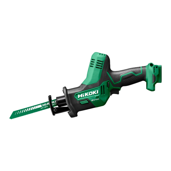
PRODUCT NAME
10.8 V Cordless Reciprocating Saw
CR 12DA
Model
CONTENTS
REPAIR GUIDE ----------------------------------------------------------------------------------------------------------------- 1
1. Precautions on disassembly and reassembly ----------------------------------------------------------- 1
• Disassembly -------------------------------------------------------------------------------------------------- 1
• Reassembly -------------------------------------------------------------------------------------------------- 3
• Tightening torque ------------------------------------------------------------------------------------------- 6
• Checking after reassembly ------------------------------------------------------------------------------- 6
• No-load current value -------------------------------------------------------------------------------------- 6
• Connecting diagram ---------------------------------------------------------------------------------------- 6
CONFIDENTIAL
Overseas Sales Management Dept.
Jul. 2020
C
Page
Advertisement

Related Manuals for Hitachi CR 12DA


Summary of Contents for Hitachi CR 12DA
-
Page 1: Table Of Contents
CONFIDENTIAL Jul. 2020 PRODUCT NAME 10.8 V Cordless Reciprocating Saw CR 12DA Model CONTENTS Page REPAIR GUIDE ----------------------------------------------------------------------------------------------------------------- 1 1. Precautions on disassembly and reassembly ----------------------------------------------------------- 1 • Disassembly -------------------------------------------------------------------------------------------------- 1 • Reassembly -------------------------------------------------------------------------------------------------- 3 • Tightening torque ------------------------------------------------------------------------------------------- 6 •... -
Page 2: Repair Guide
1. Precautions on disassembly and reassembly [Bold] numbers in the description below correspond to the item numbers in the parts list and exploded assembly diagram for the Model CR 12DA. Disassembly First, be sure to remove the saw blade from the main body to prevent damage to the cutting edges of the saw blade and avoid personal injury due to the saw blade. - Page 3 Fig. 3 • For Europe and UK Housing (B) Motor [10] [14] Housing (A) 3. Disassembly of the power supply unit (1) To disconnect the red and black internal wires of the motor in the Gear Box [1] from the DC-Speed Control Switch [10], use a soldering iron to unsolder them.
-
Page 4: Reassembly
Reassembly Perform reassembly by reversing the disassembly procedure, but note the following. 1. Reassembly of the power supply unit and its vicinity NOTE: Perform wiring correctly according to Figs. 6 and 9 being careful of the internal wiring and the connecting directions. (1) Connect each internal wire to the Battery Terminal [12] securely until the faston terminal clicks into place. - Page 5 Fig. 6 • Reassembly of the power supply unit and its vicinity 40°±10° Solder. Motor “-” terminal Internal wire (black) Internal wire (red) Red marking “+” terminal Internal wire (black) 10°±10° Internal wire (red) LED light [10]...
- Page 6 2. Reassembly of housing (A).(B) set (1) Mount the Locking Knob [5] to housing (A). (2) Put the Gear Box [1], Pushing Button (A) [7], and DC-Speed Control Switch [10] together and mount it to housing (A). NOTE: • Fit the internal wire of the LED light in the internal wire guide grooves in housing (A). •...
-
Page 7: Tightening Torque
Tightening torque • Tapping Screw (W/Flange) D3 x 16 (Black) [4] ························· 1.3±0.3 N•m {13±3 kgf•cm} Checking after reassembly Check the following after reassembly. (1) Check that the operation of the DC-Speed Control Switch [10] and Pushing Button (A) [7] is smooth and normal. - Page 8 M O D E L CR12DA Rev.1...
- Page 9 ITEM CODE DESCRIPTION REMARKS USED 376375 GEAR BOX 376553 INTERNAL WIRE (BLACK) L110 FOR CHN, UAE, THA, SIN, MAL, IND NAME PLATE 313687 TAPPING SCREW (W/FLANGE) D3 X 16 (BLACK) 376377 LOCKING KNOB 376552 INTERNAL WIRE (RED) L105 FOR CHN, UAE, THA, SIN, MAL, IND 329548 PUSHING BUTTON (A) 375921 SUPPORT (D) FOR EUROPE, GBR...