Table of Contents
Advertisement
Quick Links
All manuals and user guides at all-guides.com
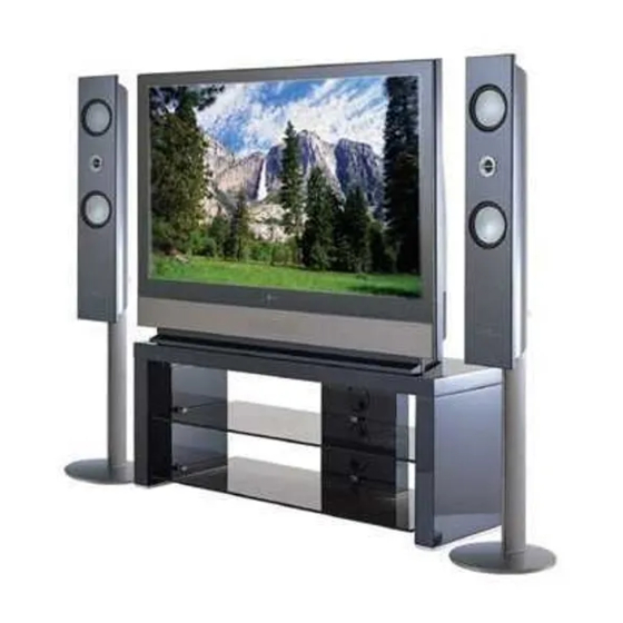
LCD Projection TV
SERVICE MANUAL
CHASSIS : MB-03CA
MODEL : RT-48SZ40RB
CAUTION
BEFORE SERVICING THE CHASSIS,
READ THE SAFETY PRECAUTIONS IN THIS MANUAL.
DOLBY
DOLBY
VIRTUAL
VIR
TUAL
e-mail:http://www.LGEservice.com/techsup.html
TV/AV
MENU
OK
VOL
PR
website:http://biz.LGservice.com
Advertisement
Table of Contents

Related Manuals for LG RT-48SZ40RB


Summary of Contents for LG RT-48SZ40RB
- Page 1 All manuals and user guides at all-guides.com website:http://biz.LGservice.com e-mail:http://www.LGEservice.com/techsup.html LCD Projection TV SERVICE MANUAL CHASSIS : MB-03CA MODEL : RT-48SZ40RB CAUTION BEFORE SERVICING THE CHASSIS, READ THE SAFETY PRECAUTIONS IN THIS MANUAL. DOLBY DOLBY VIRTUAL TUAL TV/AV MENU...
-
Page 2: Table Of Contents
All manuals and user guides at all-guides.com CONTENTS CONTENTS ........................2 SAFETY PRECAUTIONS ....................3 SERVICING PRECAUTIONS ..................4 CONTROL DESCRIPTIONS ....................6 SPECIFICATIONS ......................10 ADJUSTMENT INSTRUCTIONS ..................14 BLOCK DIAGRAM......................19 PRINTED CIRCIUT BOARD ...................23 EXPLODED VIEW ......................34 EXPLODED VIEW PARTS LIST ..................35 REPLACEMENT PARTS LIST ..................36 SVC. -
Page 3: Safety Precautions
All manuals and user guides at all-guides.com SAFETY PRECAUTIONS IMPORT ANT SAFETY NOTICE Many electrical and mechanical parts in this chassis have special safety-related characteristics. These parts are identified by the Schematic Diagram and Replacement Parts List. It is essential that these special safety parts should be replaced with the same components as recommended in this manual to prevent X-RADIATION, Shock, Fire, or other Hazards. -
Page 4: Servicing Precautions
All manuals and user guides at all-guides.com SERVICING PRECAUTIONS CAUTION: Before servicing receivers covered by this service transistors and semicounductor "chip" components. The manual and its supplements and addenda, read and follow the following techniques should be used to help reduce the SAFETY PRECAUTIONS on page 3 of this publication. - Page 5 All manuals and user guides at all-guides.com c. Qulckly move the soldering iron tip to the junction of the Fuse and Conventional Resistor component lead and the printed circuit foil, and hold it Removal/Replacement there only until the solder flows onto and around both the 1.
-
Page 6: Control Descriptions
Before you use the remote control handset, please install the bat- CABLE teries. See the next page. AUDIO Displays the selected device 2. MODE MODE selects a LG TV, VCR or DVD function. 3. TV/AV selects the remote operating mode. switches the set on from standby. 4. MULTIMEDIA selects modes. - Page 7 All manuals and user guides at all-guides.com 14. POWER switches the set on from standby or off to standby. 15. MUTE switches the sound on or off. CABLE 16. ARC (Aspect Ratio Control) AUDIO changes the picture format. MODE Q.VIEW returns to the previously viewed programme.
- Page 8 All manuals and user guides at all-guides.com Front panel Lamp indicator, operation indicator, and temperature indicator, located below the front panel con- trols reveal the operating status of the LCD projection TV. DOLBY DOLBY VIRTUAL TUAL TV/AV MENU DOLBY DOLBY VIRTUAL TUAL TV/AV...
- Page 9 All manuals and user guides at all-guides.com Rear panel S-VIDEO AV 3 INPUT INPUT SOCKET S-VIDEO VIDEO AV3 INPUT SOCKET (L)/ AUDIO MONO AV 3 INPUT S-VIDEO VIDEO (L)/ AUDIO MONO ANT IN L ANT IN 75‰ 75‰ SIDE A/V PC/DTV INPUT COMPONENT INPUT 1...
-
Page 10: Specifications
SPECIFICATIONS NOTE : Specifications and others are subject to change without notice for improvement. Scope This specification can be applied to the LCD Projection(RT-48SZ40RB) Test and Inspection Method 1) performance:Follow the Standard of LG TV test 2) Standards of Etc requirement... - Page 11 All manuals and user guides at all-guides.com Feature and Function Specification Remark Item Unit REMOCON LG Code RGB Input Separate D-Sub 15 Pin RGB Audio (L, R) Input Component Audio (R, L) Input Y, P Component Input AV Input Bottom...
- Page 12 All manuals and user guides at all-guides.com Specification Remark Item Unit DC Voltage, Digital, 5V 4.875 5.125 DC Voltage, Turning voltage DC Voltage, LCD Driver, 5V DC Voltage, LCD Driver, 17.5V 17.5 DC Voltage 3.3, SUB MICOM 3.15 3.45 DC Voltage 2.5V, SUB MICOM 2.438 2.600 DC Voltage, FAN...
- Page 13 All manuals and user guides at all-guides.com Option Specification Remark Item Unit 0 : Standard Volume Curve 1 : Non-Standard (Southeast Asia,Central America) 0 : Support FLOP Text Top 1 : Support All (FLOP + TOP) I_II SVC 0 : Do not save DUAL When converting Channel 1 : Save DUAL when Converting Channel 0 : OSRAM Lamp_Type...
-
Page 14: Adjustment Instructions
All manuals and user guides at all-guides.com ADJUSTMENT INSTRUCTIONS 1. Application Object 4. LCD adjustment This instruction is for the application to the LCD Projection 4-1. NRS adjustment [When the LCD panel load data on regular pixel using high 2. Notes speed charge/ discharge with sample &... - Page 15 All manuals and user guides at all-guides.com Optical measuring equipment Adjustment Connector for RS-232C Adjustment Cable PC Pattern Generator <Fig 2.TV set status Adjustment> (4) Adjustment Sequence 1) Turn on the adjustment Jig 2) Select RGB_PC by pressing input Select Key on Remote control.
- Page 16 All manuals and user guides at all-guides.com Follow a measurement machine manual to set CA-100and CA-110 measurement machine.] 2) pattern Generator : 1EA -> 16 step Gray Pattern, 64 step Gray Pattern 3) SET Fixation Stand : 1EA 4) Remote control : 1EA 5) Circuit thing Jig for adjustment (Except Drive Board Assy of adjustment model) --- Programmed Digital Board so that the VDP Test Pattern...
- Page 17 All manuals and user guides at all-guides.com V coefficient = 1/(number of pixel intervals between setting in the vertical 10. White Uniformity Adjustment direction) (1) Required Test Equipments Vcoeff = 1/((720/12)-1) = 0.016949152 1) Uniformity measuring equipment : Equipment which can hex (0.016949152 x 2 ) = 0 x 0456, Vcoeff (hex) = 0 x 0456 + 1 = 0 x 0457 measure chromaticity in the whole screen...
- Page 18 All manuals and user guides at all-guides.com in G MID1. Adjust screen coordinates data to adjust the color uniformity of max point. --- Change according to GMID1 and GMAX value. (use it while adjusting 4 coefficient) At this time, make sure that deviation is +5~-5% and 23.
-
Page 19: Block Diagram
All manuals and user guides at all-guides.com BLOCK DIAGRAM 1. Video Input Path - 19 -... - Page 20 All manuals and user guides at all-guides.com 2. Syns I/O Path - 20 -...
- Page 21 All manuals and user guides at all-guides.com 3. Audio Input Path - 21 -...
- Page 22 All manuals and user guides at all-guides.com 4. Control Signal Connection Diagram- IIC - 22 -...
-
Page 23: Printed Circiut Board
All manuals and user guides at all-guides.com PRINTED CIRCUIT BOARD MAIN (TOP) - 23 -... - Page 24 All manuals and user guides at all-guides.com MAIN (BOTTOM) - 24 -...
- Page 25 All manuals and user guides at all-guides.com DIGITAL(TOP) DIGITAL(BOTTOM) - 25 -...
- Page 26 All manuals and user guides at all-guides.com COMPONENT(TOP) COMPONENT(BOTTOM)) - 26 -...
- Page 27 All manuals and user guides at all-guides.com TUNER - 27 -...
- Page 28 All manuals and user guides at all-guides.com TUNER(BOTTOM) - 28 -...
- Page 29 All manuals and user guides at all-guides.com SMPS AC INPUT - 29 -...
- Page 30 All manuals and user guides at all-guides.com DRIVER(TOP) CONTROL(TOP) - 30 -...
- Page 31 All manuals and user guides at all-guides.com DRIVER(BOTTOM) CONTROL(BOTTOM) - 31 -...
- Page 32 All manuals and user guides at all-guides.com SIDE A/V POWER S/W PRE-AMP BALLAST CASE S/W SPEAKER - 32 -...
- Page 33 All manuals and user guides at all-guides.com MEMO - 33 -...
-
Page 34: Exploded View
All manuals and user guides at all-guides.com EXPLODED VIEW - 34 -... -
Page 35: Exploded View Parts List
SUPPORTER, NON AL LAMP COVER RN-48SZ40H 3680V00067A LENS, RICOH OPTICAL ENGINE RN-48SZ40 . 5900V11001D FAN,DC, B1232S12B2-LG DONGYANG 120*120*30 12V 950+-10 RPM 8-14V 300MM 5900V09005A FAN,DC G9225S12B2-RG DONGYANG 92*92*25 12V/140MA 1650+-10 RPM 8-14V 600MM 4810V00717A BRACKET, SUPPORTER RN-48SZ40 NB03JA ABS, AF-303S FAN... -
Page 36: Replacement Parts List
LA7222 (1280 AUDIO) 0TR387500AA CHIP 2SC3875S(ALY) KEC 0ISO206900A IC208 CXA2069Q QFP64 BK I2C BUS AV S/W 0TR387500AA CHIP 2SC3875S(ALY) KEC IC301 0ICTMLG003C LGDT1502M LG IC 304P QFP 0TR387500AA CHIP 2SC3875S(ALY) KEC IC302 0ITI740000Q SN74LVC00AD 14SOP 0TR387500AA Q101 CHIP 2SC3875S(ALY) KEC 0ITI740000Q... - Page 37 All manuals and user guides at all-guides.com LOCA. NO PART NO DESCRIPTION LOCA. NO PART NO DESCRIPTION Q107 0TR387500AA CHIP 2SC3875S(ALY) KEC Q207 0TR150400BA CHIP 2SA1504S(ASY) KEC 0TR387500AA CHIP 2SC3875S(ALY) KEC 0TR150400BA CHIP 2SA1504S(ASY) KEC Q108 Q208 CHIP 2SC3875S(ALY) KEC Q108 0TR387500AA Q209...
- Page 38 All manuals and user guides at all-guides.com For Capacitor & Resistors, CC, CX, CK, CN : Ceramic RD : Carbon Film the charactors at 2nd and 3rd CQ : Polyestor RS : Metal Oxide Film digit in the P/No. means as CE : Electrolytic RN : Metal Film follows;...
- Page 39 All manuals and user guides at all-guides.com For Capacitor & Resistors, CC, CX, CK, CN : Ceramic RD : Carbon Film the charactors at 2nd and 3rd CQ : Polyestor RS : Metal Oxide Film digit in the P/No. means as CE : Electrolytic RN : Metal Film follows;...
- Page 40 All manuals and user guides at all-guides.com For Capacitor & Resistors, CC, CX, CK, CN : Ceramic RD : Carbon Film the charactors at 2nd and 3rd CQ : Polyestor RS : Metal Oxide Film digit in the P/No. means as CE : Electrolytic RN : Metal Film follows;...
- Page 41 All manuals and user guides at all-guides.com For Capacitor & Resistors, CC, CX, CK, CN : Ceramic RD : Carbon Film the charactors at 2nd and 3rd CQ : Polyestor RS : Metal Oxide Film digit in the P/No. means as CE : Electrolytic RN : Metal Film follows;...
- Page 42 SW07 140-315A TACT SKHV17910B LG C&D NON 12V 330K OHM 1/4 W 1.00% TA52 R805 0RN3303G409 140-313A TACT 2LEAD 100G(TA) LG C&D NON 5V 0.001A R805B 0RD3300F609 330 OHM 1/6 W 5.00% TA52 SW801 140-289A POWER SDDF3PASP013 LG C&D UL/C...
- Page 43 All manuals and user guides at all-guides.com LOCA. NO PART NO DESCRIPTION LOCA. NO PART NO DESCRIPTION AT1304 0LCCE00018A HB-4M3216-301JT R/TP 100MHZ 300OHM T402 6200QJ3001A FILTER,EMI REEL/TAPING BMS400 25V 200MA 0LCCE00018A HB-4M3216-301JT R/TP 100MHZ 300OHM 6200VJT006A AT1305 T402 STC222D NIIGATA 50VOLT 4A 2200PF HB-4M3216-301JT R/TP 100MHZ 300OHM AT1306 0LCCE00018A...
- Page 44 36510-0032 MOLEX 48PIN PITCH2.54MM P403 6612BBBHN6A 440062-1 AMP DVI INTERACED RIGHT ANGLE ACCESSORIES 3828VA0447T MANUAL,OWNERS MB03CA AP 116T TX 395A 6710V00116T REMOTE CONTROLLER,MB03CA RT-48SZ40RB 172-050V CABLE,COAXIAL(UL1365,2.5C-2V 100M/M) MISCELLANEOUS 0FS5001B51D F800 FUSE,SLOW BLOW 5000MA 250 V 5.2X20 6620VF3201A SOCKET(CIRC),IC 822473-3 AMP 32PIN 2.54MM...
- Page 45 All manuals and user guides at all-guides.com ice.com up.html...
- Page 46 All manuals and user guides at all-guides.com...
- Page 47 All manuals and user guides at all-guides.com...
- Page 48 All manuals and user guides at all-guides.com...
- Page 49 All manuals and user guides at all-guides.com...
- Page 50 All manuals and user guides at all-guides.com PRINTED CIRCUIT BOARD MAIN(TOP) MAIN(BOTTOM) DIGITAL(TOP) DIGITAL(BOTTOM) COMPONENT(TOP) COMPONENT(BOTTOM) SMPS DRIVER(TOP) TUNER(TOP) TUNER(BOTTOM) DRIVER(BOTTOM) AC-INPUT SIDE A/V...
- Page 51 All manuals and user guides at all-guides.com RT-44/52SZ50LP RT-48SZ50LP CONTROL(TOP) INDEX(TOP) CONTROL(BOTTOM) INDEX(BOTTOM) LED(TOP) LED(TOP) LED(BOTTOM) LED(BOTTOM) CASE SW BALLAST SIDE AV BALLAST SIDE AV POWER S/W PRE-AMP CASE SW PRE-AMP POWER S/W...