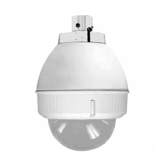
Sony UNI-OFL7C2 Series Installation And Operation Instructions Manual
Outdoor and indoor recessed dome housings
Hide thumbs
Also See for UNI-OFL7C2 Series:
Table of Contents
Advertisement
Quick Links
Installation and Operation Instructions for the following models:
UNI-OFL7C2 & UNI-OFL7T2 SERIES
Outdoor and Indoor Recessed Dome Housings
UNIOFL7C2
Outdoor recessed housing, clear dome, 24VAC input, heater & blower
UNIOFL7T2
Outdoor recessed housing, tinted dome, 24VAC input, heater & blower
Note: AC 24V power supply for the camera and the heater/blower is an installer/re-seller
provided item please refer to page 3 Electrical Specifications for power consumption
details.
Note: Please note that to achieve the increased depth with the aspheric design for optimal
camera lens to capsule orientation, the capsule is slightly angled around the highest
section. This creates a "line', visible to the naked eye, around the upper most section
of the capsule. This "line" serves as the geometric center line used to insure proper
camera placement. It is not typically seen by the camera. However, Sony RZ series PTZ
cameras are able to tilt up above the horizon to 25°, this wide range of tilt motion at
a wide angle view may cause this line to be captured in the image.
Mounting instructions for:
SNC-RZ25, 30, 50
SNC-RX530, 550, 570
SNC-RH124
SNC-RS44, 46
SNC-EP580, 550, 520
SNC-ER580, 550, 520
81-IN6525
04272012
Advertisement
Table of Contents

Related Manuals for Sony UNI-OFL7C2 Series


Summary of Contents for Sony UNI-OFL7C2 Series
- Page 1 This “line” serves as the geometric center line used to insure proper camera placement. It is not typically seen by the camera. However, Sony RZ series PTZ cameras are able to tilt up above the horizon to 25°, this wide range of tilt motion at a wide angle view may cause this line to be captured in the image.
-
Page 2: Important Safeguards
à presença de instruções importantes na literatura que acompanha o dispositivo. If technical support or service is needed, contact Sony at the following number: Questo simbolo del punto del exclamaton è inteso per avvertire l’utente alla presenza delle istruzioni importanti nella letteratura che accompagna l’apparecchio. -
Page 3: Contents Of Box
Contents of Box Contents of Box Details (1) Spacer Packet 2” ½” 1” 200mm 25mm 50mm (1) Spacer Packet (4) M3 x 6mm Machine Screw (4) M3 lock washers (1) 1/4 x 20 Bolt (1) 1/4 flat washer (1) 1/4 lock washer (3) 8 x 32 x 3/8"... -
Page 4: Electrical Specifications
Electrical Specifications UNI-OFL7C2 UNI-OFL7T2 Power 24VAC, Class 2 Only (OUTDOOR ONLY): UNI-OFL7C2 & UNI-OFL7T2 26 Watts at 24 VAC (Heater and Blower) Approximately 25 Watts at 24 VAC (Camera)* *Refer to applicable camera specs for precise consumption Tools Required: .100" Flat Head Screwdriver Phillips Head Screwdriver (ONLY AL AIRE LIBRE): UNI-ONL7C2 y UNI-ONL7T2... - Page 5 Camera Installation: SNC-RZ25 SNCRZ25 MOUNTING HOLES Remove the quick release plate from the Mount the camera to the plate using the housing. appropriate pattern and hardware. • Monte la cámara fotográfica a la placa usando el • Quite la placa rápida del lanzamiento de la cubierta. patrón apropiado.
- Page 6 Camera Installation: SNC-RX530 / 550 / 570 SNCRX550 SNC RX550 MOUNTING HOLES Remove the quick release plate from the Mount the camera to the plate using the housing. appropriate pattern. • Monte la cámara fotográfica a la placa usando el •...
- Page 7 Camera Installation: SNC-RH124 / RS44 / RS46 SNC-RH124 SNC-RH124 SNC-RS44 SNC-RS44 SNC-RS46 SNC-RS46 Remove existing bracket to mount SNC-RH124 Leave four 1/2” spacers as shown. or the SNC-RS series cameras. • Retire el soporte existentes para organizar SNC-RH124 o la •...
- Page 8 • Conecte el control y accione los alambres a la base de la (de 25m m) en la cubierta. cámara, (véase las instrucciones de la cámara de Sony). • Attachez le plat de plafond de SNC RH124 » aux entretoises 1 •...
- Page 9 Camera Installation: SNC-EP/ER SERIES (EP580, 550, 520 and ER580, 550, 520) 1½” spacers ½” spacers NOTE: Mounting holes for cameras SNC-EP/ER Add (4) 1” and (4) ½“ spacers to the base bracket Series (These holes include threaded inserts) as shown. NOTE: ½“ spacers already in place. •...
- Page 10 Camera Installation: SNC-EP/ER SERIES (EP580, 550, 520 and ER580, 550, 520) Cont. Twist the camera clockwise to secure it to Attach the camera to the camera plate. the plate. • Ate la cámara a la placa de la cámara. • Tuerza la cámara a la derecha para asegurarla a la placa. •...
- Page 11 A box cutter or jigsaw can be used for Using the provided template, mark the cutting the circle. ceiling tile for the cutout. • Un cortador o un rompecabezas de la caja se • Con la plantilla proporcionada, cortar el azulejo del puede utilizar para cortar el círculo.
- Page 12 Add the safety wire to the flex conduit or Connect the flex conduit to the housing. continue to the next step. • Agregue el alambre de seguridad al conducto de la • Conecte el conducto de la flexión con la flexión o continúe al paso siguiente.
- Page 13 24Vdc Power and Control Inputs (Outside of Housing) RJ45 Camera Power (+ 24 VDC) Refer to camera 24VAC Camera Power (- 24 VDC) POWER Orange product manuals RJ45 Camera regarding power Max 40 Watts Accessory Power (+ 24 VDC) Yellow Camera Orange consumption.
- Page 14 The beam angle may be adjusted on the bottom of the unit. I nstall the camera in the housing and complete The beam angle may be adjusted on the Hook the lanyard from the dome to the wiring applications. See camera specifications. bottom of the unit.
-
Page 16: Materials Needed
How - to Clean a Dome Bubble To effectively clean your video surveillance dome bubble (acrylic or polycarbonate) from debris, follow these simple step-by-step instructions. Materials Needed • Clean, dry, pressurized air • Water • High quality soft paper towel •... - Page 17 This “line” serves as the geometric center line used to insure proper camera placement. It is not typically seen by the camera. However, Sony RZ series PTZ cameras are able to tilt up above the horizon to 25°, this wide range of tilt motion at a wide angle view may cause this line to be captured in the image.
- Page 18 Available Mounting Accessories UNI-WMB1 UNI-PBU1 UNI-CMA1 UNI-RMB1 UNI-PMA1 Aluminum Gooseneck Aluminum Existing Aluminum Corner Power Block Unit Parapet Mount Wall Mount Pole Mount Adaptor Mount Adaptor UNI-WMB1 UNI-PMA1 Wall Mount Pole Mount Mounting Accessories Needed: Mounting Accessories Needed: • UNI-WMB1 - Gooseneck UNI-WMB1 - Gooseneck Wall Mount Wall Mount Outdoor Pendant Housing...