Table of Contents
Advertisement
Advertisement
Table of Contents

Related Manuals for Acer Aspire X1470


Summary of Contents for Acer Aspire X1470
- Page 1 Aspire AX1470 Desktop Computer Service Guide PRINTED IN TAIWAN...
-
Page 2: Revision History
Revision History Refer to the table below for changes made on this version of the Aspire AX1470 Desktop Computer Service Guide. Date Chapter Updates Aspire AX1470 Service Guide... - Page 3 Copyright Copyright © 2011 by Acer Incorporated. All rights reserved. No part of this publication may be reproduced, transmitted, transcribed, stored in a retrieval system, or translated into any language or computer language, in any form or by any means, electronic, mechanical, magnetic, optical, chemical, manual or otherwise, without the prior written permission of Acer Incorporated.
- Page 4 Conventions The following conventions are used in this service guide. Denotes actual messages that appear on screen. SCREEN MESSAGES NOTE Gives additional information related to the current topic. WARNING Alerts you to any physical risk or system damage that might result from doing or not doing specific actions.
-
Page 5: Fru Information
FRU list of this printed service guide. You MUST use the list provided by your regional Acer office to order FRU parts for repair and service of customer machines. Aspire AX1470 Service Guide... - Page 6 Aspire AX1470 Service Guide...
-
Page 7: Table Of Contents
Features and Specifications... 1 System Features ............1 Audio . - Page 8 Table of Contents BIOS Update ............78 Updating the BIOS in DOS Mode .
-
Page 9: Features And Specifications
Features and Specifications This chapter lists the features and specifications of the Aspire AX1470 computer. NOTE: The items listed in this section are for reference only. The exact configuration of your PC depends on the model purchased. Refer to the FRU list chapter on page 95 for a detailed list of models supported by each hardware component. -
Page 10: Audio
Component Power supply Antivirus software System BIOS Power management Audio Item Audio codec Audio jacks I/O Ports and LED Indicators Component I/O ports LED display and buttons Description 220 W power supply unit (non-PFC, non-power factor correction) 220 W power supply unit (PFC) Norton Internet Security •... -
Page 11: Physical Specifications
Physical Specifications Aspect Chassis dimension (W × D × H) System weight Mainboard form factor Mainboard dimensions (W × H) Environmental Requirements Aspect Operating temperature Operating humidity Aspire AX1470 Service Guide Description 100 mm (W) X 367.8 mm (D) x 268.5 mm (H) 5.808 kg. -
Page 12: System Tour
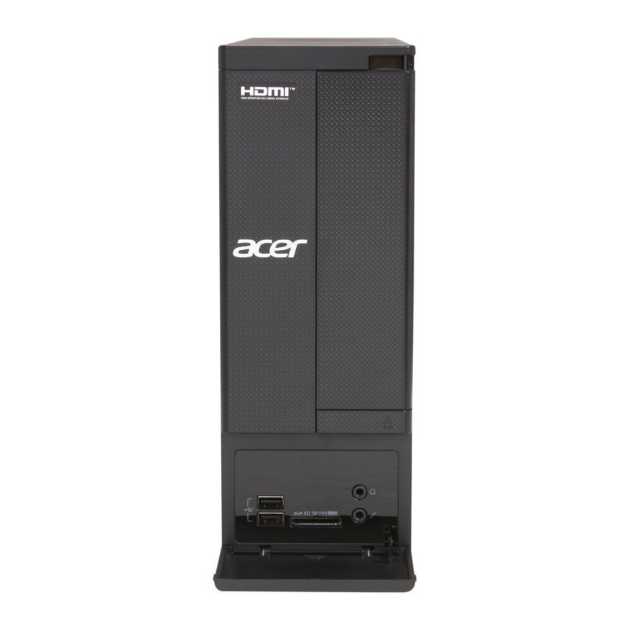
The pictures and tables in this section illustrate the physical outlook of the computer. Front View Component Power button/indicator Optical drive cover Optical drive eject button Headphone jack Microphone-in jack Multi-in-1card reader (optional) USB 2.0 ports Acer logo Aspire AX1470 Service Guide... -
Page 13: Rear View
Rear View Component Expansion slots Line-in jack Line-out jack Microphone jack USB 2.0 ports External monitor port HDMI port PS/2 keyboard connector PS/2 mouse connector Fan aperture Voltage selector switch Power connector Kensington lock Key lock LAN connector USB 3.0 ports Aspire AX1470 Service Guide... - Page 14 Aspire AX1470 Service Guide...
-
Page 15: System Utilities
System Utilities CMOS Setup Utility CMOS setup is a hardware configuration program built into the system ROM, called the complementary metal- oxide semiconductor (CMOS) Setup Utility. Since most systems are already properly configured and optimized, there is no need to run this utility. You will need to run this utility under the following conditions. When changing the system configuration settings •... -
Page 16: Entering Cmos Setup
Entering CMOS Setup Turn on the computer and the monitor. If the computer is already turned on, close all open applications, then restart the computer. During POST, press Delete. If you fail to press Delete before POST is completed, you will need to restart the computer. The Setup Main menu will be displayed showing the Setup’s menu bar. -
Page 17: Setup Utility Menus
Setup Utility Menus The Setup Main menu includes the following main setup categories. Main • Advanced • Power • Security • Boot Options • Exit • In the descriptive table following each of the menu screenshots, settings in boldface are the default and suggested settings. - Page 18 Main The Main menu displays basic information about the system. Parameter Description System BIOS Version Version number of the BIOS setup utility. Build Date Date when the BIOS setup utility was built. Processor Type of CPU installed on the system. Core Frequency Core speed of the CPU installed on the system.
- Page 19 Advanced Parameter Miscellaneous Advanced Chipset Configuration Integrated Peripherals PC Health Status Aspire AX1470 Service Guide Description Press Enter to access the Miscellaneous submenu Press Enter to access the Advanced Chipset Configuration submenu Press Enter to access the Integrated Peripherals submenu Press Enter to access the PC Health Status submenu...
- Page 20 Miscellaneous Parameter Description AHCI Port0/1/2/ Displays the status of auto detection of the AHCI device. Clock to All DIMM/PCI/ Enables or disables the system to detect the DIMM/PCI/PCIE clock PCIE automatically during bootup. Spread Spectrum Enables or disables the reduction of the mainboard’s EMI. Note: Remember to disable the Spread Spectrum feature if you are overclocking.
- Page 21 Advanced Chipset Configuration Parameter Description AMD Turbo Core Enables or disables AMD Turbo Core Technology. AMD Cool’n’Quiet When enabled, the Cool’n’Quiet feature reduces the heat and noise emitted by the CPU. AMD-V Enables or disables the Virtualization Technology (VT) availability. If enabled, a virtual machine manager (VMM) can utilize the additional hardware virtualization capabilities provided by this technology.
- Page 22 Integrated Peripherals Parameter Description Onboard SATA Enables or disables the onboard SATA controller. Controller Onboard SATA Mode Select an operating mode for the onboard SATA. Onboard USB Controller Enables or disables support for legacy USB devices Legacy USB Support Enables or disables support for legacy USB devices. USB Storage Emulation Select emulation type for a USB mass storage device.
- Page 23 PC Health Status Parameter Description Smart Fan Enables or disables the smart system fan control function. Aspire AX1470 Service Guide Option Enabled Disabled...
- Page 24 Power Parameter Description ACPI Suspend Mode Select an ACPI state. Deep Power Off Mode Enables or disables the deep power off mode. Power On by RTC Alarm Enables or disables real time clock (RTC) to generate a wake event. Power On by PCIE Enables or disables to wake up the system from a power saving Devices mode through an event on a PCI Express device.
- Page 25 Security Parameter Description Supervisor Password Indicates the status of the supervisor password. User Password Indicates the status of the user password. Change Supervisor Supervisor password prevents unauthorized access to the BIOS Setup Utility. Password Press Enter to change the Supervisor password. Change User Password Press Enter to change the User password.
-
Page 26: Boot Options
Boot Options Parameter Description 1st/2nd/3rd/4th/5th Boot Specifies the boot order from the available devices. Device EFI Device Priority Press Enter to access the EFI Device Priority submenu and specify the boot device priority sequence from available EFI devices. Hard Disk Drive Priority Press Enter to access the Hard Disk Drive Priority submenu and specify the boot device priority sequence from available hard drives. - Page 27 Exit Parameter Description Save & Exit Setup When you have completed the system configuration changes, select this option to leave the BIOS Setup Utility and reboot the computer, so the new system configuration parameters can take effect. Select Save & Exit Setup from the Exit menu and press Enter.
- Page 28 AX1470 Service Guide...
-
Page 29: System Disassembly
System Disassembly This chapter provides step-by-step instructions on how to disassemble the computer for maintenance and troubleshooting purposes. Disassembly Tools In performing the disassembly process, you will need the following tools: • Wrist-grounding strap and conductive mat for preventing electrostatic discharge •... -
Page 30: Disassembly Procedures
Disassembly Procedures Removing the Side Panel Remove the two screws located on the rear edge of the side panel. Slide the panel back about 2.5 cm (1.0 in) to release it from the chassis notches, then detach the panel from the chassis. Put the side panel aside for reinstallation later. -
Page 31: Removing The Front Bezel
Removing the Front Bezel Release the front bezel retention tabs from the chassis interior. Pull the front bezel away from the chassis. NOTE: The power switch and LED cable from the front bezel is still connected to its connector on the mainboard. -
Page 32: Removing The Heat Sink Fan Assembly
Removing the Heat Sink Fan Assembly WARNING: The heat sink becomes very hot when the system is on. NEVER touch the heat sink with any metal or with your hands. Use a phillips screwdriver to loosen the four screws on the heat sink, in the order as shown below. Lift the heat sink fan assembly away from the mainboard. -
Page 33: Removing The Processor
Removing the Processor IMPORTANT:Before removing a processor from the mainboard, make sure to create a backup file of all important data. WARNING: The processor becomes very hot when the system is on. Allow it to cool off first before handling. Release the load lever (1). -
Page 34: Removing The Hdd-Odd Bracket
Removing the HDD-ODD Bracket Remove the two screws that secure the HDD-ODD bracket to the chassis. Lift the bracket up and turn it over. Aspire AX1470 Service Guide... -
Page 35: Removing The Optical Drive And The Hard Disk Drive
Removing the Optical Drive and the Hard Disk Drive Disconnect the power (1) and SATA (2) cables from the rear of the optical drive. Disconnect the other end of the SATA cable from the mainboard. Aspire AX1470 Service Guide... - Page 36 Disconnect the SATA (1) and power (2) cables from the rear of the hard disk drive. Remove the screws that secure the optical drive to the HDD-ODD bracket. Aspire AX1470 Service Guide...
- Page 37 Pull the optical drive out of the drive bay. Remove the four screws that secure the hard disk drive to the HDD bracket. Slide the hard disk drive out of the bracket. Aspire AX1470 Service Guide...
-
Page 38: Detaching The Front Bezel
Detaching the Front Bezel Disconnect the power button/LED cable from its mainboard connector. Pull out the power button/LED cable from the chassis. Detach the front bezel. Aspire AX1470 Service Guide... -
Page 39: Removing The Optional Expansion Boards
Removing the Optional Expansion Boards Remove the screw from the expansion board bracket opposite the PCIe x16 slot. Gently pull up the expansion board (1), move it slightly to the left and remove (2) from the slot. Remove the screw from the expansion board bracket opposite the PCIe x1 slot. Gently pull up the expansion board (1), move it slightly to the left and remove (2) from the slot. -
Page 40: Removing The Memory Modules
Removing the Memory Modules Open the holding clips (1) that secure the memory modules. Gently pull the DIMM upward (2) to pull it away from the chassis. NOTE: Circuit board has been highlighted with the yellow rectangle as above image shows. Please detach the circuit board and follow local regulations for disposal. -
Page 41: Removing The Power Supply Unit
Removing the Power Supply Unit Disconnect the 4-pin and the 24-pin ATX power supply cables from its mainboard connector. Squeeze on the retaining latch (1) attached to the cable end of the connector. Grasp the cable end of the connector and pull it straight up (2). Remove the screw that secures the power supply to the chassis. - Page 42 Remove the two screws that secure the power supply to the rear panel. Push the power supply module (1) toward the front. Tilt the power supply module slightly to the right (2) and lift it out of the chassis (3). Aspire AX1470 Service Guide...
-
Page 43: Removing The Front I/O And Optional Card Reader Assemblies
Removing the Front I/O and Optional Card Reader Assemblies Disconnect the front I/O, card reader and SATA cables from their mainboard connectors. Open the plastic clip (1) and release the cables from the metal clip (2) in the direction indicated. Aspire AX1470 Service Guide... - Page 44 Detach the cables from the front I/O and optional card reader board. Remove the cables. Remove the screw that secures the bracket to the chassis. Pull the bracket out from the chassis. Aspire AX1470 Service Guide...
- Page 45 Remove the two screws that secure the front I/O and optional card reader assembly to the bracket. Remove the front I/O and optional card reader assembly from the bracket. Aspire AX1470 Service Guide...
-
Page 46: Removing The Mainboard
Removing the Mainboard Remove the six screws that secure the mainboard to the chassis. NOTE: Circuit board has been highlighted with the yellow rectangle as above image shows. Please detach the circuit board and follow local regulations for disposal. Lift the board from the chassis. - Page 47 Remove the RTC battery. NOTE: The RTC battery has been highlighted with the yellow circle as above image shows. Please detach the RTC battery and follow local regulations for disposal. Aspire AX1470 Service Guide...
-
Page 48: Reassembly Procedures
Reassembly Procedures Reinstalling the Mainboard Slide the mainboard into the chassis, with the I/O ports of the mainboard extruding from their port holes, then lower the mainboard in place. Make sure the screw holes on the main board are aligned with those on the chassis. Secure the mainboard with six screws. - Page 49 Install the RTC battery into the battery holder on the mainboard.. Aspire AX1470 Service Guide...
-
Page 50: Reinstalling The Front I/O And Optional Card Reader Assembly
Reinstalling the Front I/O and Optional Card Reader Assembly Insert the front I/O and optional card reader assembly into the bracket. Secure the front I/O and optional card reader assembly to the bracket using two screws. Install the bracket into the chassis. Aspire AX1470 Service Guide... - Page 51 Secure the bracket to the chassis with one screw. Connect the cables to the front I/O and optional card reader assembly. Insert all cables into the metal clip (1) and plastic clip (2). Press to close the plastic clip (3). Make sure that all cables are arranged properly and lay as close as possible to the chassis to facilitate the re- installation of the HDD-ODD bracket later.
- Page 52 Connect the front I/O, card reader and SATA cables to their mainboard connectors. Aspire AX1470 Service Guide...
-
Page 53: Reinstalling The Power Supply Unit
Reinstalling the Power Supply Unit Slide the power supply module into the chassis (1) and tilt to the left. Push the power supply module toward the rear (2), until the power connector extrudes from the rear panel. Aspire AX1470 Service Guide... - Page 54 Secure the power supply to the rear panel using two screws. Secure the power supply to the chassis using one screw. Connect the ATX power supply cables to its mainboard connector. Aspire AX1470 Service Guide...
-
Page 55: Installing The Memory Modules
Installing the Memory Modules Insert the memory module into the DIMM1 slot (1) and then press it down until it clicks into place (2). If additional memory modules are available, install it in the other DIMM slots by repeating step 1. Aspire AX1470 Service Guide... -
Page 56: Installing The Optional Expansion Boards
Installing the Optional Expansion Boards Position the expansion board over the PCIe x16 slot and move it slightly to the right (1), making sure the card guide is aligned with the slot guide on the chassis. Insert the expansion card properly into the PCIe x16 slot (2). - Page 57 Position the expansion board over the PCIe x1 slot and move it slightly to the right (1), making sure the card guide is aligned with the slot guide on the chassis. Insert the expansion card properly into the PCIe x1 slot (2). Secure the expansion board bracket opposite the PCIe x1 slot using one screw.
-
Page 58: Reinstalling The Front Bezel Power Button/Led Cable
Reinstalling the Front Bezel Power Button/LED Cable Insert the power button/LED cable through the front of the chassis. Connect the power button/LED cable to its mainboard connector. Aspire AX1470 Service Guide... -
Page 59: Reinstalling The Optical Drive And The Hard Disk Drive
Reinstalling the Optical Drive and the Hard Disk Drive Slide the hard disk drive into the drive bay. Secure the hard disk drive to the HDD-ODD bracket using four screws. Aspire AX1470 Service Guide... - Page 60 Slide the optical drive into the drive bay. Secure the optical drive to the HDD-ODD bracket using two screws. Aspire AX1470 Service Guide...
- Page 61 Connect the SATA (1) and power (2) cables to their connectors on the rear of the hard disk drive. Connect one end of the SATA cable to the SATA1 connector on the mainboard. Aspire AX1470 Service Guide...
- Page 62 Connect the power (1) and SATA (2) cables to their connectors on the rear of the optical drive. Aspire AX1470 Service Guide...
-
Page 63: Reinstalling The Hdd-Odd Bracket
Reinstalling the HDD-ODD Bracket Install the HDD-ODD bracket into the chassis. Secure the HDD-ODD bracket to the chassis using two screws. Aspire AX1470 Service Guide... -
Page 64: Reinstalling The Processor
Reinstalling the Processor WARNING:Note the arrow on the corner and make sure the processor is properly oriented over the socket. With the load lever in the fully upright position, press the processor into the socket. Push the load lever downward (1) until it locks into place at the side of the socket (2). Aspire AX1470 Service Guide... -
Page 65: Reinstalling The Heat Sink Fan Assembly
Reinstalling the Heat Sink Fan Assembly WARNING: The heat sink becomes very hot when the system is on. NEVER touch the heat sink with any metal or with your hands. Connect the fan cable to its mainboard connector. Position the heat sink fan assembly on top of the processor, making sure the screws are aligned with the screw holes on the mainboard. -
Page 66: Reinstalling The Front Bezel
Reinstalling the Front Bezel Insert the tabs on the front bezel into the notches (1) on the left side of the chassis and attach the front bezel (2) in the direction indicated. . Make sure the front bezel retention tabs are securedly fastened to the chassis interior. Aspire AX1470 Service Guide... -
Page 67: Reinstalling The Side Panel
Reinstalling the Side Panel Align the tabs on the lower edge of the side panel with the notches on the bottom side of the chassis. Align the tabs on the upper edge of the side panel with the notches on the top side of the chassis. Aspire AX1470 Service Guide... - Page 68 Push the side panel toward the front of the chassis until it is firmly closed. Secure the side panel to the rear edge of the chassis using two screws. Aspire AX1470 Service Guide...
-
Page 69: Troubleshooting
System Check Procedures IMPORTANT: The diagnostic tests described in this chapter are only intended to test Acer products. Non-Acer products, prototype cards, or modified options can give false errors and invalid system responses. -
Page 70: Checkpoints
Verify that all power and data cables are firmly and properly attached to the installed drives. Verify that all cable connections inside the system are firmly and properly attached to their appropriate mainboard connectors. Verify that all components are Acer-qualified and supported. 10. Reinstall the side panel. 11. Power on the system. -
Page 71: Boot Block Recovery Code Checkpoints
Checkpoint Description Both key sequence and OEM specific method is checked to determine if BIOS recovery is forced. Main BIOS checksum is tested. If BIOS recovery is necessary, control flows to checkpoint E0. See the “Boot Block Recovery Code Checkpoints” section for more information. -
Page 72: Post Code Checkpoints
POST Code Checkpoints The POST code checkpoints are the largest set of checkpoints during the BIOS preboot process. The following table describes the type of checkpoints that may occur during the POST portion of the BIOS. Checkpoint Description Disable NMI, Parity, video for EGA, and DMA controllers. Initialize BIOS, POST, Runtime data area. - Page 73 Checkpoint Description Mid POST initialization of chipset registers. Detect different devices (Parallel ports, serial ports, and coprocessor in CPU, ... etc.) successfully installed in the system and update the BDA, EBDA…etc. Programming the memory hole or any kind of implementation that needs an adjustment in system RAM size if needed.
-
Page 74: Post Error Indicators
DIM Code Checkpoints The Device Initialization Manager (DIM) gets control at various times during BIOS POST to initialize different system busses. The following table describes the main checkpoints where the DIM module is accessed. Checkpoint Description Initialize different buses and perform the following functions: Reset, Detect, and Disable (function 0);... - Page 75 Memory Message Description Gate20 Error The BIOS is unable to properly control the mainboard’s Gate A20 function, which controls access of memory over 1 MB. This may indicate a problem with the mainboard. Multi-Bit ECC Error This message will only occur on systems using ECC enabled memory modules. ECC memory has the ability to correct single-bit errors that may occur from faulty memory modules.
-
Page 76: Storage Device
Storage Device Message Description Primary Master Hard The IDE/ATAPI device configured as Primary Master could not be properly Disk Error initialized by the BIOS. This message is typically displayed when the BIOS is trying to detect and configure IDE/ATAPI devices in POST. Primary Slave Hard The IDE/ATAPI device configured as Primary Slave could not be properly initialized Disk Error... - Page 77 Message Description 3rd Slave Drive - The IDE/ATAPI device configured as Slave in the 3rd IDE controller failed an ATAPI Incompatible ATAPI compatibility test. This message is typically displayed when the BIOS is trying to detect and configure IDE/ATAPI devices in POST. 4th Master Drive - The IDE/ATAPI device configured as Master in the 4th IDE controller failed an ATAPI Incompatible...
-
Page 78: System Configuration
Virus-related Message Description BootSector Write!! The BIOS has detected software attempting to write to a drive’s boot sector. This is flagged as possible virus activity. This message will only be displayed if Virus Detection is enabled in AMIBIOS setup. VIRUS: Continue If the BIOS detects possible virus activity, it will prompt the user. - Page 79 CMOS Message Displayed Description CMOS Date/Time The CMOS date and/or time are invalid. This error can be resolved by readjusting Not Set the system time in AMIBIOS Setup. CMOS Battery Low CMOS battery is low. This message usually indicates that the CMOS battery needs to be replaced.
- Page 80 Index of Symptom-to-FRU Error Messages To use the information in this section to diagnose a problem: Find the error symptom in the left column. If directed to a check procedure, replace the FRU indicated in the check procedure. If no check procedure is indicated, the first Action/FRU item listed in the right column is the most likely cause.
- Page 81 Hard Disk Drive-related Symptoms Symptom/Error Hard disk drive test failed. Hard disk drive cannot format completely. Hard disk drive has write error. Hard disk drive LED fails to light, but system operates normally. NOTE: Make sure the hard disk drive is configured correctly in CMOS Setup and that cable/jumper are set correctly before diagnosing any hard disk drive problems.
- Page 82 Real-Time Clock-related Symptoms Symptom/Error Real-time clock is inaccurate. Audio-related Symptoms Symptom/Error Audio software program invoked but no sound comes from speakers. Modem-related Symptoms Symptom/Error Modem ring cannot wake up system from suspend mode. Data/fax modem software program invoked but cannot receive/send data/fax Fax/voice modem software program invoked but has no sound output.
- Page 83 Video and Monitor-related Symptoms Symptom/Error Display changing colors. Printer-related Symptoms Symptom/Error Printing failed. Printer problems. Keyboard-related Symptoms Symptom/Error Some or all keys on keyboard do not work. Power Supply-related Symptoms Symptom/Error Pressing the power button does not turn off the system. (Only unplugging the power cord from electrical outlet can turn off the system.) Pressing the power button does not turn on...
-
Page 84: Beep Codes
Follow the procedures below to isolate the failing FRU. Do not isolate non-defective FRU. Power off the computer. Visually check them for damage. If any problems are found, replace the FRU. Remove or disconnect all of the following devices: • Non-Acer devices • Printer, mouse, and other external devices • Hard disk drive •... -
Page 85: Bios Recovery
BIOS Recovery When you boot up the computer and you hear one long beep, followed by a shorter one, the system BIOS is damaged. This maybe cause by an interruption during a BIOS flash procedure (e.g. a power outage) or a corrupted BIOS code, which will cause the system to go into an unbootable state.You need to access and execute the boot block program to reboot the computer and recover the regular BIOS code. -
Page 86: Bios Update
BIOS Update Updating the BIOS in DOS Mode Press the power button to turn on the computer and boot to DOS mode. Key in 'cd dostool'. (Go to BIOS path like "A:\DOSTOOL") Key in 'flash1M.bat' or 'flash1M'. Press Enter to flash the system BIOS. Reboot the computer. -
Page 87: Updating The Bios In Windows Mode
Updating the BIOS in Windows Mode This BIOS updating procedure is for a computer running a 32- or 64-bit Windows OS. Press the power button to turn on the computer. Click Start | Command Prompt | Run as administrator. Perform the steps below if your computer is running 32-bit Windows. Key in 'cd wintool\32'. - Page 88 Press Enter to flash the system BIOS. Perform the steps below if your computer is running 64-bit Windows. Key in 'cd wintool\64'. (Go to BIOS path like "D:\WinTool\64") Key in 'flash1M.bat' or 'flash1M'. Aspire AX1470 Service Guide...
- Page 89 Press Enter to flash the system BIOS. Reboot the computer. Press Delete to run the CMOS Setup Utility. Press F9 to load the system default settings. Select Ok, then press Enter. Press F9 to save the default settings and close the Setup utility. 10.
-
Page 90: Clearing Cmos
Clearing CMOS You may need to clear the Setup configuration values (CMOS) if the configuration has been corrupted, or if incorrect settings made in the Setup Utility caused error messages to be unreadable. This procedure will clear the BIOS supervisor password as well. Use the JP1701 jumper to clear the CMOS data. -
Page 91: System Architecture
System Architecture This chapter shows the block diagram and board layout of the Aspire AX1470 computer. Block Diagram The core subsystems of the Aspire AX1470 computer are depicted in the following block diagram: Aspire AX1470 Service Guide Chapter 5... -
Page 92: Mainboard Layout
Mainboard Layout This section shows the major mainboard components. Label Description CPU socket CPUFAN1 CPU cooling fan connector DIMM1-4 DDR3 240-pin slots PWR2 Standard 24-pin power connector ITE 8758 JP1701 Clear CMOS jumper SATA1-3 Serial ATA connectors LEDH1 12-pin power cable header USBF 2-3 Front panel USB header USBF 1... -
Page 93: Jumper Setting
Jumper Setting This section explains how to set the jumper for correct configuration of the main board. Jumpers with more than one pin are numbered. When setting a jumper, ensure that the jumper caps are placed on the correct pins. The following illustration shows the location of JP1701: The following table shows the settings of the 3-pin Clear CMOS (JP1701) jumper. -
Page 94: Internal Header Pin Definition
Internal header pin definition Header Name Function CPU FAN HEADER FRONT PANEL HEADER FRONT USB HEADER FRONT USB HEADER FRONT AUDIO HEADER Definition 1: GND 2: +12V 3: SENSE 4: PWM CONTROL 1: SATALED+ 2: ACPI_LED 3: SATALED- 4: PWR_LED 5: GND 6: PWR_SW 7: RESET... -
Page 95: Connector Pin Definition
Connector pin definition Header Name Function PSKBMS CONN VGA CONN SATA CONN SATA CONN ATX_POWER CONN Aspire AX1470 Service Guide Definition 1: KBDATA 2: NC 3: GND 4: KBVCCSB 5: KBCLK 6: NC 7: MSDATA 8: NC 9: GND 10: KBVCCSB 11: MSCLK 12: NC 13: GND... - Page 96 Header Name Function ATX12V CONN Definition 1: GND 2: GND 3: +12V_4P 4: +12V_4P Aspire AX1470 Service Guide...
-
Page 97: Connecting Optional Devices
Connecting Optional Devices Refer to the following for information on connecting the main board’s optional devices: SATA1~3: Serial ATA connectors These connectors are used to support the new Serial ATA devices for the highest data transfer rates (3.0 Gb/s), simpler disk drive cabling and easier PC assembly. It eliminates limitations of the current Parallel ATA interface, but maintains register compatibility and software compatibility with Parallel ATA. - Page 98 USBF1~3: Front Panel USB headers The motherboard has two USB ports installed on the rear edge I/O port array. Additionally, some computer cases have USB ports at the front of the case. If you have this kind of case, use auxiliary USB connector to connect the front-mounted ports to the motherboard.
-
Page 99: Connecting Case Components
Connecting Case Components After you have installed the motherboard into a case, you can begin connecting the motherboard components. Refer to the following: Connect the CPU cooling fan cable to CPUFAN1. Connect the standard power supply connector to PWR2. Connect the case switches and indicator LEDs to the LEDH1. Connect the auxiliary case power supply connector to PWR1. -
Page 100: Pwr2: Atx 24-Pin Power Connector
PWR2: ATX 24-pin Power Connector Signal Name +3.3V +3.3V Ground Ground Ground PWRGD +5VSB +12V +12V +3.3V PWR1: ATX 12V Power Connector Signal Name Ground Ground +12V +12V Front Panel Header The front panel header (LEDH1) provides a standard set of switch and LED headers commonly found on ATX or micro-ATX cases. -
Page 101: Field Replaceable Unit (Fru) List
Service Guide. For Acer authorized service providers, your Acer office may have a different part number code from those given in the FRU list of this printed Service Guide. You MUST use the local FRU list provided by your regional Acer office to order FRU parts for service. -
Page 102: Exploded Diagram
Exploded Diagram Description Lowercase assembly HDD-ODD bracket Front I/O and card reader board bracket Front cover assembly Lowercase support Side cover Front I/O and card reader board Plastic cable clip Screw I #6-32 L5 Screw Pan, M3 L5 Screw Flat #6-32*3/16 NI Screw Pan #6-32 L6 NI Quantity Aspire AX1470 Service Guide... -
Page 103: Aspire Ax1470 Fru List
Aspire AX1470 FRU List ACER_AX1470_W_APARKER(NO:81.3FU01.001G) Category Part Name ACCESSORY PHILIPS REMOTE CONTROLLER ECO KB REMOTE, ACER CODE, QWERTY LAYOUT KB W/I MULTI-CHARACTER SUPPORT, W/I BATTERY BOARDS FRONT IO & CARD READER BOARD USB 2.0 2 USB PORT 2 AUDIO PORT FRONT IO BOARD USB 2.0 2 USB... - Page 104 CASE/COVER/ HDD&ODD BRACKET BRACKET ASSEMBLY FRONT IO BRACKET ASSEMBLY UPPER CASE & LOWER CASE UPPER CASE Description Acer Part No. PCP NV GT405 512MB VG.PCPT4.A02 DDR3 SDI DVI/HDMI/LP PCP NVGT405 512MB VG.PCPT4.A04 DDR3 HYNIX DVI/HDMI/ PCP NV GT520 1GB VG.PCPT5.202...
- Page 105 HDD 1.5TB 3.5" 7200RPM SATA SEAGATE BRINKS ST31500341AS 32MB CC4H 7 HDD 320GB 3.5" 7200RPM SEAGATE PHARAOH SATA3 ST3320413AS FW:JC45 6G Aspire AX1470 Service Guide Description Acer Part No. ASSY LCASE-ASM 60.SG901.001 BOXER X1 ASSY MAIN-BEZEL 60.SG901.002 BOXER X1 ASSY MAIN-BEZEL NO 60.SG901.003...
- Page 106 KEYBOARD LITE-ON SK-9621B USB BLACK SWISS/G KEYBOARD LITE-ON SK-9621B USB BLACK BELGIUM KEYBOARD LITE-ON SK-9621B USB BLACK ICELANDIC Description Acer Part No. HDD 500GB 3.5"S3 SGT KH.50001.022 ST3500413AS 6G 7.2K ASSY COOLER AMD HI.12900.040 FM1 100W aeParker KB SK-9621B USB KB.USB0B.448...
- Page 107 KEYBOARD LITE-ON SK-9611 PS/2 BLACK US KEYBOARD LITE-ON SK-9611 PS/2 BLACK TRADITIONAL CHINESE KEYBOARD LITE-ON SK-9611 PS/2 BLACK SIMPLIFIED CHINESE Aspire AX1470 Service Guide Description Acer Part No. KB SK-9621B USB KB.USB0B.468 BLACK NORWEGIAN KB SK-9621B USB KB.USB0B.469 BLACK HEBREW KB SK-9621B USB KB.USB0B.470...
- Page 108 KEYBOARD LITE-ON SK-9611 PS/2 BLACK SLOVAK KEYBOARD LITE-ON SK-9611 PS/2 BLACK RUSSIAN KEYBOARD LITE-ON SK-9611 PS/2 BLACK HUNGARIAN KEYBOARD LITE-ON SK-9611 PS/2 BLACK GREEK Description Acer Part No. KB SK-9611 PS/2 KB.PS20B.160 BLACK US INTERNATIONAL KB SK-9611 PS/2 KB.PS20B.161 BLACK ARABIC/ ENGLISH KB SK-9611 PS/2 KB.PS20B.162...
- Page 109 KEYBOARD PRIMAX KB36111 PS/2 BLACK SPANISH KEYBOARD PRIMAX KB36111 PS/2 BLACK PORTUGUESE KEYBOARD PRIMAX KB36111 PS/2 BLACK CANADIAN FRENCH Aspire AX1470 Service Guide Description Acer Part No. KB SK-9611 PS/2 KB.PS20B.185 BLACK DANISH KB SK-9611 PS/2 KB.PS20B.186 BLACK CZECH KB SK-9611 PS/2 KB.PS20B.187...
- Page 110 BLACK TURKISH KEYBOARD PRIMAX KB36111 PS/2 BLACK TURKISH-Q KEYBOARD PRIMAX KB36111 PS/2 BLACK ARABIC/FRENCH KEYBOARD PRIMAX KB36111 PS/2 BLACK KAZAKH Description Acer Part No. KB KB36111 PS/2 KB.PS20P.213 BLACK BRAZILIAN PORTUGUE KB KB36111 PS/2 KB.PS20P.214 BLACK JAPANESE KB KB36111 PS/2 KB.PS20P.215...
- Page 111 KEYBOARD PRIMAX KB36211 USB BLACK UK KEYBOARD PRIMAX KB36211 USB BLACK DUTCH KEYBOARD PRIMAX KB36211 USB BLACK SWISS/G Aspire AX1470 Service Guide Description Acer Part No. KB KB36111 PS/2 KB.PS20P.239 BLACK TURKMEN KB KB36111 PS/2 KB.PS20P.240 BLACK NORDIC KB KB36111 PS/2 KB.PS20P.241...
- Page 112 KEYBOARD PRIMAX KB36211 USB BLACK KOREAN KEYBOARD PRIMAX KB36211 USB BLACK SPANISH LATIN KEYBOARD PRIMAX KB36211 USB BLACK US WITH INDIA RUPEE SYMBOL Description Acer Part No. KB KB36211 USB BLACK KB.USB0P.235 BELGIUM KB KB36211 USB BLACK KB.USB0P.236 ICELANDIC KB KB36211 USB BLACK KB.USB0P.237...
- Page 113 Category Part Name MAINBOARD MB KIT AX1470 REALTEK 8111E ACER LOGO W/O 1394 V1.0 LF W/IO SHIELDING MEMORY MEMORY UNIFOSA DDR3 1333MHZ 1G UNB-DIMM GU502203EP0201 LF 128*8 0.065UM MEMORY KINGSTON DDR3 1333MHZ 1G ACR128X64D3U1333C9 MEMORY NANYA UNB-DIMM DDRIII 1333 1GB NT1GC64BH4B0PF-CG LF 128*16 0.055UM...
- Page 114 SCRW I T NO6-32 L5 BZN SCREW PAN #6-32 L6 NI BOXER WZS SCREW PAN M3 L5 BZN SCREW FLAT #6-32*3/16 NI SCREW MA HEX #6-32 5MM NI Description Acer Part No. SPS 220W EUP 82PLUS PY.22009.011 FULL DPS-220UB-5A(NE SPS FR 220W (8.5L) EUP PY.2200B.011...
-
Page 115: Technical Specifications
Technical Specifications This appendix list the technical specifications of the Aspire AX1470 hardware components. Processor Common features: • Socket: Socket FM1 • Package type: 905-pin micro-PGA package Item Series Model No. of cores Base frequency L2 cache DDR3 speed support Thermal design power Chipsets Item... -
Page 116: Memory
Memory Item Specification Controller Integrated in the AMD A75 / A55 FCH Chipset Number of DIMM slot Maximum memory 16 GB (using four 4 GB modules) Data rate 1066/1333/1866 MT/s Supported capacities 1, 2 or 4 GB DIMM type 240-pin DDR3 SO-DIMM Supported brands Micron, Kingston, Nanya, Unifosa Population rule... -
Page 117: Card Reader (Optional)
Card Reader (optional) Item Specification Controller Multi-in1 Card compatibility • Memory Stick (MS) - supports up to 32 GB • xD-Picture Card (xD) - supports up to 2 GB • Secure Digital (SD) - supports up to 2 TB • MultiMedia Card (MMC) - supports up to 32 GB •... -
Page 118: Power Management
Power Management Devices Power Button USB Keyboard/ Mouse Disabled Disabled Disabled Aspire AX1470 Service Guide Disabled Disabled Disabled Disabled Disabled Disabled Disabled Disabled Disabled... -
Page 119: Index
ACPI, see Advanced Configuration Power Interface Advanced Configuration Power Interface specifications antivirus software audio headphone jack microphone jack, rear specifications troubleshooting Basic Input/Output System, see BIOS beep codes BIOS checkpoints clear CMOS CMOS RAM configure crisis recovery disk overview recovery specifications update, DOS mode update, Windows mode... - Page 120 23, 30 remove FRU list components list exploded view part number updates hard disk drive reinstall remove specifications hardware exploded view FRU list specifications troubleshooting HDD, see hard disk drive HDD-ODD bracket reinstall remove headphone jack heat sink fan assembly 56, 57 replace humidity...
- Page 121 hard disk drive HDD-ODD bracket heat sink fan assembly mainboard memory optical disc drive side panel Return Merchandise Authorization RMA, see Return Merchandise Authorization RTC clock troubleshooting side panel reinstall remove slots expansion software specifications antivirus operating system specifications audio Ethernet hard disk drive memory...