
Related Manuals for Acer Aspire G7750 Series


Summary of Contents for Acer Aspire G7750 Series
- Page 1 Acer Aspire G7750 Series Service Guide Service guide files and updates are available on the ACER/CSD web; for more information, please refer to http://csd.acer.com.tw PRINTED IN TAIWAN...
-
Page 2: Revision History
Revision History Please refer to the table below for the updates made on Aspire G7750 Series service guide. Date Chapter Updates... - Page 3 Copyright Copyright © 2009 by Acer Incorporated. All rights reserved. No part of this publication may be reproduced, transmitted, transcribed, stored in a retrieval system, or translated into any language or computer language, in any form or by any means, electronic, mechanical, magnetic, optical, chemical, manual or otherwise, without...
- Page 4 Any Acer Incorporated software described in this manual is sold or licensed "as is". Should the programs prove defective following their purchase, the buyer (and not Acer Incorporated, its distributor, or its dealer) assumes the entire cost of all necessary servicing, repair, and any incidental or consequential damages resulting from any defect in the software.
- Page 5 Conventions The following conventions are used in this manual: SCREEN MESSAGES NOTE WARNING CAUTION IMPORTANT Denotes actual messages that appear on screen. Gives additional information related to the current topic. Alerts you to any physical risk or system damage that might result from doing or not doing specific actions.
-
Page 6: Fru Information
Service Guide. For ACER-AUTHORIZED SERVICE PROVIDERS, your Acer office may have a DIFFERENT part number code to those given in the FRU list of this printed Service Guide. You MUST use the list provided by your regional Acer office to order FRU parts for repair and service of customer machines. -
Page 7: Table Of Contents
Table of Contents Chapter 1 System Tour Features ............1 Aspire G7710 Tour . - Page 8 Chapter 5 System Block Diagram and Board Layout Board Layout ............80 Mainboard .
-
Page 9: System Tour
System Tour Features Below is a brief summary of the computer’s many feature: NOTE: The feature listed in this section is for your reference only. The exact configuration of the server depends on the model purchased. Processor Intel core i7 processor Extreme Edition (up to 1600 MHz FSB) •... -
Page 10: Card Reader
Graphics card I/O ports (each card) • Two DVI-D ports • TV-out port • Operating system and software Operating system options: • Genuine Windows 7 Home Premium (64-bit) • Applications • Acer Empowering Technology (Acer eRecovery Management) • Chapter 1... -
Page 11: Power Supply
Acer Arcade Deluxe • McAfee Internet Security Suite 2008 Trial version • Adobe Reader • eSobi • NTI MediaMaker • Power supply 750-1000 W power supply • Dimensions and weight Length: 490 mm • Height: 430 mm • Width: 190 mm •... -
Page 12: Aspire G7710 Tour
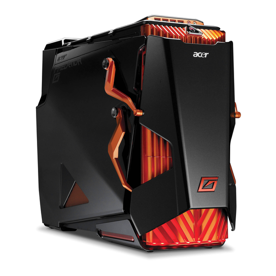
Aspire G7750 Tour This section is a virtual tour of the Aspire G7750 system’s interior and exterior components. Closed Front Panel Item Component Hinge screws x4 Door hinges x4 Bezel door Chapter 1... -
Page 13: Front Panel
Front Panel Item Icon Chapter 1 Component USB 2.0 ports Microphone/speaker-out/line-in jack Headphone/line-out jack Power button/power indicator Optical disk drives XD (eXtreme Digital) slot USB 2.0 port IEEE 1394 port (4-pin) CFI/II (CompactFlash Type I/II) slot Drive bay door Easy-swap hard disk drives (1-4) MS/MS Pro (Memory Stick/Memory Stick Pro Duo) slot SD/MMC (SecureDigital/MultimediaCard) slot Optical disk drive eject buttons... -
Page 14: Rear Panel
Rear Panel Item Icon Component Power supply PS2 mouse port System fan Network ports Rear speaker jack Center speaker/subwoofer jack Expansion slot locks S-video port DVI port Audio-in/line-in jack Headphone/line-out/front speaker jack Microphone/line-in jack S/PDIF jack USB 2.0 ports IEEE 1394 port (6-pin) eSATA (External Serial Advanced Technology Attachment) ports Clear CMOS button PS2 keyboard port... -
Page 15: Internal Components
Internal Components Item Component Liquid cooling system Mainboard System memory Release sliders for optical drives Hard drive backplane board Release sliders for HDD drives Expansion slot lock levers Expansion card System fan Power supply module Chapter 1... -
Page 16: System Led Indicators
System LED Indicators This section describes the different system LED indicators. LED indicator Color Power HDD activity Green Amber Green/ Amber LAN port Orange network activity (left) LAN port Orange network link Green LED (right) LED status Description The system has AC power and is powered on. Blinking The system is in standby mode. -
Page 17: System Utilities
System Utilities CMOS Setup Utility CMOS setup is a hardware configuration program built into the system ROM, called the complementary metal- oxide semiconductor (CMOS) Setup Utility. Since most systems are already properly configured and optimized, there is no need to run this utility. You will need to run this utility under the following conditions. When changing the system configuration settings •... -
Page 18: Entering Cmos Setup
Entering CMOS setup Turn on the server and the monitor. If the server is already turned on, close all open applications, then restart the server. During POST, press Delete. If you fail to press Delete before POST is completed, you will need to restart the server. The Setup Main menu will be displayed showing the Setup’s menu bar. -
Page 19: Setup Utility Menus
Setup Utility Menus The tabs on the Setup menu bar correspond to the six primary CMOS Setup menus, namely: Product Information • Standard CMOS Features • Advanced BIOS Features • Advanced Chipset Features • Integrated Peripherals • Power Management Setup •... -
Page 20: Product Information
Product Information Select the Product Information from the CMOS Setup menu, then press Enter. The basic information about the system appears on the screen. These entries are for your reference only and are not user-configurable. Chapter 2... -
Page 21: Standard Cmos Features
Standard CMOS Features Parameter Description System Date Set the date following the weekday-month-day-year format. System Time Set the system time following the hour-minute-second format. Primary Master/Slave Press Enter to view detailed device information connected to the IDE/SATA/E-SATA connectors. & Serial-ATA 1~6 channel &... -
Page 22: Advanced Bios Features
Advanced BIOS Features Parameter Description Reset Configuration Data Allows you to manually force BIOS to clear the previously saved Extended System Configuration Data (ESCD) data and reconfigure the settings. When set to no, it lets the BIOS configure all the devices in the system. When set to yes, it lets the OS configure Plug and Play (PnP) devices not required for boot if the system has a PnP OS. -
Page 23: Advanced Chipset Features
Advanced Chipset Features Parameter Description Intel EIST Enables or disables the processor speed to be controlled by the OS. Intel XD Bit If disabled, it forces the Execute Disable (XD) Bit feature flag to always return to 0. Intel VT Enabled or disables the Virtualization Technology (VT) availability. -
Page 24: Integrated Peripherals
Integrated Peripherals Parameter Description Onboard SATA Controller Enables or disables the onboard SATA controller. Onboard SATA Mode Select an operating mode for the onboard SATA. SATA 1 to 6 Enables or disables the SATA RAID on ports 1 to 6. Note: This parameter is configurable only if the SATA Mode is set to RAID. -
Page 25: Power Management Setup
Power Management Setup Parameter Description ACPI Suspend Mode Select an ACPI state. Deep Power Off Mode Enables for disables Deep Power off function (deep power off mode reserve only certain power for the CMOS battery and remove other power source such as CPU, memory, WOL function..etc). Power On by RTC Alarm Enables or disables to boot the system on scheduled date/time. -
Page 26: Pc Health Status
PC Health Status Parameter Description CPU Warning Temperature Sets the warning threshold for processor temperature. When processor temperature exceeds the threshold, BIOS will emit warning sound. CPU Shutdown Temperature Sets the processor shutdown temperature. CPU Fan Smart Fan Enables or disables the processor fan speed control function. System Fan1 Smart Fan Enables or disables the system fan 1 speed control function. -
Page 27: Frequency Control
Frequency Control Parameter Description D.O.T. Control Enables or disables Dynamic Overclocking Technology (D.O.T.). DOT detects the load balance of the processor while running programs, and to adjust the best processor frequency automatically. When the system detects the CPU is running programs, it will speed up the processor automatically to make the program run smoothly and faster. - Page 28 Parameter Description Adjust DRAM Configuration Press Enter to access the Adjust DRAM Configuration submenu to override the memory’s Serial Presence Detect (SPD) settings by manually entering values for DRAM timings. Adjust PCI-E Frequency Sets the PCI Express clock frequency. MCP PCI-Express Sets the reference clock for the media and communications processor Frequency, MHz (MCP) PCI Express...
-
Page 29: Bios Security Features
BIOS Security Features The BIOS Security menu allows you to safeguard and protect the system from unauthorized use by setting up access passwords. Parameter Description Supervisor Password Indicates the status of the supervisor password. User Password Indicates the status of the user password. Change Supervisor Supervisor password prevents unauthorized access to the BIOS Setup Utility. - Page 30 Removing a supervisor password Use the up/down arrow keys to select Change Supervisor Password menu then press Enter. Enter the current password then press Enter. Press Enter twice without entering anything in the password fields. Setting a user password Use the up/down arrow keys to select Set User Password menu then press Enter. A password box will appear.
-
Page 31: Load Optimized Defaults
Load Optimized Defaults The Load Optimized Defaults menu allows you to load the default settings for all BIOS setup parameters. Setup defaults are quite demanding in terms of resources consumption. If you are using low-speed memory chips or other kinds of low-performance components and you choose to load these settings, the system might not function properly. - Page 32 Save & Exit Setup The Save & Exit Setup menu allows you to save changes made and close the Setup Utility. Chapter 2...
-
Page 33: Exit Without Saving
Exit Without Saving The Exit Without Saving menu allows you to discard changes made and close the Setup Utility. Chapter 2... - Page 34 Chapter 2...
-
Page 35: System Disassembly
System Disassembly This chapter contains step-by-step procedures on how to disassemble the desktop computer for maintenance and troubleshooting. Disassembly Requirements To disassemble the computer, you need the following tools: Wrist grounding strap and conductive mat for preventing electrostatic discharge • Flat-blade screwdriver •... -
Page 36: Pre-Disassembly Procedure
Pre-disassembly Procedure Before proceeding with the disassembly procedure, perform the steps listed below: Turn off the system and all the peripherals connected to it. Unplug the power cord from the power outlets. Unplug the power cord from the system. Unplug all peripheral cables from the system. Place the system unit on a flat, stable surface. -
Page 37: Main Unit Disassembly
Main Unit Disassembly External Modules Disassembly Flowchart The flowchart below gives you a graphic representation on the entire disassembly sequence and instructs you on the components that need to be removed during servicing. VIDEO CARDS TV TUNER CARD CARD READER BOARD LIQUID COOLER Chapter 3 MAIN UNIT DISASSEMBLY... -
Page 38: Screw List
Screw List Card reader carrier screw Card reader board screw Liquid cooler fan screw MA HEX #6-32 5MM NI Screw HDD carrier screw M#6-32 L4.6 BZN Liquid cooler screw M HEX #6-32 L5 BZN M#6-32 L4.6 BZN M #6-32 L5 BZN Part No. -
Page 39: Removing The Bezel Door
Removing the Bezel Door Perform the pre-disassembly procedure described on page 28. Grasp the front edge of the bezel door, then tilt up until it is aligned with the top panel. Remove the four screws that hold the door hinges to the right side panel (1). Remove the four screws that hold the door hinges to the left side panel (2). -
Page 40: Removing The Hard Disk Drive
Removing the Hard Disk Drive Remove the bezel door. Refer to the previous section for instructions. Open the drive bay door. Press the HDD carrier latch, then pull the lever down to the fully open position. Chapter 3... - Page 41 Pull the carrier out of the drive bay. Place the HDD carrier on a clean, static-free network surface. If you are replacing a hard disk, remove the four screws (A) that secure the hard disk to the carrier. Screw (Quantity) HDD carrier screw (4) Remove the disk from the carrier.
-
Page 42: Removing The Left Side Panel
Removing the Left Side Panel See “Removing the Bezel Door” on page 31. Release the two panel locks on the rear of the left side panel. Hold the rear edge of the panel and slide the panel towards the rear (1), slightly raise the panel then lift the panel away from the chassis (2). -
Page 43: Removing The Right Side Panel
Removing the Right Side Panel See “Removing the Bezel Door” on page 31. Pull the top edge out and slightly lift up to detach the tabs inside the panel (1), then slide the panel towards the rear of the chassis (2). Chapter 3... -
Page 44: Removing The Front Bezel
Removing the Front Bezel See “Removing the Bezel Door” on page 31. See “Removing the Left Side Panel” on page 34. Disconnect the front panel cable from the mainboard. Release the front bezel retention tabs from the chassis interior. Chapter 3... - Page 45 Pull the bezel away from the chassis. Chapter 3...
-
Page 46: Removing The Optical Drive
Removing the Optical Drive See “Removing the Bezel Door” on page 31. See “Removing the Left Side Panel” on page 34. See “Removing the Front Bezel” on page 36. Disconnect the power and data cables from rear of the old drive. Move the release slider of the selected drive to the unlock position, then pull the drive out of the device bay. -
Page 47: Removing The Video Cards
Removing the Video Cards See “Removing the Bezel Door” on page 31. See “Removing the Left Side Panel” on page 34. Lay the system on its side (with components showing). Remove the SLI bridge cable from the video cards, then press down on the expansion slot release latch. Gently pull the card to detach it from the mainboard. - Page 48 Disconnect the power cables from the video cards, then remove the cards. Chapter 3...
-
Page 49: Removing The Tv Tuner Card
Removing the TV Tuner Card See “Removing the Bezel Door” on page 31. See “Removing the Left Side Panel” on page 34. See “Removing the Video Cards” on page 39. Press down on the expansion slot release latch. Gently pull the card to detach it from the mainboard. Chapter 3... -
Page 50: Removing The Card Reader Drive
Removing the Card Reader Drive See “Removing the Bezel Door” on page 31. See “Removing the Left Side Panel” on page 34. See “Removing the Front Bezel” on page 36. Release cables from the retention clip. Disconnect the USB and 1394 cables from the mainboard. Chapter 3... - Page 51 Move the release slider to the unlock position and push the module into the bay, then remove it from the chassis. Chapter 3...
-
Page 52: Removing The Card Reader Board
Removing the Card Reader Board See “Removing the Bezel Door” on page 31. See “Removing the Left Side Panel” on page 34. See “Removing the Front Bezel” on page 36. See “Removing the Card Reader Drive” on page 42. Place the module on a clean, static-free surface. Remove the two screws (B) that secure the cover to the carrier. - Page 53 Remove the card reader carrier cover. Remove the two screws (C) that secure the card reader board to the carrier. Screw (Quantity) Card reader board screw (2) 10. Remove the card reader board from the carrier. Chapter 3 Color Torque Silver Part No.
-
Page 54: Removing The Backplane Board
Removing the Backplane Board See “Removing the Bezel Door” on page 31. See “Removing the Hard Disk Drive” on page 32. See “Removing the Left Side Panel” on page 34. See “Removing the Front Bezel” on page 36. See “Removing the Video Cards” on page 39. Slide the HDD cage slider up, then pull the cage out of the drive bay. - Page 55 Slide the backplane board forward (1) then remove the board from the HDD cage (2). Chapter 3...
-
Page 56: Removing The Memory Modules
Removing the Memory Modules IMPORTANT:Before removing any DIMM from the memory board, make sure to create a backup file of all important data. See “Removing the Bezel Door” on page 31. See “Removing the Left Side Panel” on page 34. Press the holding clips on both sides of the DIMM slot outward to release the DIMM. -
Page 57: Removing The Liquid Cooler Fan Assembly
Removing the Liquid Cooler Fan Assembly WARNING:The heat sink becomes very hot when the system is on. NEVER touch the heat sink with any metal or with your hands. See “Removing the Bezel Door” on page 31. See “Removing the Left Side Panel” on page 34. See “Removing the Front Bezel”... - Page 58 Remove the four screws (E) securing the fan end of the liquid cooler fan assembly to the chassis. Screw (Quantity) Liquid cooler screw (4) Lift the fan and heat exchanger end of the liquid cooler assembly from the chassis, then gently detach the cooler end from the mainboard.
-
Page 59: Removing The Fan From The Liquid Cooler
Removing the Fan from the Liquid Cooler See “Removing the Bezel Door” on page 31. See “Removing the Left Side Panel” on page 34. See “Removing the Liquid Cooler Fan Assembly” on page 49. Remove the four screws (F) that secure the fan to the heat exchanger on the liquid cooler fan assembly and store screws and washer for later use, then detach the fan from the cooler. -
Page 60: Removing The Processor
Removing the Processor IMPORTANT:Before removing a processor from the mainboard, make sure to create a backup file of all important data. WARNING:The processor becomes very hot when the system is on. Allow it to cool off first before handling. See “Removing the Bezel Door” on page 31. See “Removing the Left Side Panel”... - Page 61 Grasp the processor by its edges and lift it out of its socket. IMPORTANT:If you are going to install a new processor, note the arrow on the corner to make sure the processor is properly oriented over the socket. Chapter 3...
-
Page 62: Removing The Power Supply
Removing the Power Supply See “Removing the Bezel Door” on page 31. See “Removing the Left Side Panel” on page 34. See “Removing the Front Bezel” on page 36. See “Removing the Optical Drive” on page 38. See “Removing the Video Cards” on page 39. See “Removing the TV Tuner Card”... - Page 63 14. Remove the four screws (G) that secure the power supply to the chassis. Screw (Quantity) Color Torque Part No. M Hex #6-32 L5 BZN (4) Black 5.5 to 6.5 kgf-cm 86.00J59.A60 15. Lift the power supply module out of the chassis. Chapter 3...
-
Page 64: Removing The Hdd Fan
Removing the HDD Fan See “Removing the Bezel Door” on page 31. See “Removing the Left Side Panel” on page 34. See “Removing the Front Bezel” on page 36. See “Removing the Card Reader Drive” on page 42. Disconnect the fan cable from the mainboard. Remove the four screws (H) that secure the fan to the chassis. -
Page 65: Removing The Top Cover
Removing the Top Cover See “Removing the Bezel Door” on page 31. See “Removing the Left Side Panel” on page 34. See “Removing the Front Bezel” on page 36. See “Removing the Optical Drive” on page 38. See “Removing the Video Cards” on page 39. See “Removing the TV Tuner Card”... -
Page 66: Removing The Usb Board
Removing the USB Board See “Removing the Bezel Door” on page 31. See “Removing the Optical Drive” on page 38. See “Removing the Video Cards” on page 39. See “Removing the TV Tuner Card” on page 41. See “Removing the Card Reader Drive” on page 42. See “Removing the Backplane Board”... - Page 67 14. Turn it over then detach the cables from the USB board. 15. Remove the two screws (I) that secure the board to the bracket. Screw (Quantity) Color Torque Part No. M #6-32 L5 BZN (2) Black 86.00E66.D60 16. Remove the USB board. Chapter 3...
-
Page 68: Removing The Mainboard
Removing the Mainboard See “Removing the Bezel Door” on page 31. See “Removing the Optical Drive” on page 38. See “Removing the Video Cards” on page 39. See “Removing the TV Tuner Card” on page 41. See “Removing the Card Reader Drive” on page 42. See “Removing the Backplane Board”... - Page 69 15. Remove the nine screws (J) that secure the mainboard to the chassis, in the order shown. Screw (Quantity) Color Torque Part No. HEX #6-32 5MM NI (6) Silver 4.5 to 5.5 kgf-cm 86.2G5B6.013 16. Lift the board from the chassis. Chapter 3...
-
Page 70: Removing The Front Foot Stand
Removing the Front Foot Stand See “Removing the Bezel Door” on page 31. See “Removing the Left Side Panel” on page 34. Lay the system on its side (with components showing). Press the tabs on the front foot stand to disengage with the slots on the chassis. Remove the foot stand. -
Page 71: Removing The Rear Foot Stand
Removing the Rear Foot Stand See “Removing the Bezel Door” on page 31. See “Removing the Left Side Panel” on page 34. Lay the system on its side (with components showing). Press the tabs on the rear foot stand to disengage with the slots on the chassis. Remove the foot stand. - Page 72 Chapter 3...
-
Page 73: Hardware Diagnostic Procedure
This chapter provides instructions on how to troubleshoot system hardware problems. Hardware Diagnostic Procedure IMPORTANT:The diagnostic tests described in this chapter are only intended to test Acer products. Non-Acer products, prototype cards, or modified options can give false errors and invalid system response. -
Page 74: System Check Procedures
Verify that components are properly seated. Verify that all cable connectors inside the system are firmly and correctly attached to their appropriate connectors. 10. Verify that all components are Acer-qualified and supported. 11. Replace the system covers. 12. Power on the system. -
Page 75: Post Error And Beep Codes
POST Error and Beep Codes NOTE: Perform the FRU replacement or actions in the sequence shown in FRU/Action column, if the FRU replacement does not solve the problem, put the original part back in the computer. Do not replace a non-defective FRU. - Page 76 POST Code (Hex) Init CPU_FAR OEM BOARD_B_Init KBC8042_FAR Init KBC8042_FAR KBC BatTest_FAR Init KBC8042_FAR Program KBC Command Byte_FAR Init KBC8042_FAR Init KBC8042_FAR Init Input Devices_FAR Detect PS2 Mouse_FAR Init KBC8042_FAR Detect PS2 KeyBoard_FAR Init KBC8042_FAR OEM BOARD_A_OEM_ReCalcCPUFreq_FAR Init Input Devices_FAR Init Input Devices_FAR Check Install POST INT09hHandler_FAR Init Input Devices_FAR...
- Page 77 POST Code (Hex) CRB_Init At Early POST_FAR Cp Init At Early POST_FAR Init GPNV Area_FAR Init BIOS Modules_FAR Process SMBIOS Module_far Init GPNV Area_FAR Init Language Modules_FAR Init BIOS Modules_FAR Init Osb CMOS_FAR Init Silent Logo Module_FAR Init Silent Logo Module_FAR Init BIOS Modules_FAR Save OEM LOGO Size_FAR Init Silent Logo Module_FAR...
- Page 78 POST Code (Hex) FLASH Recovery From New ROM_FAR Display BIOS Logo_FAR OEM BOARD_R_Display Sign On Msg_FAR Display Sign On Msg_FAR OEM BOARD_R_Display CPU Info_FAR Display CPU Info_FAR Display CrLf_FAR Display CPU Info_FAR Cp Display BIOS Info_FAR Display BIOS Info_FAR NB_Display BIOS Info_FAR Cp Display BIOS Info_FAR OEM BOARD_R_Display Memory Info_FAR NB_Display BIOS Info_FAR...
- Page 79 POST Code (Hex) CPU_Special_Do farSIOITE8718HHM Common Register Init u6262_B_CpInit At Early farSIOITE8718HHM Common Register Init Hardware_security_FAR farSIOITE8718HHM Common Register Init Special_Marvel_PME_Patch farSIOITE8718HHM Common Register Init far Enable USB Data Area far Init USB HC far Init USB HC DIM Device Init At Mid POST_FAR Check Install POST INT 09h Handler_FAR far Init USB HC Validate Attached USB Mass Devices...
- Page 80 POST Code (Hex) Detect Serial Ports_FAR Global Device Init At Mid POST_FAR Detect Coprocessor_FAR Global Device Init At Mid POST_FAR Detect System RAM_FAR Global Device Init At Mid POST_FAR Init KB CAt Mid POST_FAR Global Device Init At Mid POST_FAR Clear BIOS Version Info_FAR Init IPL Devices_FAR far Display USB Devices...
- Page 81 POST Code (Hex) Get Last Sys Config GPNV_FAR Init IPL Devices_FAR BBS Build Tables_FAR Init IPL Devices_FAR Store New Sys Config GPNV_FAR Init IPL Devices_FAR BBS Connect Drives_FAR Init IPL Devices_FAR Restore Shadow State_FAR Init IPL Devices_FAR BBS Finale_FAR Init IPL Devices_FAR Restore Display Mode_FAR Init IPL Devices_FAR SB_Before_Setup_Check_VT...
- Page 82 POST Code (Hex) Prepare E820Table_FAR Global Device Init At Late POST_FAR Global Device Init At LatePOST_FAR Cp Init At Late POST_FAR Global Device Init At Late POST_FAR NB_Init At Late POST_FAR Cp Init At Late POST_FAR SB_Init At Late POST_FAR Cp Init At Late POST_FAR OEM_Init At Late POST_FAR Cp Init At Late POST_FAR...
- Page 83 POST Code (Hex) Uninstall POST INT 1Ch Handler_FAR Prepare System For OS_FAR Clear KBD Buffer_Far Uninstall POST INT09h Handler_FAR SB_Clear KBD Buffer_FAR Clear KBD Buffer_Far Uninstall POST INT09h Handler_FAR Prepare System For OS_FAR BBS BeforeI19_FAR Uninstall POST INT09h Handler_FAR ACPIS4Set Boot Drive_FAR BBS BeforeI19_FAR OEM BOARD_A_Prepare System For OS_FAR Prepare System For OS_FAR...
- Page 84 POST Code (Hex) Mrm Save Cpu Msr Context_FAR Init At End POST_FAR P4 Save Cpu Msr Context_FAR Init At End POST_FAR ATAC_Init Before Int19_FAR Init At End POST_FAR Init At End POST_FAR POST Routine Description Chapter 4...
-
Page 85: Online Support Information
This section describes online technical support services available to help you repair the desktop computer. If you are a distributor, dealer, ASP or TPM, please refer your technical queries to your local Acer branch office. Acer Branch Offices and Regional Business Units may access our website at http://global.acer.com/ support/index. - Page 86 Chapter 4...
-
Page 87: System Block Diagram
Chapter 5 System Block Diagram and Board Layout System Block Diagram Chapter 5... -
Page 88: Board Layout
Board Layout Mainboard Code Component PWR1 Power connector CPUFAN1 Processor fan cable connector DIMM1-6 System memory slots JPWR1 24-pin ATX power connector SATA1-6 SATA data cable connectors SYSFAN1-5 System fan cable connector F_PANEL1 Front panel connector JUSB1-3 Front USB connectors J1394_1 IEEE 1394 connector JAUD1... -
Page 89: Back Panel I/O
Back Panel I/O Mouse Keyboard Clear CMOS Button Code Color Mouse Green Keyboard Purple 1394 port Optical S/PDIF-out jack eSATA ports Blue Clear CMOS Button LAN Jacks USB ports CS-Out Orange RS-Out Black SS-Out Blue Line-In Blue Line-Out Green Pink LAN LED Definition The standard RJ-45 LAN jack is for connection to the Local Area Network (LAN). -
Page 90: System Switches And Jumpers
System Switches and Jumpers Serial ATA Connectors The six serial ATA connectors (SATA1-6) is a high-speed Serial ATA interface port. Each connector can connect to one Serial ATA device. SATA1~6 stack SATA connectors are supported by ICH10R SATA1_3 SATA2_4 SATA5_6 IMPORTANT:Please do not fold the Serial ATA cable into 90-degree angle. -
Page 91: Ieee 1394 Connector
IEEE 1394 Connector This connector (J1394_1) allow you to connect the IEEE1394 device via an optional IEEE1394 bracket. Front Panel Connector These connectors (F_PANEL1) are for electrical connection to the front panel switches and LEDs. Pin Definition Chapter 5 J1394_1 Signal TPA+ Ground... -
Page 92: Front Usb Connector
Front USB Connector The front USB connectors (JUSB1, JUSB2, and JUSB3), compliant with Intel(R) I/O Connectivity Design Guide, is ideal for connecting high-speed USB interface peripherals such as USB HDD, digital cameras, MP3 play connects to high-speed USB interface peripherals. Chassis Intrusion Connector The chassis intrusion connector (JCI1) connects to the chassis intrusion switch cable. -
Page 93: Power Connectors
Power Connectors The ATX 24-pin power connector (JPWR1) allows you to connect an ATX 24-pin or ATX 20-pin power supply. When using a 20-pin ATX power supply, plug the power supply along with pins 1 and 13. A foolproof design is on pins 11, 12, 23, and 24 to avoid wrong installation. -
Page 94: Cmos Reset Button
CMOS Reset Button The CMOS reset button located on the rear of the system, is powered by a battery on board to keep the system configuration data. The CMOS RAM records the correct time and setting of system hardware configuration. With the CMOS RAM, the system can automatically boot OS every time it is turned on. If you want to clear the system configuration, use the CMOS reset button to clear data. -
Page 95: Fru (Field Replaceable Unit) List
To scrap or to return the defective parts, follow the local government ordinance or regulations on • how to dispose it properly, or follow the rules set by your regional Acer office on how to return it. This document will be updated as more information about the FRU list becomes available. -
Page 96: Aspire G7710 Series Exploded Diagram
Aspire G7750 Series Exploded Diagram Chapter 6... - Page 97 ITEM PART NO. 60.3V218.002 86.00J10.A60 23.10240.001 33.3V207.001 54.13042.001 33.3V209.001 86.00E66.D60 42.3V218.001 60.3V208.001 60.3V212.001 60.3V207.001 42.3V203.001 42.3V204.001 33.3V205.001 50.3V203.001 42.3V229.001 42.3V223.001 42.3V222.001 42.3V224.001 42.3V226.001 42.3V225.001 60.3V210.001 60.3V220.001 42.3V201.001 60.3V209.001 60.3V217.001 60.3V216.001 60.3V204.001 33.3V203.001 60.3V205.001 42.3V230.001 42.3V201.001 42.3V202.001 60.3V206.001 60.3V213.001 42.3V231.001 60.3V215.001 60.3V214.001 Chapter 6 PART NAME...
- Page 98 Aspire G7750 Series Note: Please refer to service BOM for correct part number. The information hereafter is for your reference only. Component System board CPU Intel Core i7 940 2.93G 8M 1066 130W C-0 Quad- Core, LGA1366 CPU Intel Core i7 940 2.93G...
- Page 99 WD HDD WD 750GB SATA 8MB 7200 NCQ HGST 1TB SATA 8MB 7200 NCQ ASSY BRKT 4HSP HDD CAGE AG900 ASSY HDD CARRIER SATA AG900 Description Part Number PY.75009.001 81.3V210.002G 81.3V210.003G 81.3V210.004G CR.10400.008 CR.10400.009 KU.0160D.034 KU.01609.005 KU.0160E.002 KV.0040D.001 KH.25008.020 KH.32008.014 KH.50007.003 KH.75007.001 KH.75008.001 KH.01K07.001 60.3V216.001 60.3V217.001 Acer...
- Page 100 HINGE FRONT COVER LEFT 2 HINGE FRONT COVER RIGHT 1 HINGE FRONT COVER RIGHT 2 HOLDER POWER KNOB C.A. LED SWITCH CABLE Description Part Number 60.3V202.001 60.3V204.001 60.3V205.001 60.3V206.001 60.3V214.001 60.3V207.001 60.3V210.001 60.3V208.001 60.3V209.001 42.3V201.001 42.3V202.001 42.3V203.001 42.3V204.001 42.3V229.001 50.3V203.001 Acer Chapter 6...
- Page 101 ACCESSORY TRAY EPE BUMBLEBEE SHEET PE 1600*1600*0.04 CORNER KRAFT 1000*50*50*3 M1KC PAPER CORNER 2200*50*50*3 PALLET PLYWOOD 1350*1140*135MM Description Part Number 27.01518.0J1 27.03118.031 27.01518.0R1 27.01518.181 27.01518.0N1 27.01518.0M1 27.01518.0I1 27.01518.0K1 NI.10200.002 42.3ZM.07.002 44.3V201.011 44.3V202.011 47.3V201.001 47.3V202.001 47.3V208.001 47.3V210.001 47.3V211.001 42.73D05.001 46.30S04.001 46.3ZT01.001 47.3V209.001 Acer...
- Page 102 Chapter 6...
-
Page 103: Appendix A Technical Specifications
Technical Specifications This section provides technical specifications for the system. For Processor, memory and optical drive specification, please double click AVLC attached for more informtion. AVLC Processor Item Specification Type Intel Core 2 Extreme Model Number QX9650 Core Quad (45 nm) L2 Cache Size (MB) Clock Speed (GHz) Front Side Bus (MHz) 1333... - Page 104 Item Specification Pin count System BIOS Item BIOS vendor PCI Interface Item PCI controller Number of slots Network Interface Item LAN controller Supports LAN protocol LAN connector type SATA Interface Item SATA controller Connectors Audio Interface Item Audio controller Connectors Specification American Megatrends Inc.
- Page 105 IEEE 1394 Interface Item IEEE 1394 controller Connectors Optical Drive BD-R Item Vendor Model name Drive type Write Speed Read Speed Data Transfer Rate Access Time Buffer Size Interface Type Appendix A Specification VIA 6315N 1394a controller 1 rear 6pin IEEE1394 port 1 2x5pin on board jumper Specification HLDS...
- Page 106 Super Multi Item Vendor Model name Drive type Write Speed Read Speed Data Transfer Rate Access Time Buffer Size Interface Type Specification HLDS Philips GH-15N DH-16A3S Super Multi Super Multi — — — — — — — — 4 MB 4 MB Serial ATA Serial ATA...
-
Page 107: Appendix B Test Compatible Components
Appendix B Test Compatible Components This computer’s compatibility is tested and verified by Acer’s internal testing department. All of its system functions are tested under the following environment: Genuine Windows 7 Home Premium (64-bit) • Appendix B... - Page 108 Refer to the following lists for components, adapter cards, and peripherals which have passed these tests. Double click AVLC list. Appendix B...