Table of Contents
Advertisement
Quick Links
Advertisement
Table of Contents

Related Manuals for Asus KFSN5-D


Summary of Contents for Asus KFSN5-D
- Page 1 KFSN5-D...
- Page 2 Product warranty or service will not be extended if: (1) the product is repaired, modified or altered, unless such repair, modification of alteration is authorized in writing by ASUS; or (2) the serial number of the product is defaced or missing.
-
Page 3: Table Of Contents
Contents Notices ......................vii Safety information ..................viii About this guide ..................ix Typography ....................x KFSN5-D specifications summary ............xi Chapter 1: Product introduction Welcome! ..................1-1 Package contents ................. 1-1 Serial number label ..............1-2 Special features ................1-2 1.4.1... - Page 4 Contents 2.5.6 PCI slot ................. 2-16 2.5.8 SODIMM socket ............2-16 2.5.9 Installing ASUS PIKE RAID card ........2-17 2.5.10 Installing i Button ............2-17 Jumpers ..................2-18 Connectors ................. 2-22 2.7.1 Rear panel connectors ..........2-22 2.7.2 Internal connectors ............2-23...
- Page 5 Contents 4.3.5 System Information ............4-12 Advanced menu ................. 4-14 4.4.1 CPU Configuration ............4-14 4.4.2 Chipset Configuration ........... 4-15 4.4.3 PCI/PnP Configuration ..........4-22 4.4.4 USB Configuration ............4-24 4.4.5 ACPI Configuration ............4-25 4.4.6 Peripheral Devices Configuration ......... 4-26 4.4.7 Power On Configuration ..........
- Page 6 Management applications and utilities installation ....6-16 6.4.1 Running the support CD ..........6-16 6.4.2 Drivers menu ..............6-16 6.4.3 Management Software menu ........6-17 6.4.4 Utilities menu ..............6-17 6.4.5 Contact information ............6-17 Appendix: Reference information KFSN5-D block diagram ..............A-1...
-
Page 7: Notices
Notices Federal Communications Commission Statement This device complies with Part 15 of the FCC Rules. Operation is subject to the following two conditions: • This device may not cause harmful interference, and • This device must accept any interference received including interference that may cause undesired operation. -
Page 8: Safety Information
Safety information Electrical safety • To prevent electrical shock hazard, disconnect the power cable from the electrical outlet before relocating the system. • When adding or removing devices to or from the system, ensure that the power cables for the devices are unplugged before the signal cables are connected. -
Page 9: About This Guide
Refer to the following sources for additional information and for product and software updates. ASUS websites The ASUS website provides updated information on ASUS hardware and software products. Refer to the ASUS contact information. Optional documentation Your product package may include optional documentation, such as warranty flyers, that may have been added by your dealer. -
Page 10: Typography
Conventions used in this guide To make sure that you perform certain tasks properly, take note of the following symbols used throughout this manual. DANGER/WARNING: Information to prevent injury to yourself when trying to complete a task. CAUTION: Information to prevent damage to the components when trying to complete a task. -
Page 11: Kfsn5-D Specifications Summary
KFSN5-D specifications summary Model Name KFSN5-D Processor Support / System Bus 2 * socket 1207 Quad-Core AMD Opteron™ 2300 series (Barcelona) Dual-Core AMD Opteron™ 2200 series HyperTransport™ Technology 1.0, 1GHz 2x1M L2 cache Core Logic nVIDIA nForce Professional 3600 Form Factor SSI EEB Compliant, 12"x13"... - Page 12 Non operation humidity: 20% ~ 90% ( Non condensing) ® • MegaRAID function is available only when you install ASUS PIKE 1078 RAID card with iBTN. • The onboard IDE connector is designed for ODD only (PATA). *Specifications are subject to change without notice.
-
Page 13: Chapter 1: Product Introduction
This chapter describes the motherboard features and the new technologies it supports. Product introduction... - Page 14 Chapter summary Welcome! ..................1-1 Package contents ................. 1-1 Serial number label ..............1-2 Special features ................1-2 ASUS KFSN5-D...
-
Page 15: Welcome
KFSN5-D motherboard! The motherboard delivers a host of new features and latest technologies, making it another standout in the long line of ASUS quality motherboards! Before you start installing the motherboard, and hardware devices on it, check the items in your package with the list below. -
Page 16: Serial Number Label
Before requesting support from the ASUS Technical Support team, you must take note of the motherboard's serial number containing 12 characters xxM0Axxxxxxx shown as the figure below. With the correct serial number of the product, ASUS Technical Support team members can then offer a quicker and satisfying solution to your problems. -
Page 17: Innovative Asus Features
1.4.2 Innovative ASUS features ASUS Smart Fan II technology The ASUS Smart Fan technology smartly adjusts the fan speeds according to the system loading to ensure quiet, cool, and efficient operation. ASUS KFSN5-D... - Page 18 PIKE (Proprietary I/O Kit Expansion) PIKE is an on-demand upgrade kit for users. This ASUS unique feature enables users to choose their preferred I/O solutions. ASUS provides multiple SAS solutions for different segments and purposes and PIKE saves lots of validation efforts and hardware cost for end users.
-
Page 19: Chapter 2: Hardware Information
This chapter lists the hardware setup procedures that you have to perform when installing system components. It includes description of the jumpers and connectors on the motherboard. Hardware information... - Page 20 Chapter summary Before you proceed ..............2-1 Motherboard overview ..............2-3 Central Processing Unit (CPU) ........... 2-7 System memory ................. 2-11 Expansion slots ................2-14 Jumpers ..................2-18 Connectors ................. 2-22 ASUS KFSN5-D...
-
Page 21: Before You Proceed
ON, in sleep mode, or in soft-off mode. This is a reminder that you should shut down the system and unplug the power cable before removing or plugging in any motherboard component. The illustration below shows the location of the onboard LED ASUS KFSN5-D... - Page 22 CPU warning LED (CPU_WARN1) The CPU warning LED lights up to indicate that a processor is not installed or the processor is not installed properly in CPU 1 socket. Chapter 2: Hardware information...
-
Page 23: Motherboard Overview
Screw holes Place eleven (11) screws into the holes indicated by circles to secure the motherboard to the chassis. DO NOT overtighten the screws! Doing so can damage the motherboard. Place this side towards the rear of the chassis ASUS KFSN5-D... -
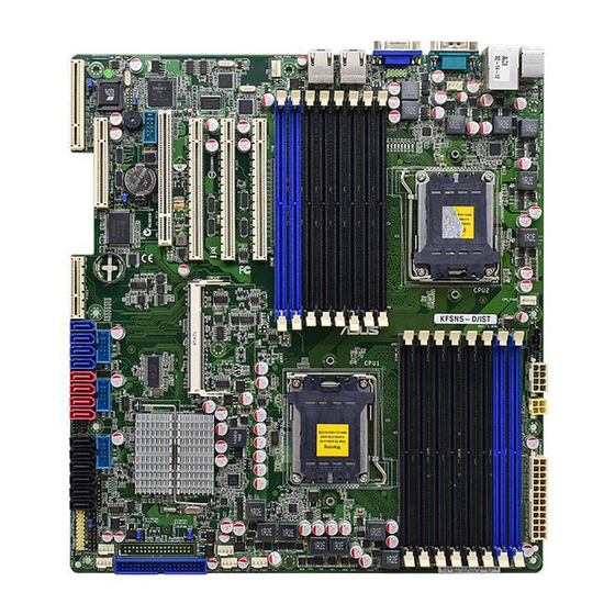
Page 24: Motherboard Layouts
2.2.4 Motherboard layouts Chapter 2: Hardware information... -
Page 25: Layout Contents
PS/2 mouse port (green) 2-22 RJ-45 port for iKVM 2-22 PS/2 keyboard port (purple) 2-22 USB 2.0 ports 1 and 2 2-22 Serial (COM1) port 2-22 Video Graphics Adapter port 2-22 LAN 1 (RJ-45) port 2-22 LAN 2 (RJ-45) port 2-22 ASUS KFSN5-D... - Page 26 Internal connectors Page Floppy disk drive connector (34-1 pin FLOPPY1) 2-23 Serial ATA connectors 2-23 (7-pin SATA1, SATA2, SATA3, SATA4, SATA5, SATA6) IDE connector (40-1 pin PRI_IDE1) 2-24 SAS connectors (7-pin SAS1, SAS2, SAS3, SAS4; Red) 2-25 (7-pin SAS5, SAS6, SAS7, SAS8; Blue) Hard disk activity LED connector (4-pin HDLED1) 2-25 USB connectors (10-1 pin USB34, USB56, USB78)
-
Page 27: Central Processing Unit (Cpu)
ASUS shoulders the repair cost only if the damage is shipment/transit-related. • Keep the cap after installing the motherboard. ASUS will process Return Merchandise Authorization (RMA) requests only if the motherboard comes with the cap on the Socket 1207. - Page 28 Press the load lever with your thumb (A), then move it to the left (B) until it is released from the retention tab. Retention tab PnP cap Load lever This side of the socket box should face you. To prevent damage to the socket pins, do not remove the PnP cap unless you are installing a CPU.
- Page 29 The CPU fits in only one correct orientation. DO NOT force the CPU into the socket to prevent bending the connectors on the socket and damaging the CPU! Close the load plate (A), then push the load lever (B) until it snaps into the retention tab. ASUS KFSN5-D...
-
Page 30: Installing The Heatsink
2.3.2 Installing the heatsink The AMD Opteron™ 2000 series processors require a specially designed heatsink to ensure optimum thermal condition and performance. Ensure to use qualified heatsink assembly only. Follow these steps to install the CPU heatsink. Place the heatsink on top of the installed CPU, making sure that the screw holes are matched with the heatsink standoffs. -
Page 31: System Memory
A DDR2 module has the same physical dimensions as a DDR DIMM but has a 240-pin footprint compared to the 184-pin DDR DIMM. DDR2 DIMMs are notched differently to prevent installation on a DDR DIMM socket. The figure illustrates the location of the DDR2 DIMM sockets: ASUS KFSN5-D 2-11... -
Page 32: Memory Configurations
2.4.2 Memory Configurations You may install 256 MB, 512 MB, 1 GB, 2 GB, or 4 GB registered ECC DDR2 DIMMs into the DIMM sockets using the memory configurations in this section. • For dual-channel configuration, the total size of memory module(s) installed per channel must be the same for better performance. -
Page 33: Installing A Dimm
DIMM. Support the DIMM lightly with your fingers when pressing the retaining clips. The DIMM might DDR2 DIMM notch get damaged when it flips out with extra force. Remove the DIMM from the socket. ASUS KFSN5-D 2-13... -
Page 34: Expansion Slots
Expansion slots In the future, you may need to install expansion cards. The following sub-sections describe the slots and the expansion cards that they support. Make sure to unplug the power cord before adding or removing expansion cards. Failure to do so may cause you physical injury and damage motherboard components. -
Page 35: Interrupt Assignments
ACPI Mode when used IRQ Holder for PCI Steering IRQ Holder for PCI Steering PS/2 Compatible Mouse Port Numeric Data Processor Primary IDE Channel Secondary IDE Channel * These IRQs are usually available for ISA or PCI devices. ASUS KFSN5-D 2-15... -
Page 36: Pci Express X16 Slots (X16 Link; X8 Link)
PCI 2.3 specifications. 2.5.7 PIKE slot The PIKE slot allows you to choose and change your preferred SAS solution easily. Install an optional ASUS PIKE RAID card based on your needs. PCIEx16 slot PCIEx16 slot PCIEx16 slot PCI slot... -
Page 37: Installing Asus Pike Raid Card
2.5.9 Installing ASUS PIKE RAID card Follow the steps below to install an optional ASUS RAID card on your motherboard. Locate the PIKE RAID card slot on the motherboard. Align the golden fingers of the RAID card with the PIKE RAID card slot. -
Page 38: Jumpers
Jumpers Clear RTC RAM (CLRTC1) This jumper allows you to clear the Real Time Clock (RTC) RAM in CMOS. You can clear the CMOS memory of date, time, and system setup parameters by erasing the CMOS RTC RAM data. The onboard button cell battery powers the RAM data in CMOS, which include system setup information such as system passwords. - Page 39 If you use a 4-pin fan but set the jumper to pin 2-3, the fan you installed may not work. • If you use a 3-pin fan but set the jumper for a 4-pin fan, the fan controll will not work and the fan you installed will always run at full speed. ASUS KFSN5-D Series 2-19...
- Page 40 System Fan control setting (3-pin FAN_SEL1) This jumper allows you to switch for fan pin selection. The FAN_SEL1 jumper is for the system fans control. Set to pins 1–2 when using 4-pin fans or pins 2–3 when using 3-pin fans. –...
- Page 41 (XXXXXX.ROM) and the AFUDOS.EXE utility. Set the jumper to pins 2–3. Insert the floppy disk then turn on the system to update the BIOS. Shut down the system. Set the jumper back to pins 1–2. Turn on the system. ASUS KFSN5-D Series 2-21...
-
Page 42: Connectors
Connectors 2.7.1 Rear panel connectors PS/2 mouse port (green). This port is for a PS/2 mouse. RJ-45 port for iKVM. This RJ-45 port functions only when you install ASMB3/iKVM management card. PS/2 keyboard port (purple). This port is for a PS/2 keyboard. USB 2.0 ports 1 and 2. -
Page 43: Internal Connectors
If you installed Serial ATA hard disk drives, you can create a RAID 0, RAID 1, RAID 10, RAID 5, or JBOD configuration. The actual data transfer rate depends on the speed of Serial ATA hard disks installed. ASUS KFSN5-D Series 2-23... - Page 44 IDE connector (40-1 pin PRI_IDE1) This connector is for an Ultra DMA 133/100/66 signal cable. The Ultra DMA 133/100/66 signal cable has three connectors: a blue connector for the primary IDE connector on the motherboard, a black connector for an Ultra DMA 133/100/66 IDE slave device (optical drive/hard disk drive), and a gray connector for an Ultra DMA 133/100/66 IDE master device (hard disk drive).
- Page 45 This LED connector is for the storage add-on card cable connected to the SCSI or SATA add-on card. The read or write activities of any device connected to the SCSI or SATA add-on card causes the front panel LED to light up. ASUS KFSN5-D Series 2-25...
- Page 46 DO NOT forget to connect the fan cables to the fan connectors. Insufficient air flow inside the system may damage the motherboard components. • These are not jumpers! DO NOT place jumper caps on the fan connectors! • All fans feature the ASUS Smart Fan technology. 2-26 Chapter 2: Hardware information...
- Page 47 Serial General Purpose Input/Output connectors (8-1 pin SGPIO2/3) These connector is used for the SAS chip SGPIO interface that controls the LED pattern generation, device information and general purpose data. These connectors functions only when you install a PIKE SAS RAID card. ASUS KFSN5-D Series 2-27...
- Page 48 10. Serial port connector (10-1 pin COM2) This connector is for a serial (COM) port. Connect the serial port module cable to this connector, then install the module to a slot opening at the back of the system chassis. 11. Power Supply SMBus connector (5-pin PSUSMB1) This connector allows you to connect SMBus (System Management Bus) to the power supply unit to read PSU information.
- Page 49 The system may become unstable or may not boot up if the power is inadequate. • Ensure that your power supply unit (PSU) can provide at least the minimum power required by your system. ASUS KFSN5-D Series 2-29...
- Page 50 13. System panel connector (20-pin PANEL1) This connector supports several chassis-mounted functions. System power LED (3-pin PLED) This 3-pin connector is for the system power LED. Connect the chassis power LED cable to this connector. The system power LED lights up when you turn on the system power, and blinks when the system is in sleep mode.
- Page 51 Connect the Locator LED cables to these 2-pin connector. The LEDs will light up when the Locator button is pressed. Locator Button/Swich (2-pin LOCATORBTN) These leads are for the locator button on the front panel. This button queries the state of the system locator. ASUS KFSN5-D Series 2-31...
- Page 52 2-32 Chapter 2: Hardware information...
-
Page 53: Chapter 3: Powering Up
This chapter describes the power up sequence, and ways of shutting down the system. Powering up... - Page 54 Chapter summary Starting up for the first time ............3-1 Turning off the computer ............. 3-2 ASUS KFSN5-D...
-
Page 55: Starting Up For The First Time
Check the jumper settings and connections or call your retailer for assistance. At power on, hold down the <Del> key to enter the BIOS Setup. Follow the instructions in Chapter 4. ASUS KFSN5-D Series... -
Page 56: Powering Off The Computer
Powering off the computer 3.2.1 Using the OS shut down function ® If you are using Windows 2000/2003 Server: Click the Start button then click Shut Down. Select Shut Down from the What do you want the computer to do? list box. Select Shutdown Event Tracker. -
Page 57: Chapter 4: Bios Setup
This chapter tells how to change the system settings through the BIOS Setup menus. Detailed descriptions of the BIOS parameters are also provided. BIOS setup... - Page 58 Chapter summary Managing and updating your BIOS ..........4-1 BIOS setup program ..............4-6 Main menu ..................4-9 Advanced menu ................. 4-14 Server menu ................4-30 Security menu ................4-32 Boot menu .................. 4-34 Exit menu ..................4-36 ASUS KFSN5-D...
-
Page 59: Managing And Updating Your Bios
AFUDOS utility (Updates the BIOS in DOS mode using a bootable floppy disk.) ASUS CrashFree BIOS 3 (To recover the BIOS using a bootable floppy disk when the BIOS file fails or gets corrupted.) Refer to the corresponding sections for details on these utilities. -
Page 60: Afudos Utility
Extension name Press <Enter>. The utility copies the current BIOS file to the floppy disk. A:\>afudos /oOLDBIOS1.rom AMI Firmware Update Utility - Version 1.19(ASUS V2.07(03.11.24BB)) Copyright (C) 2002 American Megatrends, Inc. All rights reserved. Reading flash ..done Write to file..ok A:\>... - Page 61 Updating the BIOS file To update the BIOS file using the AFUDOS utility: Visit the ASUS website (www.asus.com) and download the latest BIOS file for the motherboard. Save the BIOS file to a bootable floppy disk. Write the BIOS filename on a piece of paper. You need to type the exact BIOS filename at the DOS prompt.
- Page 62 The utility returns to the DOS prompt after the BIOS update process is completed. Reboot the system from the hard disk drive. A:\>afudos /i8036A0.ROM AMI Firmware Update Utility - Version 1.19(ASUS V2.07(03.11.24BB)) Copyright (C) 2002 American Megatrends, Inc. All rights reserved. WARNING!! Do not turn off power during flash BIOS Reading file ..
-
Page 63: Asus Crashfree Bios 3 Utility
4.1.3 ASUS CrashFree BIOS 3 utility The ASUS CrashFree BIOS 3 is an auto recovery tool that allows you to restore the BIOS file when it fails or gets corrupted during the updating process. You can update a corrupted BIOS file using a floppy disk or a USB flash drive that contains the updated BIOS file. -
Page 64: Bios Setup Program
The BIOS setup screens shown in this section are for reference purposes only, and may not exactly match what you see on your screen. • Visit the ASUS website (www.asus.com) to download the latest BIOS file for this motherboard. Chapter 4: BIOS setup... -
Page 65: Bios Menu Screen
At the bottom right corner of a menu screen are the navigation keys for that particular menu. Use the navigation keys to select items in the menu and change the settings. Some of the navigation keys differ from one screen to another. ASUS KFSN5-D... -
Page 66: Menu Items
4.2.4 Menu items The highlighted item on the menu bar displays the specific Use [ENTER], [TAB] System Time [11:17:09] System Date [Thu 06/05/2008] or [SHIFT-TAB] to items for that menu. For Floppy A [1.44 MB 3½”] select a field. IDE Configuration Use [+] or [-] to example, selecting Main shows configure system... -
Page 67: Main Menu
Allows you to set the system date. 4.3.3 Floppy A [1.44 MB 3½”] Sets the type of floppy drive installed. Configuration options: [Disabled] [360 KB, 5 ”] [1.2 MB, 5 ”] [720 KB, 3 ”] [1.44 MB, 3 ”] [2.88 MB, 3 ”] ASUS KFSN5-D... -
Page 68: Ide Configuration
4.3.4 IDE Configuration The items in this menu allow you to set or change the configurations for the IDE devices installed in the system. Select an item then press <Enter> if you wish to configure the item. BIOS SETUP UTILITY Main IDE Configuration DISABLED: disables the... - Page 69 DMA Mode [Auto] Sets the DMA mode. Configuration options: [Auto] [SWDMA0] [SWDMA1] [SWDMA2] [MWDMA0] [MWDMA1] [MWDMA2] [UDMA0] [UDMA1] [UDMA2] [UDMA3] [UDMA4] [UDMA5] S.M.A.R.T. [Auto] Sets the Smart Monitoring, Analysis, and Reporting Technology. Configuration options: [Auto] [Disabled] [Enabled] ASUS KFSN5-D 4-11...
-
Page 70: System Information
System Information This menu gives you an overview of the general system specifications. The BIOS automatically detects the items in this menu. BIOS SETUP UTILITY Main System Information Model Name ASUS KFSN5-D Model ID 8068A0 ASUS-BIOS Version 1000.016 Date 05/09/2008... - Page 71 1024MB CPU1 Memory Configuration CPU1 Memory Configuration CPU1/2 Memory Configuration Displays the auto-detected memory specification. BIOS SETUP UTILITY Main CPU1 Memory Configuration Speed DDR2 533 DIMM_A1 DIMM_B1 DIMM_A2 DIMM_B2 DIMM_A3 DIMM_B3 DIMM_A4 512 MB DIMM_B4 512 MB ASUS KFSN5-D 4-13...
-
Page 72: Advanced Menu
Advanced menu The Advanced menu items allow you to change the settings for the CPU and other system devices. Take caution when changing the settings of the Advanced menu items. Incorrect field values can cause the system to malfunction. BIOS SETUP UTILITY Main Advanced Server... -
Page 73: Chipset Configuration
Enter Go to Sub Screen Min Active RAS(Tras) :11 CLK, 11 CLK General Help RAS/RAS Delay(Trrd) :2 CLK, 2 CLK Save and Exit Row Cycle (Trc) :15 CLK, 15 CLK Exit V02.61 (C)Copyright 1985-2006, American Megatrends, Inc. ASUS KFSN5-D 4-15... - Page 74 Memory Configuration The memory configuration menu allows you to change the memory settings. BIOS SETUP UTILITY Advanced Memory Configuration Enable Bank Memory Interleaving Bank Interleaving [Auto] Node Interleaving [Disabled] Memory Hole Remapping [Enabled] DCT Unganged Mode [Always] Power Down Enable [Enabled] Power Down Mode [Channel]...
- Page 75 [2.56us] [5.12us] [10.2us] [20.5us] [41.0us] [81.9us] [163.8us] [327.7us] [655.4us] L3 Cache BG Scrub [Disabled] Enabling this tem corrects the L3 data cache ram when it is idle. Configuration options: [Disabled] [40ns] [80ns] [160ns] [320ns] [640ns] [1.28us] [2.56us] [5.12us] [10.2us] [20.5us] [41.0us] [81.9us] [163.8us] [327.7us] [655.4us] ASUS KFSN5-D 4-17...
- Page 76 DRAM Timing Configuration BIOS SETUP UTILITY Main Advanced DRAM Timing Configuration Options Memory Clock Mode [Auto] Auto DRAM Timing Mode [Auto] Limit Manual Memory Clock Mode [Auto] Configuration options: [Auto] [Limit] [Manual] The following item appears when Memory Clock Mode is set to [Limit] or [Manual].
- Page 77 Configuration options: [2 CLK] [3 CLK] [4 CLK] [5 CLK] [Reserved] [Auto] tWTR [Auto] Configuration options: [1 CLK] [2 CLK] [3 CLK] [Reserved] [Auto] tRFC0 [Auto] Configuration options: [Auto] [75ns] [105ns] [127.5ns] [195ns] [327.5ns] tRFC1 [Auto] Configuration options: [Auto] [75ns] [105ns] [127.5ns] [195ns] [327.5ns] ASUS KFSN5-D 4-19...
- Page 78 tRFC2 [Auto] Configuration options: [Auto] [75ns] [105ns] [127.5ns] [195ns] [327.5ns] tRFC3 [Auto] Configuration options: [Auto] [75ns] [105ns] [127.5ns] [195ns] [327.5ns] IOMMU Option Menu BIOS SETUP UTILITY Main Advanced Set GART size in IOMMU Option Menu systems without AGP, or disable altogether. IOMMU Mode [Disabled] Some OSes require...
- Page 79 Change Option General Help Save and Exit Exit V02.61 (C)Copyright 1985-2006, American Megatrends, Inc. Active State Power-Management [Disabled] Allows you to enable or disable the PCI Express L0s and L1 link power management. Configuration options: [Disabled] [Enabled] ASUS KFSN5-D 4-21...
-
Page 80: Pci/Pnp Configuration
4.4.3 PCI/PnP Configuration The PCI/PnP Configuration menu items allow you to change the advanced settings for PCI/PnP devices. The menu includes setting IRQ and DMA channel resources for either PCI/PnP or legacy ISA devices, and setting the memory size block for legacy ISA devices. - Page 81 Enables or disables the selected device as a PCI bus master. Configuration options: [Disabled] [Enabled] Latency Timer [Default] Allows you to select the value in units of PCI clocks for the PCI device latency timer register. Configuration options: [Default] [32] [64] [96] [128] [160] [192] [224] ASUS KFSN5-D 4-23...
-
Page 82: Usb Configuration
4.4.4 USB Configuration The items in this menu allows you to change the USB-related features. Select an item then press <Enter> to display the configuration options. BIOS SETUP UTILITY Advanced USB Configuration Options Module Version - 2.24.3-13.4 Disabled Enabled USB Devices Enabled: None USB 1.1 Controller [Enabled]... -
Page 83: Acpi Configuration
Allows you to enable or disable the Advanced Configuration and Power Interface (ACPI) support in the Advanced Programmable Interrupt Controller (APIC). When set to [Enabled], the ACPI APIC table pointer is included in the RSDT pointer list. Configuration options: [Disabled] [Enabled] ASUS KFSN5-D 4-25... -
Page 84: Peripheral Devices Configuration
ACPI HPET TABLE [Enabled] Enables or disables the high precision event timer. Configuration options: [Disabled] [Enabled] 4.4.6 Peripheral Devices Configuration BIOS SETUP UTILITY Advanced Configure Win627EHF Super IO Chipset Allows BIOS to Enable or Disable Floppy Controller. OnBoard Floppy Controller [Enabled] Serial Port1 Address [3F8/IRQ4] Serial Port2 Address... -
Page 85: Power On Configuration
Soft-off mode. Configuration options: [Disabled] [Enabled] Resume On Ring [Disabled] When set to [Enabled], the system will generate a wake event when the external modem receives a call while the computer is in Soft-off mode. Configuration options: [Disabled] [Enabled] ASUS KFSN5-D 4-27... -
Page 86: Hardware Monitor
Resume On RTC Alarm [Disabled] Allows you to enable or disable RTC to generate a wake event. When this item is set to [Enabled], the items RTC Alarm Date, RTC Alarm Hour, RTC Alarm Minute, and RTC Alarm Second appear with set values. Configuration options: [Disabled] [Enabled] 4.4.8 Hardware Monitor... - Page 87 N/A. Smart Fan Control [Smart Fan II] Allows you to enable or disable the ASUS Smart Fan feature that smartly adjusts the fan speeds for more efficient system operation. Configuration options: [Disabled] [Smart Fan] [Smart Fan II] The following items appear when you enable the Smart Fan Control feature.
-
Page 88: Server Menu
Server menu BIOS SETUP UTILITY Main Advanced Server Security Boot Exit Server Configuration Configure Remote Access. Remote Access Configuration Select Screen ←→ Select Item ↑↓ Change Option General Help Save and Exit Exit v02.61 (C)Copyright 1985-2006, American Megatrends, Inc. 4.5.1 Remote Access Configuration The items in this menu allows you to configure the Remote Access features. - Page 89 Enables or disables the VT-UTF8 combo key support for ANSI or VT100 terminals. Configuration options: [Disabled] [Enabled] Sredir Memory Display Delay [No Delay] Sets the delay seconds to display memory information. Configuration options: [No Delay] [Delay 1 Sec] [Delay 2 Sec] [Delay 4 Sec] ASUS KFSN5-D 4-31...
-
Page 90: Security
Security The Security menu items allow you to change the system security settings. Select an item then press <Enter> to display the configuration options. BIOS SETUP UTILITY Main Advanced Server Security Boot Exit Security Settings Install or Change the password. Supervisor Password : Not Installed User Password : Not Installed... -
Page 91: Change User Password
When set to [Setup], the system will boot from the removable device when accessing the Setup utility. When set to [Always], the system will boot from the removable device both when accessing Setup and booting the system. Configuration options: [Disabled] [Enabled] ASUS KFSN5-D 4-33... -
Page 92: Boot Menu
Flash Write [Enabled] When set to [Disabled], the BIOS Flash Memory will be write-protected. Configuration options: [Disabled] [Enabled] Chassis Intrusion Function [Enabled] Enables or disables the chassis intrusion function. Configuration options: [Disabled] [Enabled] Boot menu The Boot menu items allow you to change the system boot options. Select an item then press <Enter>... -
Page 93: Boot Device Priority
Allows you to enable or disable the full screen logo display feature. Configuration options: [Disabled] [Enabled] Set this item to [Enabled] to use the ASUS MyLogo2™ feature. Bootup Num-Lock [On] Allows you to select the power-on state for the NumLock. -
Page 94: Exit Menu
Exit menu The Exit menu items allow you to load the optimal or failsafe default values for the BIOS items, and save or discard your changes to the BIOS items. BIOS SETUP UTILITY Main Advanced Server Security Boot Exit Exit system setup Exit Options after saving the changes. - Page 95 This chapter provides instructions for setting up, creating, and configuring RAID sets using the available utilities. RAID configuration...
-
Page 96: Chapter 5: Raid Configuration
Chapter summary Setting up RAID ................5-1 NVIDIA RAID configurations ............5-3 ® ASUS KFSN5-D... -
Page 97: Setting Up Raid
If you want to boot the system from a hard disk drive included in a created RAID set, copy first the RAID driver from the support CD to a floppy disk before you install an operating system to the selected hard disk drive. ASUS KFSN5-D... -
Page 98: Installing Hard Disk Drives
5.1.2 Installing hard disk drives The motherboard supports Serial ATA for RAID set configuration. For optimal performance, install identical drives of the same model and capacity when creating a disk array. To install the SATA hard disks for RAID configuration: Install the SATA hard disks into the drive bays following the instructions in the system user guide. -
Page 99: Nvidia ® Raid Configurations
At the bottom section of the screen are the navigation keys. These keys allow you to move through and select menu options. [ESC] QUIT [F6] Back [F7] Finish [TAB] Navigate [↑↓] Select [ENTER] Popup The navigation keys vary depending on the menu level or option. ASUS KFSN5-D... -
Page 100: Creating A Raid Volume
5.2.2 Creating a RAID Volume To create a RAID 0 set: From the Define a New Array menu, Mirrored ↑ select RAID Mode, then press Striped <Enter>. A pop-up menu appears. Spanned Use the up or down arrow keys to select a RAID mode , then press Striped Mirror <Enter>. - Page 101 [ ← ] Del [ESC] QUIT [F6] Back [F7] Finish [TAB] Navigate [ ] Select [ENTER] Popup ↑↓ Press <Y> to clear MBR or <N> to continue Clear MBR? creating the RAID set without clearing MBR. [Y] YES [N] NO ASUS KFSN5-D...
- Page 102 The utility displays the created RAID set. MediaShield BIOS Apr 20 2007 - Array List - Boot Status Vendor Array Size Healthy NVIDIA STRIPE XXX.XXG [Ctrl-X]Exit [↑↓]Select [B]Set Bootable [N]New Array [ENTER]Detail Press <Enter> to view the Array detail or press <Ctrl+X> to save your settings and exit the utility.
-
Page 103: Rebuilding A Raid Set
XXXXXXXXXXXX XX.XXGB XXXXXXXXXXXX XX.XXGB [ ↑↓ ]Select [F6] Back [F7] Finish Press <Enter> to confirm the array Rebuild array? rebuilding, or <Esc> to cancel. The Array List screen displays the RAID set after [ENTER] OK [ESC] Cancel rebuilding. ASUS KFSN5-D... -
Page 104: Deleting A Raid Array
5.2.4 Deleting a RAID array To delete a RAID array: From the Array List, use the up or down arrow keys to select the RAID set you want to delete, then press <Enter>. The RAID set details appear. When the array details appear, press <D> to delete the RAID set. A confirmation message appears. -
Page 105: Clearing Master Boot Record
- Array Detail - RAID Mode: Striped Stripe Width: Stripe Block: Port Index Disk Model Capacity XXXXXXXXXXXX XX.XXGB Clear MBR? XXXXXXXXXXXX XX.XXGB XXXXXXXXXXXX XX.XXGB [Y] YES [N] NO XXXXXXXXXXXX XX.XXGB [R] Rebuild [D] Delete [C] Clear MBR [ENTER] Return ASUS KFSN5-D... - Page 106 5-10 Chapter 5: RAID configuration...
-
Page 107: Chapter 6: Driver Installation
This chapter provides instructions for installing the necessary drivers for different system components. Driver installation... - Page 108 Chapter summary RAID driver installation ............... 6-1 nVIDIA nForce driver installation..........6-9 VGA driver installation............... 6-14 Management application and utilities installation ....6-16 ASUS KFSN5-D...
-
Page 109: Raid Driver Installation
The Makedisk menu appears. Create Driver Diskette Menu nVIDIA nForce MCP55 RAID Driver FreeDOS command prompt Use the arrow keys to select the type of RAID driver disk you want to ceate and press <Enter> to enter the sub-menu. ASUS KFSN5-D... - Page 110 nVIDIA nForce MCP55 RAID Driver nVIDIA nForce MCP55 RAID Driver Windows Server 2003 32 bit Windows Server 2003 64 bit RHEL AS4 UP6 32 bit RHEL AS4 UP6 64 bit RHEL 5 UP1 32 bit RHEL 5 UP1 64 bit SLES 10 SP1 32 bit SLES 10 SP1 64 bit Back...
-
Page 111: Installing The Raid Controller Driver
2003 Server OS Setup starts. Press <F6> when the message “Press F6 if you need to install a third party SCSI or RAID driver...” appears at the bottom of the screen. When prompted, press <S> to specify an additional device. ASUS KFSN5-D... - Page 112 Insert the RAID driver disk you created earlier to the floppy disk drive, then press <Enter>. Select the RAID controller driver you need from the list, then press <Enter>. ® The Windows 2003 Setup loads the RAID controller drivers from the RAID driver disk.
- Page 113 Select the option Search for a suitable driver for my device (recommended), then click Next. 10. The wizard searches the RAID controller drivers. When found, click Next to install the drivers. 11. Click Finish after the driver installation is done. ASUS KFSN5-D...
- Page 114 Right-click the RAID controller driver item, then select Properties from the menu. Click the Driver tab, then click the Driver Details button to display the RAID controller drivers. Click OK when finished. Red Hat Enterprise ® ® To install the NVIDIA nForce MCP55 RAID controller driver when installing Red ®...
- Page 115 Select Yes using the <Tab> key when asked if you have the driver disk. Press <Enter> Select fd0 using the <Tab> key when asked to select the driver disk source. Press <Tab> to move the cursor to OK, then press <Enter>. ASUS KFSN5-D...
- Page 116 ® When prompted, insert the Red Hat Enterprise RAID driver disk to the floppy disk drive, select OK, then press <Enter>. The drivers for the RAID controller are installed to the system. Follow screen instructions to continue the OS installation. Chapter 6: Driver installation...
-
Page 117: Nvidia ® Nforce Driver Installation
If Autorun is NOT enabled in your computer, browse the contents of the support CD to locate the file ASSETUP.EXE from the BIN folder. Double-click the ASSETUP.EXE to run the CD. Click the nVIDIA nForce (MCP55) Chipset Driver. ASUS KFSN5-D... - Page 118 Click Next when the NVIDIA Windows nForce Drivers window appears. Check the box before the driver you want to install and click Next to continue. 6-10 Chapter 6: Driver installation...
- Page 119 Click Next to start the installation. Click Yes to install NVIDIA and ForceWare Network Access Manager. NVIDIA and ForceWare Network Access Manager Setup is preparing the InstallShield Wizard. ASUS KFSN5-D 6-11...
- Page 120 Click Next when the NVIDIA and ForceWare Network Access Manager window appears. Select the setup type and the destination folder, then click Next to continue. 6-12 Chapter 6: Driver installation...
- Page 121 10. Select your own language or the one you prefer. 11. Click to restart your computer now or later when the installation is completed. Click Finish to exit the wizard. ASUS KFSN5-D 6-13...
-
Page 122: Vga Driver Installation
VGA driver installation This section provides instructions on how to install the XGI Volari Z9s Video Graphics Adapter (VGA) driver. 6.3.1 Windows Server 2003 ® You need to manually install the XGI Volari Z9s VGA driver on a Windows Server ®... - Page 123 Click Next to start the installation. The system will update the VGA driver automatically. When the installation completes, click Finish to restart your computer before using the program. ASUS KFSN5-D 6-15...
-
Page 124: Management Applications And Utilities Installation
The contents of the support CD are subject to change at any time without notice. Visit the ASUS website (www.asus.com) for updates. 6.4.1 Running the support CD Place the support CD to the optical drive. -
Page 125: Management Software Menu
Click an item to install. 6.4.5 Contact information Click the Contact tab to display the ASUS contact information. You can also find this information on the inside front cover of this user guide. ASUS KFSN5-D 6-17... - Page 126 6-18 Chapter 6: Driver installation...
-
Page 127: Appendix: Reference Information
This appendix includes additional information that you may refer to when configuring the motherboard. Reference information... - Page 128 Appendix summary KFSN5-D block diagram ..............A-1 ASUS KFSN5-D...
-
Page 129: Kfsn5-D Block Diagram
KFSN5-D block diagram PIKE slot ASUS KFSN5-D... - Page 130 Appendix A: Reference information...