Siemens SIMATIC NET RUGGEDCOM RST2228P Installation Manual
Rugged ethernet switches
Hide thumbs
Also See for SIMATIC NET RUGGEDCOM RST2228P:
- Installation manual (58 pages) ,
- Equipment manual (76 pages)

Related Manuals for Siemens SIMATIC NET RUGGEDCOM RST2228P


Summary of Contents for Siemens SIMATIC NET RUGGEDCOM RST2228P
- Page 1 Installation Manual SIMATIC NET Rugged Ethernet Switches RUGGEDCOM RST2228P Edition 07/2021 https://www.siemens.com...
- Page 2 Preface Introduction Installing the Device SIMATIC NET Device Management Rugged Ethernet Switches RUGGEDCOM RST2228P Communication Ports Technical Specifications Installation Manual Certification 07/2021 C79000-G8976-1403-13...
- Page 3 Note the following: WARNING Siemens products may only be used for the applications described in the catalog and in the relevant technical documentation. If products and components from other manufacturers are used, these must be recommended or approved by Siemens. Proper transport, storage, installation, assembly, commissioning, operation and maintenance are required to ensure that the products operate safely and without any problems.
-
Page 4: Table Of Contents
Accessing Documentation ....................... v Registered Trademarks ......................v Warranty ..........................vi Training ..........................vi Customer Support ........................vii Contacting Siemens ....................... vii Introduction ........................... 1 Feature Highlights ....................1 Description ......................2 Required Tools and Materials ................. 6 Decommissioning and Disposal ................6 Cabling Recommendations .................. - Page 5 Table of Contents PoE Ports ......................34 Available Modules ....................35 Installing/Removing Modules ................35 Technical Specifications ...................... 37 General Specifications ..................37 Power Supply Specifications ................37 PoE Power Supply Specifications ................38 Failsafe Alarm Relay Specifications ..............39 Supported Networking Standards ................
-
Page 6: Preface
SIMATIC NET Glossary The SIMATIC NET Glossary describes special terms that may be used in this document. The glossary is available online via Siemens Industry Online Support (SIOS) at: https://support.industry.siemens.com/cs/ww/en/view/50305045 Accessing Documentation The latest user documentation for RUGGEDCOM RST2228P is available online at https://support.industry.siemens.com. -
Page 7: Warranty
Warranty Siemens warrants this product for a period of five (5) years from the date of purchase, conditional upon the return to factory for maintenance during the warranty term. This product contains no user-serviceable parts. Attempted service by unauthorized personnel shall render all warranties null and void. -
Page 8: Customer Support
Preface Customer Support Customer Support Customer support is available 24 hours, 7 days a week for all Siemens customers. For technical support or general information, contact Siemens Customer Support through any of the following methods: Online Visit http://www.siemens.com/automation/support-request to submit a Support Request (SR) or check on the status of an existing SR. - Page 9 Preface Contacting Siemens viii RUGGEDCOM RST2228P Installation Manual, 07/2021, C79000-G8976-1403-13...
-
Page 10: Introduction
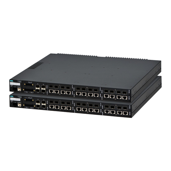
Introduction The RUGGEDCOM RST2228P is a utility grade, fully managed, industrial Ethernet switch designed to operate reliably in harsh environments. With a rugged metal enclosure and an optional conformal coating, the RUGGEDCOM RST2228P provides a high level of immunity to electromagnetic interference and heavy electrical surges, and can withstand temperatures between -40 and 85 °C (-40 and 185 °F). -
Page 11: Description
Reliability in Harsh Environments • Immunity to EMI and heavy electrical surges • Zero-Packet-Loss Technology • Supports Siemens FastConnect RJ45 Cabling System • -40 to 85 °C (-40 to 185 °F) operating temperature (fan-less) • Conformal coated printed circuit boards (optional) Description The RUGGEDCOM RST2228P features various ports, controls and indicator LEDs for connecting, configuring and troubleshooting the device. - Page 12 Introduction 1.2 Description • Option 1 Status panel, alarm LED, ACO Button, CLP port and USB console port are located on the front panel. Status Panel ACO Button CLP Port USB Console Port PoE Power and Failsafe Alarm Relay Terminal Block Power Terminal Block SFP/SFP+ Transceiver Sockets Media Modules...
- Page 13 Introduction 1.2 Description • Option 2 Status panel, alarm LED, ACO Button, CLP port and USB console port are located on the rear panel. Status Panel ACO Button CLP Port USB Console Port PoE Power and Failsafe Alarm Relay Terminal Block Power Terminal Block SFP/SFP+ Transceiver Sockets Media Modules...
- Page 14 Introduction 1.2 Description LEDs for 10GBase SFP+ Transceivers (Slot 0) Module Slot Locators LEDs for Module Ports Alarm Status LED Power Supply Status LEDs PoE Status LED ACO Button Figure 1.3 Status Panel State Description P{number} Solid Link detected (Green) Solid Link detected and PoE established (Yellow) Blinking Link activity...
-
Page 15: Required Tools And Materials
Introduction 1.3 Required Tools and Materials • "Connecting the Failsafe Alarm Relay (Page 14)" • "Failsafe Alarm Relay Specifications (Page 39)" • "Connecting External PoE Power (Page 21)" Power Supply Terminal Block A pluggable terminal block. For more information, refer to: •... -
Page 16: Cabling Recommendations
Siemens also does not recommend using copper Ethernet ports to interface with devices in the field across distances that could produce high levels of ground potential rise (i.e. greater than 2500 V), during line-to-ground fault conditions. -
Page 17: Supported Fiber Optic Cables
Introduction 1.5.3 Supported Fiber Optic Cables • Data cable lengths should be as short as possible, preferably 3 m (10 ft) in length. Copper data cables should not be used for inter-building communications. • Power and data cables should not be run in parallel for long distances, and should be installed in separate conduits. -
Page 18: Installing The Device
This product contains no user-serviceable parts. Attempted service by unauthorized personnel shall render all warranties null and void. Changes or modifications not expressly approved by Siemens AG could invalidate specifications, test results, and agency approvals, and void the user's authority to operate the equipment. -
Page 19: General Procedure
Installing the Device 2.1 General Procedure NOTICE This product should be installed in a restricted access location where access can only be gained by authorized personnel who have been informed of the restrictions and any precautions that must be taken. Access must only be possible through the use of a tool, lock and key, or other means of security, and controlled by the authority responsible for the location. -
Page 20: Unpacking The Device
Visually inspect each item in the package for any physical damage. Verify all items are included. Note If any item is missing or damaged, contact Siemens for assistance. Mounting the Device The RUGGEDCOM RST2228P is designed for maximum mounting and display flexibility. -
Page 21: Mounting The Device To A Panel
Installing the Device 2.3.2 Mounting the Device to a Panel To secure the device to a rack, do the following: Secure the mounting adapters to both sides of the chassis. Mounting Adapter Screw Figure 2.1 Installing the Mounting Adapters Insert the device into the rack. To make the modules and ports accessible from the front, insert the power supply side of the device first. - Page 22 Installing the Device 2.3.2 Mounting the Device to a Panel To mount the device to a panel, do the following: Secure the mounting adapters to both sides of the chassis. Mounting Adapter Screw Figure 2.2 Installing the Mounting Adapters Place the device against the panel and align the adapters with the mounting holes.
-
Page 23: Connecting The Failsafe Alarm Relay
Installing the Device 2.4 Connecting the Failsafe Alarm Relay Connecting the Failsafe Alarm Relay The failsafe relay can be configured to latch based on alarm conditions. The NO (Normally Open) contact is closed when the unit is powered and there are no active alarms. -
Page 24: Connecting Power
Installing the Device 2.5 Connecting Power Connect a failsafe device to the terminal block. Pluggable Terminal Block Screw-Type Terminal Block Normally Open Terminal Common Terminal Normally Closed Terminal Figure 2.5 Failsafe Alarm Relay Wiring Connecting Power The RUGGEDCOM RST2228P supports dual redundant AC and/or DC power supplies that can be installed in any combination. -
Page 25: Connecting High Ac/Dc Power
Installing the Device 2.5.1 Connecting High AC/DC Power NOTICE Do not disconnect protective Earth connections while the device is energized. NOTICE Before connecting power • A minimum wire gage is required for each power supply type. For more information, refer to "Power Supply Specifications (Page 37)". - Page 26 Installing the Device 2.5.1 Connecting High AC/DC Power Connect the power supply terminal block to the device. Pluggable Terminal Block Screw-Type Terminal Block Figure 2.6 Assembling the Power Supply Terminal Block Connect the Line wire from the power source to the positive/live (+/L) terminal on the terminal block.
-
Page 27: Connecting Low Dc Power
Installing the Device 2.5.2 Connecting Low DC Power For screw-type terminal blocks, install the safety cover. Figure 2.8 Assembling the Safety Cover Connect the chassis ground screw to ground (Potential Earth). It is recommended to terminate the ground connection with an M3 ring or spade lug, and then torque to 1.7 N·m (15 lbf-in). - Page 28 Installing the Device 2.5.2 Connecting Low DC Power NOTICE Electrical hazard – risk of damage to equipment. Do not connect AC power cables to a 12, 24 or 48 VDC power supply terminal block. Damage to the power supply may occur. NOTICE Electrical hazard –...
- Page 29 Installing the Device 2.5.2 Connecting Low DC Power Connect the positive wire from the power source to the positive terminal on the terminal block. Pluggable Terminal Block Screw-Type Terminal Block Positive (+) Terminal for PS1 Chassis/Ground Terminal for PS1 Negative (-) Terminal for PS1 Positive (+) Terminal for PS2 Chassis/Ground Terminal for PS2 Negative (-) Terminal for PS2...
-
Page 30: Connecting External Poe Power
For IEC 61850 compliance, use an IEC 61850 compliant PoE power supply with power cabling no longer than 3 m (118 in). Otherwise, Siemens recommends using the RUGGEDCOM RPS1300 switch-mode AC power supply. For more information about this power supply, refer to https:// support.industry.siemens.com/cs/ww/en/view/109478699. -
Page 31: Wiring Examples
Installing the Device 2.5.4 Wiring Examples To support the IEEE 802.3af specification (15 W/port output), the external power supply must meet the following requirements: Power Input Range Isolation Minimum Supply Type Power Required Minimum Maximum 45 VDC 57 VDC 1.5 kVAC/2.2 kVDC 72 W Based on a single 4-port module. - Page 32 Installing the Device 2.5.4 Wiring Examples Figure 2.15 Single High AC/DC Power Supply Figure 2.16 Single Low DC Power Supply RUGGEDCOM RST2228P Installation Manual, 07/2021, C79000-G8976-1403-13...
- Page 33 Installing the Device 2.5.4 Wiring Examples Figure 2.17 Dual High AC/DC Power Supply Figure 2.18 Dual Low DC Power Supply RUGGEDCOM RST2228P Installation Manual, 07/2021, C79000-G8976-1403-13...
- Page 34 Installing the Device 2.5.4 Wiring Examples Figure 2.19 High AC/DC Power Supply and Low DC Power Supply Figure 2.20 PoE Power Supply RUGGEDCOM RST2228P Installation Manual, 07/2021, C79000-G8976-1403-13...
- Page 35 Installing the Device 2.5.4 Wiring Examples RUGGEDCOM RST2228P Installation Manual, 07/2021, C79000-G8976-1403-13...
-
Page 36: Device Management
It may cause damage to the contact pins of the RJ45 ports. For a permanent solution, use Siemens 6XV1870-3Qxxx certified cables (manufactured December 2019 or after) or equivalent. Siemens recommends using Siemens certified cables and connectors for Siemens RUGGEDCOM products. -
Page 37: Configuring The Device
Device Management 3.2 Configuring the Device USB Console Port Connect a workstation directly to the USB Type-B console port to access the boot- time control and RUGGEDCOM RST2228P interfaces. The console port provides access to RUGGEDCOM RST2228P's console and Web interfaces. NOTICE Electrical Hazard –... -
Page 38: Inserting/Removing The Clp
Device Management 3.3 Inserting/Removing the CLP For more information about configuring the device, refer to the RUGGEDCOM ROS Configuration Manual associated with the installed software release. Inserting/Removing the CLP The RUGGEDCOM RST2228P accepts a CLP for storing configuration files and/or software updates. A protective cover is provided to prevent the ingress of dust and dirt when the CLP is not in use. - Page 39 Device Management 3.3 Inserting/Removing the CLP Insert a flat head screwdriver into the bottom portion of the CLP port, and gently pry the CLP out. Protective cover Figure 3.1 Removing the CLP Insert the protective cover or a new CLP to prevent the ingress of dust and dirt. RUGGEDCOM RST2228P Installation Manual, 07/2021, C79000-G8976-1403-13...
- Page 40 Device Management 3.3 Inserting/Removing the CLP Installing the CLP To install the CLP, do the following: Remove the protective cover from the CLP port. Protective cover Figure 3.2 Installing the CLP Insert the CLP into the CLP port. RUGGEDCOM RST2228P Installation Manual, 07/2021, C79000-G8976-1403-13...
- Page 41 Device Management 3.3 Inserting/Removing the CLP RUGGEDCOM RST2228P Installation Manual, 07/2021, C79000-G8976-1403-13...
-
Page 42: Communication Ports
4 x SFP/SFP+ Transceivers 1 to 6 Field-replaceable modules SFP Transceivers The RUGGEDCOM RST2228P supports up to four Small Form-factor Pluggable (SFP) transceiver sockets, which are compatible with the wide array of SFP/SFP+ transceivers available from Siemens. RUGGEDCOM RST2228P Installation Manual, 07/2021, C79000-G8976-1403-13... -
Page 43: Poe Ports
RUGGEDCOM SFP Transceiver Catalog [https:// support.industry.siemens.com/cs/ca/en/view/109482309]. Note Only use SFP transceivers approved by Siemens for RUGGEDCOM products. Siemens accepts no liability as a result of performance issues related in whole or in part to third-party components. PoE Ports The RUGGEDCOM RST2228P supports up to twenty-four 10/100/1000 Mbps Power over Ethernet (PoE) ports powered by an external power supply. -
Page 44: Available Modules
Available Modules A variety of modules are available for use with the RUGGEDCOM RST2228P. For more information, refer to the RUGGEDCOM Modules Catalog [https:// support.industry.siemens.com/cs/us/en/view/109752858] for the RUGGEDCOM RST2228P. Installing/Removing Modules Upon installing a new media module in the device, all features associated with the module are available in RUGGEDCOM ROS. - Page 45 Communication Ports 4.4 Installing/Removing Modules Pull the module from the chassis to disconnect it. Figure 4.2 Removing a Module Install a new module or a blank module (to prevent the ingress of dust and dirt). [Optional] If necessary, install the device in the rack. Connect power to the device.
-
Page 46: Technical Specifications
Technical Specifications This section provides important technical specifications related to the device. General Specifications Insulation Class I Overvoltage Category OVC II Power Supply Specifications Note When determining cable lengths, make sure the nominal input voltage for the power supply is provided at the input power terminal. Note Use the internal fuse rating to determine the size of the external circuit breaker/fuse. -
Page 47: Poe Power Supply Specifications
Technical Specifications 5.3 PoE Power Supply Specifications Power Supply Voltage Rating Ampere Fuse Type Fuse Delay Rating % of Ampere Opening Time Rating 200% 5 seconds (maximum) 24 VDC 125 VAC/VDC 10 A Very Fast Acting 100% 4 hours (minimum) 200% 5 seconds (maximum) 48 VDC... -
Page 48: Failsafe Alarm Relay Specifications
Technical Specifications 5.4 Failsafe Alarm Relay Specifications Power In Power Out Wire Gage Voltage Range Internal Fuse Rating 45-57 VDC 44-57 VDC, 15 W per Port Maximum (IEEE 802.af) The required wire size depends on the number of POE modules installed in the system and the maximum current capability of the POE power source. -
Page 49: Mechanical Specifications
Technical Specifications 5.7 Mechanical Specifications Ambient Operating -40 to 85 °C (-40 to 185 °F) Temperature Ambient Storage Temperature -40 to 85 °C (-40 to 185 °F) Ambient Relative Humidity 5% to 95% Pollution Degree Maximum Altitude 3000 m (9842 ft) Measured from a 30 cm (11.8 in) radius surrounding the center of the enclosure. - Page 50 Technical Specifications 5.8 Dimension Drawings 446.0 Figure 5.1 Overall Dimensions RUGGEDCOM RST2228P Installation Manual, 07/2021, C79000-G8976-1403-13...
- Page 51 Technical Specifications 5.8 Dimension Drawings 462.2 43.6 23.5 Figure 5.2 Rack Mount Dimensions 43.6 462.2 23.5 Figure 5.3 Panel Mount Dimensions RUGGEDCOM RST2228P Installation Manual, 07/2021, C79000-G8976-1403-13...
-
Page 52: Certification
The device is marked with a CSA symbol that indicates compliance with both Canadian and U.S. requirements. 6.1.2 European Union (EU) This device is declared by Siemens AG to comply with essential requirements and other relevant provisions of the following EU directives: EN 62368-1 •... -
Page 53: Tüv Süd
Products with Respect to the Restriction of Hazardous Substances The device is marked with a CE marking and can be used throughout the European community. A copy of the CE Declaration of Conformity is available from Siemens AG. For contact information, refer to "Contacting Siemens (Page vii)". -
Page 54: Fcc
Changes or modifications not expressly approved by the party responsible for compliance could void the user's authority to operate this device. 6.1.6 ISED This device is declared by Siemens AG to meet the requirements of the following ISED (Innovation Science and Economic Development Canada) standard: • CAN ICES-3 (A)/NMB-3 (A) 6.1.7... -
Page 55: Other Approvals
Certification 6.1.9 Other Approvals A copy of the Material Declaration is available online at https:// support.industry.siemens.com/cs/ww/en/view/109738831. 6.1.9 Other Approvals This device meets the requirements of the following additional standards: IEC 61850-3 • General Requirements • EN 50121-4 Railway Applications – Electromagnetic Compatibility – Emission and Immunity of the Signaling and Telecommunications Apparatus •... - Page 56 Certification 6.2 EMC and Environmental Type Tests Test Description Test Levels Severity Levels IEC 61000-4-4 Burst (Fast Signal Ports ± 4 kV at 2.5 Note Transient) and 5 kHz DC Power Ports ± 4 kV at 2.5 and 5 kHz AC Power Ports ±...
- Page 57 DC Power Ports 5 kV AC Power Ports 5 kV POE Power Ports 1 kV Siemens-specified severity levels EMC Immunity Type Tests per IEEE 1613 Description Test Levels Severity Levels Enclosure Contact ± 8 kV Enclosure Air ±...
- Page 58 Certification 6.2 EMC and Environmental Type Tests Environmental Type Tests Test Description Test Levels Severity Levels IEC 60068-2-1 Cold Temperature Test Ad -40 °C (-40 °F), 16 Hours IEC 60068-2-2 Dry Heat Test Bd 85 °C (185 °F), 16 Hours IEC 60068-2-14 Change of Test Nb...
- Page 59 Certification 6.2 EMC and Environmental Type Tests RUGGEDCOM RST2228P Installation Manual, 07/2021, C79000-G8976-1403-13...
- Page 60 Further Information Siemens RUGGEDCOM https://www.siemens.com/ruggedcom Industry Online Support (service and support) https://support.industry.siemens.com Industry Mall https://mall.industry.siemens.com Siemens AG Digital Industry Process Automation Postfach 48 48 90026 NÜRNBERG GERMANY...