Table of Contents
Advertisement
Quick Links
Advertisement
Table of Contents

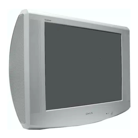
Summary of Contents for Sony TRINITRON AE-6B
- Page 1 AE-6B (KV-32LS65AUS) CHASSIS OPERATION MANUAL...
-
Page 2: Table Of Contents
TABLE OF CONTENTS Chapter 3. Video Processing Circuit Chapter 1. AE -6B Chassis Concept 3.1 VSP9407 Features 1.1 Features 3.2 Features of CRT Driver (CXA2100) 1.2 Specifications 1.3 21 Pin Connector Chapter 4. Micro Controller 1.4 Board Overview 4.1 Features of SAA5667 Micro Controller Chapter 2. -
Page 3: Chapter 1 Ae-6B Chassis Concept
Chapter 1 AE-6B Chassis Concept 1.1 Features BBE High Definition Sound system enhances clarity, detail and presence of sound for better intelligibility and musical realism. This is a new Chassis but some circuits are referred from other chassis. The Deflection Circuit and the Back End (CXA2100) are AE-6B chassis has Menu that is similar to FE-2 chassis. -
Page 4: Specifications
1.2 Specifications Picture Audio Terminals Right and left speaker REAR 100 Hz Digital Plus Digital Noise Reduction (DNR) 2X20W (Music Power) 1: 21-pin Euro Connector Inputs for audio and video signals. 2X10W (RMS) (CENELEC Standard) Inputs for YUV Outputs of TV video and audio signals. Others 2: 21-pin Euro Connector Inputs for audio and video signals. -
Page 5: Pin Connector
1.3 21 Pin Connector Figure 1.1 21-pin Euro connector... -
Page 6: Board Overview
1.4 Board Overview Figure 1.2 Board Overview (KV-32LS65AUS) -
Page 7: Chapter 2 Power Supply Circuit
Chapter 2 Power Supply Circuit 2.1 Power Supply Block Overview The primary power supply on the AE-6B chassis G board consists of three parts: 1. Oscillator 2. Output stage 3. Regulator Stage The oscillator starts up to produce an initial signal for the output stage. The output stage develops voltage to continue running the oscillator stage, supply the regulating stage and provide normal output for the TV. - Page 8 Driver / Output Stage IC6001 Normal Operation At start up, IC6001 initially uses current limit +B from pin 18 to power The oscillator voltage output at pins 12 and 16 use drivers Q6006 and internal drivers. These internal drivers amplify the oscillator signal and Q6007 to develop T6002 secondary voltages.
- Page 9 Figure 2.2 Main power supply circuit diagram.
- Page 10 Figure 2.3 Main power supply circuit diagram.
- Page 11 Figure 2.4 IC6001 block diagram.
-
Page 12: Overvoltage Protection
2.3 Overvoltage Protection 2.5 Protection Circuit of Power Block With the voltage divider R6038, R6039 and R6040 the +B voltage is • In case of OVP or OCP, the information goes to the A board via controlled. In case of failure, the zener diode D6009 is switched and a CN6006 and then direct via CN0001 to the micro controller on the M "high"... - Page 13 igure 2.5 Overvoltage Protection...
- Page 14 Figure 2.6 Overcurrent Protection...
-
Page 15: Chapter 3 Video Processing Circuit
Chapter 3 Video Processing Circuit... -
Page 16: Vsp9407 Features
3.1 VSP9407 Features • Integrated Video Matrix switch • Scan-rate-conversion: – Up to 7 CVBS inputs and up to 2 Y/C inputs – Motion adaptive frame based 100/120Hz interlaced scan – Up to three CVBS outputs (even Y/C input) conversion. •... - Page 17 Figure 3.2 VSP 9407 Block Diagram...
- Page 18 VSP 9407B Figure 3.3 VSP9407 Pinning...
-
Page 19: Features Of Crt Driver (Cxa2100)
3.2 Features of CRT Driver (CXA 2100) • Two sets of switchable YCbCr input • CbCr input offset adjustment circuit • LTI and CTI circuits • AKB system • Two sets of analog RGB inputs • Horizontal sync processing that supports 31.5kHz •... - Page 20 Figure 3.5 CXA 2100 Block Diagram...
-
Page 21: Chapter 4 Micro Controller
Chapter 4 Micro Controller 4.1 Features of SAA5667 Micro Controller SAA5667 single-chip microcontroller based 80C51 microcontroller, which is integrated with On-Screen Display (OSD) and Data Capture and display function for Teletext. It has 32 I/O ports via individual addressable controls, which are 5 V tolerant digital inputs and I/O. -
Page 22: Chapter 5 Audio Circuit
Chapter 5 Audio Circuit Figure 5.1 Audio block diagram for AE-6B chassis... - Page 23 Figure 5.2 MSP3411G block diagram...
-
Page 24: Features Of Msp3411G-B9
5.1 Features of MSP3411G-B9 MSP3411G-B9 is a multistandard sound processor. It enables Virtual Dolby Surround and BBE Digital Sound. It has 4 to 2 stereo matrix switching facilities. Besides, it has tone and balance controls as well as Automatic Volume Correction for loudspeaker channel. Figure 5.2 shows the block diagram of MSP3411G. - Page 25 Figure 5.4 TDA7497 block diagram...
-
Page 26: Chapter 6 Deflection Circuit
Chapter 6 Deflection Circuit... -
Page 31: Deflection Block Ae-6B (Protection)
6.1 Deflection Block AE-6B (Protections) - Page 32 Sony Corporation English 9-872-334-01 Sony Technology Malaysia Sdn. Bhd. © 2002.08 Visual Product...


