Table of Contents
Advertisement
Advertisement
Table of Contents

Related Manuals for Toro Lynx SmartHub


Summary of Contents for Toro Lynx SmartHub
- Page 1 Lynx SmartHub for LSM & GAC ® Installation and User Guide (DEC and DAC Series)
-
Page 2: Table Of Contents
Lynx® SmartHub Installation and User Guide Overview: Lynx Radio Repeater Toro’s Commitment to Excellence Operation Modes of Operation Introduction General Editing Timing Mechanism Components Cabinet Installation Power-Up Diagnostics Wallmount Home Button Earth Ground Start Button Power Source Pause Button Pedestal Installation... -
Page 3: Toro's Commitment To Excellence
Toro is committed to developing and producing the highest quality, best performing, most dependable products on the market. Because your satisfaction is our first priority, we have provided the Toro Helpline to assist you with any questions or problems that may arise. If for some reason you are not satisfied with your purchase or have questions, please contact us toll free at 1-877-345-8676. -
Page 4: Cabinet Installation
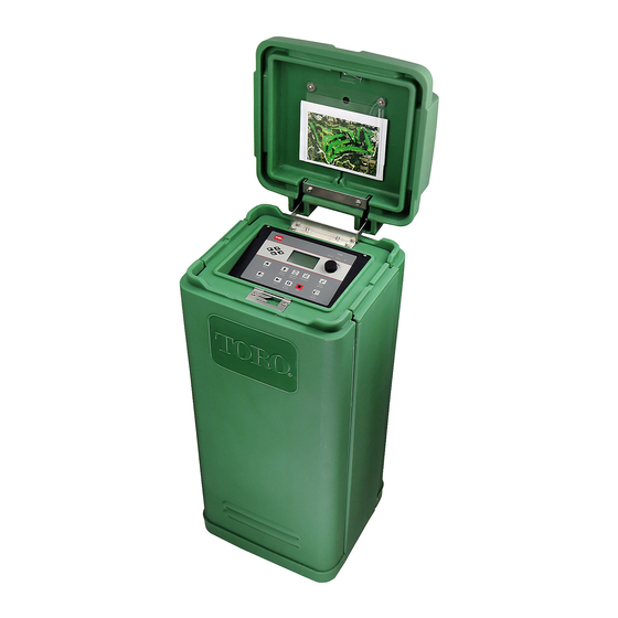
SmartHub is essential to safe and reliable operation. The Figure 1 SmartHub features a weather resistant cabinet designed for indoor or outdoor installation. Install the Lynx SmartHub: • on a vertical wall or other sturdy structure • so that the display is at or below eye level •... -
Page 5: Earth Ground
Lynx® SmartHub Installation and User Guide Power Source WARNING! AC POWER WIRING MUST BE INSTALLED AND CONNECTED BY QUALIFIED PERSONNEL ONLY. ALL ELECTRICAL COMPONENTS AND INSTALLATION PROCEDURES MUST COMPLY WITH ALL APPLICABLE LOCAL AND NATIONAL ELECTRICAL CODES. SOME CODES MAY REQUIRE A MEANS OF DISCONNECTION FROM THE AC POWER SOURCE, INSTALLED IN THE FIXED WIRING, HAVING A CONTACT SEPARATION OF AT LEAST 3mm IN THE LINE AND NEUTRAL POLES. -
Page 6: Pedestal Installation
Lynx® SmartHub Installation and User Guide Pedestal Installation Foundation Construction Figure 4 (Conduit Recommendations) 1. Prepare a hole for the foundation and Wood Form wiring conduit using the minimum recommended dimensions shown in Plastic Pedestal Base Area Figure 4. 3” (76mm) – Field Refer to local electrical codes for (32 Stations Each) required depth of buried wiring . -
Page 7: Earth Ground
Due to variables in soil manufacturer’s directions. composition and terrain, the method shown may not be suitable for your installation site. Contact your local Toro 4. Using a 5/8” (17mm) clamp or exothermic-weld fastener, distributor for assistance and availability of the required attach an 8 AWG (10mm²) solid copper wire near the top... - Page 8 Lynx® SmartHub Installation and User Guide Figure 6 No solenoid, power, or communication cables within this zone. pedestal or gateway 8’ (2.4m) 8’ (2.4m) 8’ (2.4m) 8’ (2.4m) 8’ (2.4m) grounding rod grounding plate concrete pad...
-
Page 9: Power Source
Lynx® SmartHub Installation and User Guide Power Source WARNING! AC POWER WIRING MUST BE INSTALLED AND CONNECTED BY QUALIFIED PERSONNEL ONLY. ALL ELECTRICAL COMPONENTS AND INSTALLATION PROCEDURES MUST COMPLY WITH ALL APPLICABLE LOCAL AND NATIONAL ELECTRICAL CODES. SOME CODES MAY REQUIRE A MEANS OF DISCONNECTION FROM THE AC POWER SOURCE, INSTALLED IN THE FIXED WIRING, HAVING A CONTACT SEPARATION OF AT LEAST 3mm IN THE LINE AND NEUTRAL POLES. -
Page 10: Lynx Smart Module (Lsm) Installation
Recommended Module-to-Solenoid cable: 14 AWG (2.1 mm2), solid copper, 2-conductor, direct burial. Burial Depth Toro recommends that the Controller-to-Module and Module-to-Solenoid cables should have a minimum cover of 6" (150mm). The irrigation plan may specify additional depth to be consistent with the depth of mainline or lateral pipe work and/or soil conditioning procedures such as aeration. - Page 11 DC Latching Solenoids. Out to additional modules The Lynx SmartHub output board can accommodate two cable paths with up to 250 stations each . Daughterboard LSM with hard-wired solenoid The maximum communication wire length between the module and the solenoid is 410' (125m).
-
Page 12: Gac Decoder Installation
GAC Decoder Installation New System or New Communication Cable AC station decoder modules are available in 1-station, 2-station, 4-station configuration or a Toro golf sprinkler with an integrated 1-station decoder. The SmartHub pedestal and cabinet can accommodate either two or four daughterboards. An expansion unit is required to install the 2nd daughterboard. - Page 13 Figure 9 Each station can activate up to 2 solenoids. (See valve compatibility for details.) 1-Station AC Solenoid Decoder Module Black Out to additional Station Wire decoder modules Black Valve Common Wire Each output circuit can accommodate up to Station 4 125 Decoder Modules.
-
Page 14: Existing System With Existing Wiring
The maximum resistance of the wire path with the end Valve Compatibility shorted can be 37.7 Ohms. The minimum resistance of the Toro Golf VIH (Solenoid 89-1905 or 118-0248) wire path with the end open should be 1000 Ohms. at 150 PSI... -
Page 15: Grounding The Communication Cable
5. Drive a 5/8” by 8’ (17mm x 2.5m) copper clad steel rod into well moistened soil not less than 8’ (2.5m) or not more The lightning arrester (Toro P/N DEC-SG-LINE) is required than 12’ (3.7m) from the controller cabinet (Figure 6). - Page 16 Lynx® SmartHub Installation and User Guide See Detail A Figure 10 For upgrades of existing systems, we recommend adding one ground point (Detail A) at the end of each main communication line. Maximum of 1000' (300 m) of populated communication line between ground points Golf Sprinkler with Decoder A = 500' (150m) Max...
-
Page 17: Motherboard Connections
3. Place the controller’s switch to ON. Master Valve / Pump Relay The Lynx SmartHub provides an output to control a master valve or pump relay. The output is active when any station is on, and off otherwise. Stations defined as switches do not cause the output to activate. -
Page 18: Communication Cable
Please note the following communication cable installation requirements and suggestions: • The remote SmartHub is designed for use with • If the communication cable is routed in the same shielded, twisted-pair, communication cable. Toro trench as main power wires, or the SmartHub to recommends R7162D or equivalent. -
Page 19: Communicating With The Smarthub
Lynx® SmartHub Installation and User Guide Communicating with the Lynx SmartHub A personal computer running Toro’s “Lynx” software is necessary to communicate with the Lynx SmartHub. The SmartHub allows Lynx software to control over 9,000 sprinkler heads with individual precision. -
Page 20: Layout 2 - Wired Lynx
SPU The Wireline connection is limited to about 9 miles. Layout 3 - Wireless The Lynx SmartHub DEC-RS-1000-DR (digital radio and modem) communicates with the Lynx computer via radio. The system is preconfigured at our production facility. Wireless GDC-200 –... -
Page 21: Radio Communication - Fiu To Smarthub
Lynx® SmartHub Installation and User Guide To Test Radio Communication Between the FIU and the Lynx SmartHub 1. Launch Lynx. See Figure 15. Figure 15 2. Click the Utilities bar (Figure 15, A). 3. Select the desired satelite from the list (Figure 15, B). -
Page 22: Changing The Frequency Of The Radio
14. Install radio back into FIU. 15. The UHF frequencies of the two radios involved (one in the FIU, one in the Lynx SmartHub) must match. Follow the above procedure with the radio from the Lynx SmartHub to specify a matching frequency. - Page 23 Lynx® SmartHub Installation and User Guide Figure 22 Figure 23 An FCC license is required to operate on any given UHF frequency. Frequency coordination (selection) is handled through the Personal Communications Industry Association (PCIA) (800-759-0300) and an application must be submitted to the FCC.
-
Page 24: Operation
General Editing Pressing a menu key on the Lynx SmartHub will display menu items. Items with fields containing values that can be edited are called Entry Fields. Use the Arrow Keys to navigate through the menus and entry fields. -
Page 25: Timing Mechanism Components
Lynx® SmartHub Installation and User Guide Timing Mechanism Components Left and Right Arrows allow you to select the next entry field within the same menu line. Any changes will be saved after you exit that entry field. Up and Down Arrows allow you to scroll up and down through the menu items. -
Page 26: Power-Up Diagnostics
Lynx® SmartHub Installation and User Guide Power-Up Diagnostics Upon power-up, the SmartHub will display: Gateway TM Booting The SmartHub TM will initiate a diagnostic test automatically during power-up. This function will take approximately ten seconds and it cannot be bypassed. If a problem is detected during the diagnostic test, it will be indicated on the display. The status information cannot be edited. -
Page 27: Start Button
Use the Stop function to cancel all irrigation (pictured), an active program, an individual station, a manual operation, or even a switch. If the Lynx SmartHub has no current activity, pressing the Stop button will have no effect. The Stop function causes a system cancel including power-down / power-up sequence for BOTH daughterboards regardless of station activity. -
Page 28: Smarthub Settings
Lynx® SmartHub Installation and User Guide SmartHub Settings Satellite Settings allows you to set SmartHub parameters such as Time, Date and Language. • Use the Up or Down Arrows to navigate through the menus. • Use the Left and Right Arrow to advance to the next entry field on the same menu line. -
Page 29: (Percent) Adjust
Lynx® SmartHub Installation and User Guide Clock Set: This setting sets the current time. Use the Left and Right Arrow Keys to select the Hours and Minutes parameters then use the Input Dial to modify the values. Clock Mode: Use this menu item to select the clock mode between Am/Pm (12-Hour) and 24-Hour mode. Date Mode: Use this menu item to select the date mode: MMDDYY or DDMMYY. -
Page 30: Station Settings
Lynx® SmartHub Installation and User Guide Station Settings Station Settings allows you to set parameters specific to each station as well as access the Sensor Setup Menu for setting up a Rain or Flow sensor. • Use the Up or Down Arrows to navigate through the menus. -
Page 31: Scheduled Watering
Lynx® SmartHub Installation and User Guide Hold Sta: Use this menu item to skip scheduled operations for this station or switch for a specified period of time. Select the hold duration from 01–30 days, Permanent or None. Holds do not affect manual operation. -
Page 32: Manual Watering
Lynx® SmartHub Installation and User Guide Station Based Flow Management: To review the SBF (Station Based Flow) Lists, access the SBF screen from the Scheduled Watering menu. Follow the steps to access. 1. Press the Scheduled Watering Key . The cursor is initially located at the program selection field. Use the Input Dial to select SBF List which is located between the first and last programs. - Page 33 Lynx® SmartHub Installation and User Guide M-Manual - Select M-Manual to activate a station or group of stations with a specified runtime. Multi-Manual Station Activation Directions Manual station activation example: Activate stations 1–12 with a runtime of 5 minutes each and limit watering to 3 stations simultaneously.
-
Page 34: Diagnostics
Lynx® SmartHub Installation and User Guide Diagnostics The Diagnostics function of the remote SmartHub allows for easy system troubleshooting. Within this function, the user can monitor the SmartHub’s internal voltages as well as check the firmware version. Use the Input Dial to navigate through the menus while in the Menu: field. - Page 35 Lynx® SmartHub Installation and User Guide Menu: DB Monitor Displays the voltage and amperage of the Menu: DB Monitor daughterboards attached to the motherboard, as well as the amps for L1 and L2 (black and Volts 38.8V None white respectively) terminals. Amps 0.000A 0.000A...
- Page 36 Lynx® SmartHub Installation and User Guide Menu: Radio Ping For this menu item to work, the radio needs an address. The radio address is generated from the Satellite address. The radio within the satellite and the target radio must be on the same frequency.
-
Page 37: Motherboard Diagnostic Display
Lynx® SmartHub Installation and User Guide Motherboard Diagnostic Display The SmartHub motherboard features a 2-line, 16 character LCD display (A) for quickly viewing for system diagnostic information. Use the - and + buttons (B) to scroll through the display lines and available options and the ENTER button to clear alarms when prompted. - Page 38 Lynx® SmartHub Installation and User Guide Alarm Conditions All of the Alarm Conditions, when active, toggle back and forth between the two message states below. Thermal Alarm • Shuts off and disables daughterboard indefinitely. D1 Thermal D2 A=0.500 • Motherboard LCD toggles alarm and instruction on how to re-enable the daughterboard.
-
Page 39: Specifications
GDC, CDS and Turf Guard), unless covered by a they are used for irrigation purposes under manufacturer’s Toro NSN Support Plan, are covered by this warranty for one recommended specifications. year from date of installation. - Page 40 Lynx® SmartHub Installation and User Guide Notes WARNING: Cancer and Reproductive harm – www.P65Warnings.ca.gov. For more information, please visit www.toro.com/CAProp65. Patent: www.ttcopats.com ©2020 The Toro Company, Irrigation Division • www.toro.com • 1-877-345-8676 Form Number 373-0965 Rev. C...