Bosch HGS8055UC Installation Manual
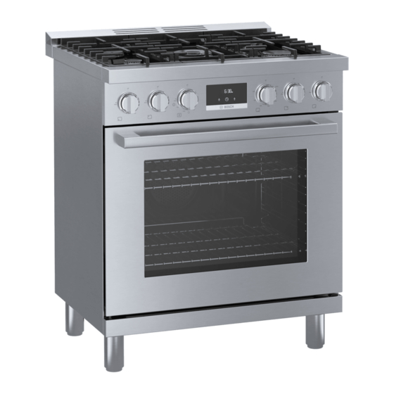
Free-standing range
Hide thumbs
Also See for HGS8055UC:
- Use and care manual (68 pages) ,
- Installation manual (48 pages) ,
- Installation manual (48 pages)

Related Manuals for Bosch HGS8055UC


Summary of Contents for Bosch HGS8055UC
- Page 1 Free-standing range Installation Manual HGS8055UC, HGS8045UC, HGS8655UC, HGS8645UC...
-
Page 3: Table Of Contents
Installation Instructions ö Technical Data ..............10 Safety Definitions ............. 3 Installation Checklist ............11 IMPORTANT SAFETY INSTRUCTIONS ......4 Appliance Handling Safety ..........5 Installation Procedure ..........11 Safety Codes and Standards ..........5 How to Remove the Oven Door ........11 Electric Safety ............... -
Page 4: Important Safety Instructions
IMPORTANT SAFETY INSTRUCTIONS READ AND SAVE THESE INSTRUCTIONS I M P O R T A N T S A F E T Y I N S T R U C T I O N S R E A D A N D S A V E T H E S E I N S T R U C T I O N S... -
Page 5: Appliance Handling Safety
IMPORTANT SAFETY INSTRUCTIONS READ AND SAVE THESE INSTRUCTIONS IMPORTANT: THE APPLIANCE MUST BE INSTALLED BY Appliance Handling Safety A QUALIFIED INSTALLER. Hidden surfaces may have sharp edges. INSTALLER: LEAVE THESE INSTRUCTIONS WITH THE Use caution when reaching behind or APPLIANCE AFTER INSTALLATION IS COMPLETE. under appliance. -
Page 6: Gas Safety
IMPORTANT SAFETY INSTRUCTIONS READ AND SAVE THESE INSTRUCTIONS The circuit breaker should have a contact separation of For Massachusetts installations: at least 3 mm on all poles. Installation must be performed by a qualified or ▯ Installer – show the owner the location of the circuit licensed contractor, plumber or gas fitter qualified or breaker or fuse. -
Page 7: Conversion To Propane Gas
IMPORTANT SAFETY INSTRUCTIONS READ AND SAVE THESE INSTRUCTIONS Conversion to Propane Gas WARNING Personal injury or death from electrical shock may occur if the appliance is not installed by a qualified installer or electrician. Any additions, changes or conversions required in order for this appliance to satisfactorily meet the application needs must be made by a qualified technician. -
Page 8: Before You Begin
Before You Begin B e f o r e Y o u B e g i n Tools and Parts Needed 36”: Phillips head screwdriver ▯ Slotted screwdriver 1/8" (3,5 mm) ▯ Adjustable wrench ▯ Tongue and groove pliers ▯ Socket or flat wrench 3/8”... -
Page 9: General Information
General Information Cabinet Requirements 30”: X = Grounded Outlet Y = Gas Supply Line The minimum spaces that must be maintained when installing the gas cooktop shall be: 36”: minimum 18" (457 mm) minimum 30" (762 mm) clearance between the top of the cooking surface and the bottom of the unprotected wood or metal cabinet 30": minimum 30"... -
Page 10: Technical Data
Choose one of the following built-in configurations. Low Backguard Installation (applicable both with non combustible back wall and combustible back wall) Installation allowed only with non combustible back wall Option 1: A >= 12'' (305 mm) and B >= 28'' (711 mm) ▯... -
Page 11: Installation Checklist
Installation Checklist Installation step è Please refer to the pages following for complete Removing the oven door prior to installation installation instructions. Use this checklist to verify that reduces the unit weight and makes the range you have completed each step of the installation easier to move. -
Page 12: Fitting The Rear Vent Trim
Fitting the Rear Vent Trim Close the oven door until it catches on the hinge stop levers, locking the hinges at the correct angle for door The rear vent trim is nested in the styrofoam removal. The door can be removed when it is pulled packaging. -
Page 13: Connect Gas Supply
Screw the adjustable feet into the mounting holes on Check inlet fittings and regulator for leaks. the underside of the appliance. Note: If the appliance needs to be moved again, screw the adjustable feet in fully. Carefully move the appliance back on the feets. Turn the adjustable feet to align the appliance. -
Page 14: Install Appliance
Install Appliance Check supply line connections for leaks using a soap solution or non-corrosive leak detection fluid. Do not use a flame of any sort. WARNING TIP OVER HAZARD WARNING Install a gas shut off valve near the appliance. After installation, it must be easily accessible in an A child or adult can tip the emergency. - Page 15 Align the base of the hook of the bracket with the base Use the following distances for the distance from the on the slot of the rear wall fastening bracket. Align the side of the appliance to the bracket holes. base of the fastening bracket with the ground and tighten the screws to fix the measurements.
-
Page 16: Connect Electrical Supply
The burner parts must be correctly positioned for the WARNING cooktop to function properly. If the burner parts are not correctly positioned, one or more of the following The rear vent trim has 3/16” (5 mm) standoffs to problems may occur: keep the appliance slightly off of the back wall. -
Page 17: Check The Installation
Checking Burner Cap Placement Checking the flame characteristics Check to make sure that there is no gap between the Yellow flames: burner cap and burner base. See illustration below for Further adjustment is correct and incorrect placements of the burner cap. required. -
Page 18: Conversion To Propane Gas (Lpg)
Conversion to Propane Gas (LPG) Always provide adequate gas supply. 30” This appliance is shipped from the factory for use with natural gas. Use this kit to convert the appliance for propane gas use if necessary. Observe the following: Ensure that the range is converted for use with the appropriate gas before using it. - Page 19 Orifices Type of gas Pressure Burner Type Nozzle Bypass Min Power Max Power in W.C.P. Number Natural gas 5” Dual-flame burner external 180 (S4) 1000 BTU 18000 BTU (0.3 kW) (5.3 kW) Dual-flame burner internal Large burner 2400 BTU 10000 BTU (0.7 kW) (2.9 kW) Small burner...
- Page 20 Remove the nozzle D and replace it with an Setting the minimum gas flow appropriate nozzle for the new type of gas. Remove the control knob and knob ring. Standard-output burner/high-output burner Turn the inner setting screw clockwise gently until it bottoms out.
- Page 21 Unscrew the bake burner nozzle and replace it with the Replacing the Oven Burner Nozzle LP nozzle number 120. Open the appliance door. Remove the screws on the bake chamber cover and lift the front of the bake chamber cover slightly and then pull it out towards you.
- Page 22 Reinsert the broil burner & broil burner sub assembly Replacing the Broil Burner Nozzle and screw tight. Open the appliance door. Fill out the LP conversion label (included) and affix to Remove the screws on the broil burner sub assembly the appliance.
-
Page 23: Technical Service
800 944 2904 toll-free How to Obtain Warranty Service To obtain warranty service for your Product, you should contact Bosch Customer Service at 1-800-944-2904 to schedule a repair. Model (E) number and FD number When you contact our service, please have the Model (E) number and the FD number for your appliance available.