Table of Contents
Advertisement
Advertisement
Table of Contents

Related Manuals for D-Link DGS-2208


Summary of Contents for D-Link DGS-2208
-
Page 2: Table Of Contents
Mounting the Switch on the Wall... 17 Mounting on a cement wall ... 17 Mounting on a wood wall ... 17 Connecting the Switch ... 18 DGS-2208 to End Node... 18 Hub/Switch to DGS-2208... 18 Connecting To Network Backbone or Server ... 18 Troubleshooting... 19 Glossary ... -
Page 3: Safety Instructions
• Do not spill food or liquids on your system components, and never operate the product in a wet environment. If the system gets wet, see the appropriate section in your troubleshooting guide or contact your trained service provider. D-Link DGS-2208 User Manual Safety Instructions Safety Cautions... - Page 4 • To help avoid damaging your system, be sure the voltage selection switch (if provided) on the power supply is set to match the power available at your location: –...
- Page 5 – If the system has multiple sources of power, disconnect power from the system by unplugging all power cables from the power supplies. • Move products with care; ensure that all casters and/or stabilizers are firmly connected to the system. Avoid sudden stops and uneven surfaces. D-Link DGS-2208 User Manual...
-
Page 6: Protecting Against Electrostatic Discharge
2. When transporting a sensitive component, first place it in an antistatic container or packaging. 3. Handle all sensitive components in a static-safe area. If possible, use antistatic floor pads, workbench pads, and an antistatic grounding strap. D-Link DGS-2208 User Manual... -
Page 7: Product Overview
• Visually inspect the DC power jack and make sure that it is fully secured to the power adapter. • Do not cover the ventilation holes on the sides of the Switch, and make sure there is adequate ventilation around it. -
Page 8: Introduction
Gigabit Ethernet NIC’s are able to perform 10 times the number of operations in the same amount of time. In addition, the phenomenal bandwidth delivered by Gigabit Ethernet is the most cost-effective method to take advantage of today and tomorrow’s rapidly improving switching and routing internetworking technologies. D-Link DGS-2208 User Manual... - Page 9 For Ethernet networks, a switch is an effective way of eliminating the problem of chaining hubs beyond the “two-repeater limit.” A switch can be used to split parts of the network into different collision domains, making it possible to expand your Ethernet network beyond the 205-meter network diameter limit for 100BASE-TX networks.
- Page 10 Jumbo Frame Support The DGS-2208 switch supports Jumbo Frames up to (9K) in size. Jumbo Frame support is designed to improve network throughput and significantly reduce the CPU utilization of large file transfers such as multimedia files or large data files by enabling more efficient larger payloads per packet.
-
Page 11: Features
The DGS-2208 8-port 10/100/1000BASE-T Gigabit Ethernet Switch was designed for easy installation and high performance in an environment where traffic on the network and the number of users increase continuously. • Eight (8) 10/100/1000BASE-T Gigabit Ethernet ports • Cable Diagnostic function at Switch boot up •... -
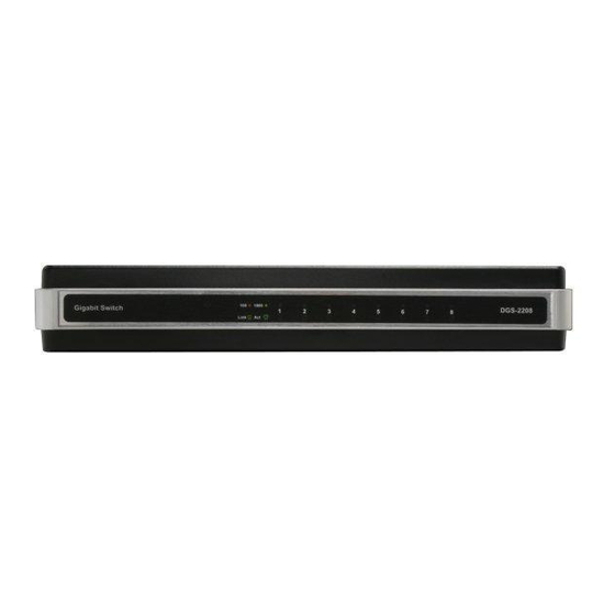
Page 12: Hardware Overview
LED indicators follows (see LED Indicators). The LED indicators of the Switch include Power, Link/Act, 1000Mbps, and 100Mbps. The Cable Diagnostic functions of the Switch are indicated by a combination of the Speed and the Link/Act LEDs, as described on the next page. - Page 13 Cable Diagnostic − LED Indications When the Switch is booted up (when the Switch is first powered on), the Cable Diagnostic function is initialized and run. The Cable Diagnostic function will detect three common faults in an Ethernet cable connecting the Switch to a...
- Page 14 10 seconds. If a cable fault is detected, it is indicated by the corresponding port’s Speed LED glowing amber for 5 seconds, after the initial port scan. The Switch is then reset for normal operation. It takes about 2 seconds for the Switch to reset.
-
Page 15: Rear Panel (Connections)
Power is supplied through an external AC power adapter. Check the technical specification section for information about the AC power input voltage. Since the DGS-2208 does not require a power button, plugging its power adapter into a power outlet will immediately power it on. -
Page 16: Installation
This section will explain how to connect Ethernet devices to your new D-Link switch and how to mount the switch. Before You Connect to the Network The site where you install the Switch may greatly affect its performance. Please follow these guidelines for setting up the Switch. -
Page 17: Mounting The Switch On The Wall
Mounting the Switch on the Wall The DGS-2208 can also be mounted on a wall. Two mounting slots are provided on the bottom of the switch for this purpose. Please make sure that the front panel is exposed in order to view the LEDs. Please refer to the illustration below: 1. -
Page 18: Connecting The Switch
End nodes include PCs outfitted with a 10, 100, or 1000 Mbps RJ-45 Ethernet Network Interface Card (NIC) and most routers. An end node can be connected to the Switch via a twisted-pair Category 3, 4, 5, or 5e UTP/STP cable. The end node can be connected to any of the ports of the Switch. -
Page 19: Troubleshooting
Crossover) and adjust themselves accordingly to pass data over the network. 3. What is the maximum length of Category 3, 4 or 5 twisted pair cable that can be used between the DGS-2208 and other devices such as routers, switches, computers, etc.? The maximum length of Category 3, 4 or 5 twisted pair cable that can be used between computers and other devices on a network is 100 meters or about 328 feet. -
Page 20: Glossary
The IEEE 802.3 specification for Ethernet over Unshielded Twisted Pair (UTP) cabling. aging The automatic removal of dynamic entries from the Switch Database which have timed-out and are no longer valid. Asynchronous Transfer Mode. A connection oriented transmission protocol based on fixed length cells (packets). ATM is designed to carry a complete range of user traffic, including voice, data, and video signals. - Page 21 A port that does not learn device addresses, and that receives all frames with an unknown address. Backbone ports are normally used to connect the Switch to the backbone of your network. Note that backbone ports were formerly known as designated downlink ports.
- Page 22 The port on the Switch accepting a terminal or modem connector. It changes the parallel arrangement of data within computers to the serial form used on data transmission links. This port is most often used for dedicated local management.
- Page 23 The port in a resilient link that carries data traffic in normal operating conditions. Medium Dependent Interface. An Ethernet port connection where the transmitter of one device is connected to the receiver of another device. D-Link DGS-2208 User Manual...
- Page 24 Remote Monitoring. Subset of SNMP MIB II, which allows monitoring and management capabilities by addressing up to ten different groups of information. Redundant Power System. A device that provides a backup source of power when connected to the Switch. D-Link DGS-2208 User Manual...
- Page 25 A device that filters, forwards, and floods packets based on the packet’s destination address. The Switch learns the addresses associated with each switch port and builds tables based on this information to be used for the switching decision. TCP/IP A layered set of communications protocols providing Telnet terminal emulation, FTP file transfer, and other services...
- Page 26 Virtual LAN. A group of location- and topology-independent devices that communicate as if they are on a common physical LAN. Virtual LAN Trunk. A Switch-to-Switch link which carries traffic for all the VLANs on each Switch. VT100 A type of terminal which uses ASCII characters. VT100 screens have a text-based appearance.
-
Page 27: Networking Basics
Check your IP address After you install your new D-Link adapter, by default, the TCP/IP settings should be set to obtain an IP address from a DHCP server (i.e. wireless router) automatically. To verify your IP address, please follow the steps below. -
Page 28: Statically Assign An Ip Address
2000 - From the desktop, right-click My Network Places > Properties. ® Step 2 Right-click on the Local Area Connection which represents your D-Link network adapter and select Properties. Step 3 Highlight Internet Protocol (TCP/IP) and click Properties. Step 4 Click Use the following IP address and enter an IP address that is on the same subnet as your network or the LAN IP address on your router. -
Page 29: Technical Specifications
Address Aging Timer Max Power Consumption Linear AC-DC 7.5V/1A = 6.75W Jumbo Frames Interface Options RJ-45 Network Protocols and Standards D-Link DGS-2208 User Manual DGS-2208 Specifications Eight (8) Ports 10/100/1000Mbps 16Gbps Forwarding Capacity Store-and-forward Per Unit: Power Per Port: Activity/Link... - Page 30 Safety Agency Certifications and Environmental Safety Temperature Humidity Physical Specifications Dimensions D-Link DGS-2208 User Manual CE Mark, FCC Class B Linear AC-DC 7.5V/1A Switching AC-DC 5V/2A Operating: 0° - 40° C (32° - 131° F) Storage: -10° - 70° C (14° - 158° F) Operating: 10% to 90% RH, Non Condensing (W x D x H) 7.5 x 4.6 x 1.38 inches (190.5mm x 116.84mm x 35mm)
-
Page 31: Contacting Technical Support
Contacting Technical Support D-Link provides free technical support for customers within the United States and within Canada for the duration of the warranty period on this product. U.S. and Canadian customers can contact D-Link technical support through our web site or by phone. -
Page 32: Warranty
Any repair or replacement will be rendered by D-Link at an Authorized D-Link Service Office. The replacement hardware need not be new or have an identical make, model or part. D-Link may, at its option, replace the defective Hardware or any part thereof with any reconditioned product that D-Link reasonably determines is substantially equivalent (or superior) in all material respects to the defective Hardware. - Page 33 Warranty Period and is subject to the same limitations and exclusions. If a material non-conformance is incapable of correction, or if D-Link determines in its sole discretion that it is not practical to replace the non-conforming Software, the price paid by the original licensee for the non-conforming Software will be refunded by D-Link;...
- Page 34 • The customer is responsible for all in-bound shipping charges to D-Link. No Cash on Delivery (“COD”) is allowed. Products sent COD will either be rejected by D-Link or become the property of D-Link. Products shall be fully insured by the customer and shipped to D-Link Systems, Inc., 17595 Mt.
-
Page 35: Limitation Of Liability
This Limited Warranty provides specific legal rights and you may also have other rights which vary from state to state. Trademarks: D-Link is a registered trademark of D-Link Systems, Inc. Other trademarks or registered trademarks are the property of their respective owners. -
Page 36: Fcc Statement
• Connect the equipment into an outlet on a circuit different from that to which the receiver is connected. • Consult the dealer or an experienced radio/TV technician for help. For detailed warranty information applicable to products purchased outside the United States, please contact the corresponding local D-Link office. D-Link DGS-2208 User Manual... -
Page 37: Registration
Product registration is entirely voluntary and failure to complete or return this form will not diminish your warranty rights. D-Link DGS-2208 User Manual Registration Version 1.0 02/08/2006...