Advertisement
Quick Links
SERVICE MANUAL
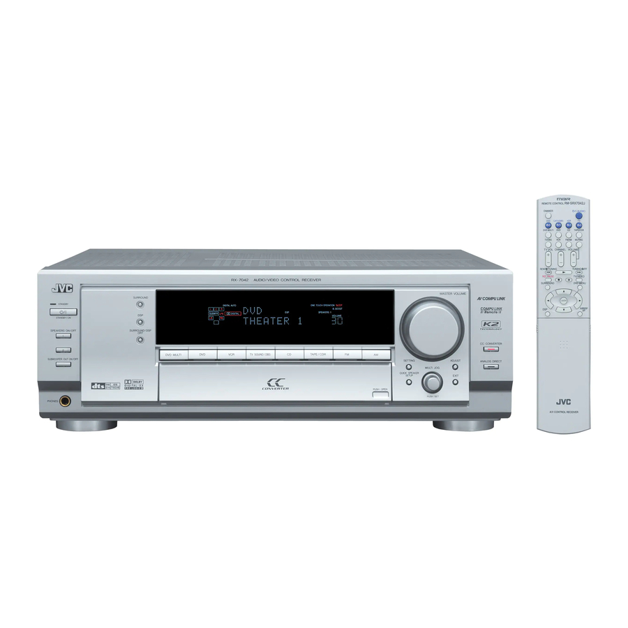
AUDIO/VIDEO CONTROL RECEIVER
3
2004
MB172
1
PRECAUTION. . . . . . . . . . . . . . . . . . . . . . . . . . . . . . . . . . . . . . . . . . . . . . . . . . . . . . . . . . . . . . . . . . . . . . . . . 1-3
2
SPECIFIC SERVICE INSTRUCTIONS . . . . . . . . . . . . . . . . . . . . . . . . . . . . . . . . . . . . . . . . . . . . . . . . . . . . . . 1-5
3
DISASSEMBLY . . . . . . . . . . . . . . . . . . . . . . . . . . . . . . . . . . . . . . . . . . . . . . . . . . . . . . . . . . . . . . . . . . . . . . . 1-6
4
ADJUSTMENT . . . . . . . . . . . . . . . . . . . . . . . . . . . . . . . . . . . . . . . . . . . . . . . . . . . . . . . . . . . . . . . . . . . . . . . 1-13
5
TROUBLESHOOTING . . . . . . . . . . . . . . . . . . . . . . . . . . . . . . . . . . . . . . . . . . . . . . . . . . . . . . . . . . . . . . . . . 1-14
RX-7042S
TABLE OF CONTENTS
COPYRIGHT © 2004 VICTOR COMPANY OF JAPAN, LIMITED
Area suffix
J ----------------------------- U.S.A.
C -------------------------- Canada
No.MB172
2004/3
Advertisement

Related Manuals for JVC RX-7042S


Summary of Contents for JVC RX-7042S
-
Page 1: Table Of Contents
SERVICE MANUAL AUDIO/VIDEO CONTROL RECEIVER MB172 2004 RX-7042S Area suffix J ----------------------------- U.S.A. C -------------------------- Canada TABLE OF CONTENTS PRECAUTION............... . . 1-3 SPECIFIC SERVICE INSTRUCTIONS . - Page 2 SPECIFICATION Amplifier Output Power Ω At Stereo Front ch 130 W per channel, min. RMS, driven into 8 , 20 Hz to 20 kHz, with no more than 0.08% total harmonic Operation distortion. Ω At Surround Front ch 130 W per channel, min. RMS, driven into 8 at 1 kHz, with no more than 0.8% total harmonic distortion.
-
Page 3: Precaution
SECTION 1 PRECAUTION Safety Precautions (1) This design of this product contains special hardware and voltmeter. many circuits and components specially for safety purpos- Move the resistor connection to each exposed metal es. For continued protection, no changes should be made part, particularly any exposed metal part having a return to the original design unless authorized in writing by the path to the chassis, and measure the AC voltage across... - Page 4 Importance administering point on the safety Power / fuse board 6.3A-125V Power trans 1 board Caution: For continued protection against risk of fire, replace only with same type 6.3A/125V for F1, 2A/125V for F61 and F62. This symbol specifies type of fast operating fuse. Precaution: Pour eviter risques de feux, remplacez le fusible de surete de F1 comme le meme type que 6.3A/125V, et 2A/125V pour F61 et F62.
-
Page 5: Specific Service Instructions
SECTION 2 SPECIFIC SERVICE INSTRUCTIONS This service manual does not describe SPECIFIC SERVICE INSTRUCTIONS. (No.MB172)1-5... -
Page 6: Disassembly
SECTION 3 DISASSEMBLY Removing the top cover (See Fig.1) (1) From the right and left sides of the main body, remove the four screws A attaching the top cover. Top cover (2) From the back side of the main body, remove the three screws B attaching the top cover. - Page 7 Removing the rear panel (See Fig.4) • Prior to performing the following procedures, remove the top Strain relief cover. (1) From the back side of the main body, remove the strain re- lief from the rear panel in the direction of the arrow. (2) Remove the twenty-nine screws E, two screws F and three screws G attaching the rear panel.
- Page 8 Removing the micon board (See Fig.7) • Prior to performing the following procedures, remove the top cover, rear panel, I/O board, tuner, DSP board, audio board, Main board video board and S-video board. CN831 (1) From the top side of the main body, disconnect the card on the micon board.
- Page 9 Removing the main board (See Fig.9) • Prior to performing the following procedures, remove the top Front board(R) Front board(L) cover. Surround board Center board (1) From the top side of the main body, remove the tie bands CN881 Tie band bundling the wires.
- Page 10 3.10 Removing the center board, surround back board, front boards (L/R) and surround boards (L/R) (See Figs.10 and 12) • Prior to performing the following procedures, remove the top Front board(R) Front board(L) cover and main board. (1) From the reverse side of the main board, remove the two screws P attaching the main board to the heat sink.
- Page 11 3.13 Removing the power supply board Power supply board (See Fig.14) CN402 Card wire Headphone • Prior to performing the following procedures, remove the top jack board cover. (1) From the top side of the main body, disconnect the parallel wires from the connector CN55 on the power transformer...
- Page 12 3.17 Removing the front key & system control board (See Figs.17 to 20) • Prior to performing the following procedures, remove the top Front panel assembly cover, front panel assembly, switch board and power switch Volume knob board. (1) Pull out the volume and jog knobs from the front side of the front panel assembly, remove the nut attaching the front key &...
-
Page 13: Adjustment
SECTION 4 ADJUSTMENT Adjustment method Tuner section 1. Tuner range 87.5MHz to 108.0MHz 530kHz to 1710kHz Power amplifier section Adjustment of idling current Measurement location B2204-82205 (Lch), B2213-B2214 (Rch) Adjustment part VR787 (Lch), VR788 (Rch) Attention: This adjustment does not obtain a correct adjustment value immediately after the amplifier is used (state that an in- ternal temperature has risen). -
Page 14: Troubleshooting
SECTION 5 TROUBLESHOOTING Self-diagnose function This model incorporates the following self-diagnostic functions. 1. PROTECTOR • The PROTECTOR IN port detects errors such as speaker overcurrent and DC voltage output errors (Active: L). Immediately after detection, all relays are switched off and the alarm display as shown below (blinking at intervals of 0.5 sec. ON and 0.5 sec. OFF) is displayed in the lower part of the FL matrix. - Page 15 (No.MB172)1-15...
- Page 16 VICTOR COMPANY OF JAPAN, LIMITED AV & MULTIMEDIA COMPANY AUDIO/VIDEO SYSTEMS CATEGORY 10-1,1chome,Ohwatari-machi,Maebashi-city,371-8543,Japan (No.MB172) Printed in Japan...
- Page 17 SCHEMATIC DIAGRAMS AUDIO/VIDEO CONTROL RECEIVER RX-7042S CD-ROM No.SML200403 Area suffix J ----------------------------- U.S.A. C -------------------------- Canada Contents Block diagram Standard schematic diagrams 2-23 to 33 Printed circuit boards No.MB172SCH COPYRIGHT 2004 VICTOR COMPANY OF JAPAN, LTD. 2004/3...
- Page 18 In regard with component parts appearing on the silk-screen printed side (parts side) of the PWB diagrams, the parts that are printed over with black such as the resistor ( ), diode ( ) and ICP ( ) or identified by the " " mark nearby are critical for safety.
- Page 19 < M E M O >...
- Page 20 Block diagram Audio signal input section System control section DSPCLK, DSPREADY, DSPRESET DSPSTATUS, DSP_COMMAND MAIN_STB, MAIN_CLK HP_RELAY MAIN_DATA, TUCE TUCE, TUCK, TUDI, TUDO SUR_RELAY, C_RELAY, SUB_RELAY TUDI, TUDO, TUCK IC901 F1_RELAY, F2_RELAY, SBK_RELAY TUNER MAIN_STB SW_MUTE System MAIN_CLK VIDEO1, VIDEO2, VIDEO3, VIDEO4 FR_RELAY, C_RELAY MAIN_DATA VOL_STB, VOL_CLK, VOL_DATA...
- Page 21 DSP IC / Digital signal input terminal section IC671 DSPRESET, DSPREADY, DSPCOMMAND Q2101, Q2102, Q2201, Q2202 MICK DSP_STATUS, DSP_CLK Digital Signal S.MUTE Q2301, Q3401, Q2501, Q2708 Controller S.MUTE DSP.L A4+/- IC611 to IC613 DSP.R B3+/- PD_DD, RST_DD AMP. IC682 IC673 96K/48K, 192K/96K AD/DA J681...
- Page 22 Standard schematic diagrams Primary section CN811 QGA3901F2-03 (SHEET 2) CN55 QGD2501C1-05Z CN402 QGF1205C1-06 FW51 QUM215-10DGZ4 0.047MY 0.047MY 10DDA20-FD 11ES2-T4 0.0047/100 0.1MY 0.1MY 100k 0.1MY 10DDA20-FD CN71 CN82 QGB2510K1-08 QGB2510J1-09 11ES2-T4 1000/35 3300/35 1000/2 11ES2-T4 220/50 KTA1046/Y/ TH71 QAD0095-4R7Z 11ES2-T4 11ES2-T4 MTZ8.2JC MTZ36JC 22/50...
- Page 23 PW10 PW20 PW11 PW17 PW12 PW13 PW14 PW15 PW16 PW26 PW18 PW28 PW19 PW29 PW30 PW40 3.3M 0.0047/100 KRC105M QSK0098-001 1SS133 KTD863/Y/ 1000/25 470/16 EP51 Parts are safety assurance parts. When replacing those parts make sure to use the specified one. SHEET 1...
- Page 24 Speaker terminal section (SHEET 4) (SHEET 4) (SHEET 3) (SHEET 3) (SHEET 4) (SHEET 7 CN702 CN704 CN701 CN705 QGB2510J1-10 QGB2510J1-12 QGB2510J1-12 QGB2510J1-12 CN703 QGB2510J1-10 C816 100/25 D816 MTZ18JC C803 C801 0.01 R816 3.3k D801 30PRA20-FC D803 30PRA20-FC C804 C802 0.01 D802 30PRA20-FC...
- Page 25 (SHEET 7) (SHEET 7) R833 R831 C835 0.022 C834 CN706 0.022 QGB2510J1-12 ST832 D831 RY831 QNB0082-002 1SS133 QSK0109-001 220p C846 C847 220p R832 C839 0.022 CN813 QGA3901C1-06 L843 0.45 B6001 ST833 CN814 L844 0.45 QGA3901C1-07 B6002 R851 L845 0.45 C891 C881 B6004 220p...
- Page 26 Audio amp section (1/2) C751 R761 R705 R707 Q761 2SD2390/PY/-F6 D771 1SS133 Q707 KTA1268/GL/ Q791 KTA1268/GL/ R771 R779 0.22( 7W) C795 R775 0.022 VR787 R789 R795 R783 C713 R777 D701 1SS133 R773 Q781 C715 2SD637/QR/ C709 R701 C701 R781 2.2k 10/35 C705 D773 100P...
- Page 27 R787 68/GL/ C795 0.022 R791 L791 R793 C791 0.047 C793 0.047 CN711 QGB2510K1-12 (SHEET 2) R788 68/GL/ C796 0.022 R792 L792 R794 C792 0.047 C794 0.047 Parts are safety assurance parts. When replacing those parts make sure to use the specified one. CN712 QGB2510K1-12 SHEET 3...
- Page 28 Audio amp section (2/2) R1721 C1713 R1703 100/16 C1751 Q1703 R1751 KTA1268/GL/ R1795 C1741 Q1751 47/100 2SD2390/PY/-F6 C1711 C1712 D1771 0.01MY 1SS133 D1701 Q1791 R1771 1SS133 R1722 KTA1268/GL/ 3.3k R1712 R1773 R1761 C1791 R1723 R1753 C1701 0.022 R1701 C1703 3.3k 0.22 1/50 2.2k...
- Page 29 R1921 C1913 R1903 100/16 C1951 Q1903 R1951 KTA1268/GL/ R1995 C1941 Q1951 47/100 2SD2390/PY/-F6 C1911 C1912 D1971 0.01MY 1SS133 R1971 D1901 Q1991 1SS133 R1922 KTA1268/GL/ 3.3k R1912 C1903 R1973 R1961 C1991 R1923 R1953 C1901 0.022 100P R1901 3.3k 0.22 1/50 2.2k C1905 Q1901 R1994...
- Page 30 Audio signal input section IC372 BU1924F-X R387 C395 2.2K C371 C372 C391 2.2/50 R371 R372 DVD.F-L DVD.F-R C394 220p 220p C392 330P X301 QAX0263-001Z C373 C374 J371 R373 R374 QNN0018-002 TV/DBS-L TV/DBS-R 220p 220p C375 C376 R375 R376 VCR.REC-L VCR.REC-R 330p 330p J372...
- Page 31 RDS_DATA R389 RDS_CLK CN314 QGF1205F1-11 C395 TUCE R398 TUDI C394 TUCK TUDO R392 TU+9V R394 C397 C398 0.047 10/16 Q302 2SC3576-JVC-T FL352 QQR1372-001 R396 Q303 KRA104S-X C343 10/16 TUMUTE R397 C399 22/16 R395 C344 10/16 Q301 2SC3576-JVC-T FL351 QQR1372-001 CN315...
- Page 32 Video signal input section CN200 QGB2510K1-12 R225 C211 0.01 R226 C200 C208 R207 4.7/50 R200 4.7/50 C201 R208 C212 0.01 R201 4.7/50 C226 C202 R202 C213 470/6.3 47/16 C203 R210 R203 4.7/50 R215 C209 R216 Q201 KTA1267/YG/-T R217 C206 R206 Q203 470/6.3 KRC107S-X...
- Page 33 C282 C287 0.01 0.01 R275 DVD_S/C C240 DVD-C DBS-C DBS-Y DBS_S/C 0.01 VCR1_S/C VCR2_S/C CN240 C241 DVD-Y QGB2510K1-09 4.7/50 DVD_S/C C256 C257 0.01 4.7/50 C242 DBS-C 0.01 DVD-C DVD-Y C243 DBS-Y 4.7/50 DBS_S/C C283 0.01 C288 0.01 C268 R244 C244 0.01 C284 C289...
- Page 34 Volume / Video Component section R1350 J1350 R1351 QNS0089-001 D1350 J1352 R1355 MA3062/H/-X QNS0089-001 R1312 100k C1319 220p IC381 TC9459F-X R1301 CN205 QGB1214J1-10S C1301 47/25 VIDEO3 VIDEO4 VOL_DATA VOL_CLK VOL_STB AV_VCR CN501 R1322 QGB1214J1-14S 100k IC380 TC9162AF-X C1329 220p DSP_IN_L DSP_IN_R DSP.L DSP.R...
- Page 35 R1396 22/25 C1396 C1397 C1398 470/6.3 100/10 100/10 IC390 NJM2580M-X C1319 220p C1376 22/16 R1313 R1315 CN731 QJP002-021901 Q1313 2SC3576-JVC-T 2SC3576-JVC-T (SHEET 3) Q1314 C1310 R1316 R1310 C1329 22/16 220p S_MUTE Q1310 KRA104S-X R1314 C1309 10/50 R1309 470k CN732 QJP001-031701...
- Page 36 FL display section C409 C400 4.7/50 4.7/50 DI400 QLF0137-001 C427 (SHEET 1) CN412 QGF1205F1-06 M_CLK M_COMMAND M_STATUS IC400 VCRI MN101C35DMF DCSI JOG2 JOG1 M_CS M_BUSY VCRO DCSO DIRECT_LED M_RESET R442 QAX0246-001Z X400 C407 C412 100/6.3 S400 S403 S409 QSW0683-001Z S401 S404 S402 S405...
- Page 37 C410 4.7/50 Q404 Q402 Q407 KRC107S D405 UN2215-X 1SS355 KRC107S Q408 KRC107S CN410 QGF1205F1-09 R459 M_CLK R460 M_COMMAND R461 M_STATUS R462 M_CS JS400 M_BUSY R463 QSW1017-001 M_RESET R464 (SHEET 9) IC404 GP1UM281XK R458 C401 C402 C404 PW402 0.022 JS401 QSW1015-001 B401 S415 S422...
- Page 38 System control section R962 Q921 Q961 R971 R961 Q971 2SD2394/EF/ KTA1046/Y/ R922 2SD2394/EF/ C922 C972 C962 0.0047 0.0047 0.0047 R973 3.3k R963 2.2k R921 C961 C971 100/25 330/25 2.7k D971 D961 D921 MTZ13JC MTZ5.6JC MTZ10JC EP902 D940 11ES2-T4 R976 4.7k R978 R993 6.2k...
- Page 39 Q941 Q931 Q981 2SD2394/EF/ 2SD2394/EF/ 2SD2394/EF/ C942 C987 0.0047 C932 0.0047 0.0047 B912 B915 B914 B913 R931 R941 2.2k 2.7k R988 2.2k R918 R917 R916 CN81 QGB2510J1-08 (SHEET 1) Q908 KRC105M C990 0.01 (SHEET 2) FW831 QUM214-08DGZ4 R924 R987 R985 M_RESET R984 M_BUSY...
- Page 40 DSP section R2007 C2013 R2022 LIN- C2009 TP_11 C2005 C2001 R2003 B601 R2013 C2019 DSP_IN_L 4.7/25 B603 R2011 IC601 LIN+ NJM4565M-WE R2021 IC602 NJM4565M-WE C2020 C2003 R2001 C2010 R2018 100k C2007 C2018 4.7k 47/10 R2017 4.7k C2004 R2002 C2008 100k IC602 R2023 RIN+...
- Page 41 TP_1 K2861 R2861 NQR0269-004X J681 QNN0481-001 C2881 0.01 C2871 B695 C2862 B696 TP_2 UN682 C2832 R2872 GP1FA553RZ C2831 R2862 C2882 0.01 3.9k IC683 SN74AHC2G74T-X C2863 TP_3 UN683 R2873 GP1FA553RZ C2883 R2863 0.01 3.9k R2832 R2833 R2831 C2864 TP_4 UN684 IC684 R2874 GP1FA553RZ SN74LVC2G241T-X...
- Page 42 Printed circuit boards Main board (Speaker board) Q836 Q835 R866 D846 R886 D852 R852 FW931 D853 D831 D832 D848 D851 Q830 C851 R861 Q838 Q837 R857 Q832 D842 R856 D847 R860 Q839 R869 R863 C853 Q831 C454 C836 R859 C895 C852 R862 C888...
- Page 43 (Wire protection board) FW881 R889 EP91 (Headphone jack board) R802 R801 D804 D803 D802 D801 C802 C806 C805 C804 CN831 C801 C803 EP801 C808 CN813 CN801 PW6007 C807 R815 D816 R811 C816 R812 C811 R846 HS811 Q811 R814 D811 Q812 R813 2-24...
- Page 44 Front board (Front key & System control board) S405 S407 S408 S418 S417 S403 S416 CN420 S414 S422 S412 S413 R423 R419 S402 S421 D418 D421 D420 D416 D419 D417 D414 Q413 S401 S420 D405 Q403 Q402 C400 R457 S400 S419 Q408 IC400...
- Page 45 S429 S432 S430 S428 JS401 S424 S423 R423 R425 R464 R463 R424 R426 R462 D415 D413 D412 D411 D410 PW402 R460 C407 JS400 X400 R442 R441 R443 R435 IC402 R436 R437 IC400 R438 R439 R440 RA400 (Video board) C206 R206 CN200 Q207 R221...
- Page 46 Micon board (Power supply board) FW51 PW28 (Relay board) PW40 PW29 TH71 CN71 HS51 CN402 R942 R971 R973 R952 R953 (Micon board) CN931 D900 CN932 HS921 Q921 CN914 CN906 R921 PW901 C922 R922 C938 C925 R908 C926 C937 C961 C928 C927 D961 C935...
- Page 47 (Power trans 2 board) (Power trans 1 board) PW60 CN811 FC61 FC62 PW30 FC64 FC63 PW20 PW17 PW18 PW26 PW19 R987 R947 R948 EP901 (Power / fuse board) R950 R966 R967 R949 R919 R991 R992 R968 R944 R920 R990 R969 R945 Q931 Q941...
- Page 48 Power board (Surround board [R]) (Front board [L]) R710 R1802 C706 Q1802 R724 C1842 C1816 D704 R712 R1804 Q1804 R1828 R1822 R1812 C1804 C1812 Q708 C710 R716 D702 C712 R734 R1830 Q706 Q1806 R1826 B2761 R708 R788 Q712 R1842 B2315 C716 D1892 R728...
- Page 49 (Surround back board) R1905 C1913 R1921 Q1901 Q1902 C1911 C1901 R1941 R1911 Q1903 C1902 C1904 R1902 C1995 C1915 C1943 R1923 R1922 B2076 B2432 R1995 C1912 D1993 Q1991 R1994 C1991 R1993 R1951 Q1972 R1991 D1992 B2075 R1953 R1971 B2810 C1951 R1952 B2702 B2074 R1933...
- Page 50 Input board Forward side CN731 CN735 Q1491 CN733 Q1313 C1344 C1412 C1474 Q1324 C1411 R1440 C1432 C1440 (I/O board) C1439 C1431 R1439 C1377 C1471 C1375 C1468 C1379 Q1492 C1396 C1343 C1448 C1428 Q1441 C1341 J1380 Q1481 Q1422 Q1482 Q1445 Q1462 J1490 J1491 J1352...
- Page 51 CN732 CN735 Q1334 Q1314 CN734 Q1333 C1452 C1412 C1451 C1302 R1301 C1411 C1301 C1313 C1311 C1315 C1365 C364 C1343 C1341 C362 J1360 per board) Q1310 R1436 R1440 C1440 (I/O board) IC397 C1439 1435 1476 R1439 R1501 Q1448 Q1447 Q1449 R1443 R1444 Q1441 IC399...
- Page 52 DSP board Forward side R2168 R2148 Q2142 C2921 R2170 CN681 R2146 R2142 R2144 R2150 C2144 R2172 C2164 C2166 C2284 R2814 R2290 K2803 C2817 IC614 R2704 R2286 R2703 C2163 R2702 R2163 R2385 R2701 R2389 R2134 R2138 R2130 C2116 CN683 R2167 C2923 C2383 R2136 R2112...
- Page 53 < M E M O > 2-34...
- Page 54 VICTOR COMPANY OF JAPAN, LIMITED AV & MULTIMEDIA COMPANY AUDIO/VIDEO SYSTEMS CATEGORY 10-1,1chome,Ohwatari-machi,Maebashi-city,371-8543,Japan Printed in Japan (No.MB172SCH)
- Page 55 PARTS LIST [ RX-7042S ] * All printed circuit boards and its assemblies are not available as service parts. Area suffix J ----------------------------- U.S.A. C -------------------------- Canada - Contents - 3- 2 Exploded view of general assembly and parts list (Block No.M1) 3- 5 Electrical parts list (Block No.01~06)
- Page 56 Exploded view of general assmbly and parts list Block No. Power trans board Power trans board Relay board Power switch board Power supply Headphone jack board board Switch board Front key & System control board...
- Page 57 Power trans board I/O board Power trans Power/Fuse board board Stopper board Stopper Speaker board board Relay board Micon board Main board supply board...
- Page 58 LV43458-002A JOG KNOB ASSY QMF51U1-6R3-J8 FUSE 6.3A AC125V QMF51U1-2R0-J8 FUSE 2A AC125V(x2) LV10469-030A FRONT PANEL LV43517-001A FUSE CAUTION LV43338-002A JVC MARK E409396-003 CAUTION LABEL 7042SC LV21438-001A LENS E409394-001 CAUTION LABEL 7042SJ LV10767-004A SUB PANEL QYSBSG3008E TAPPING SCREW 3mm x 8mm(x3)
- Page 59 Electrical parts list Main board Symbol No. Part No. Part Name Description Local Block No. [0][1][0][0] R844 QRE141J-104Y C RESISTOR 100kΩ 1/4W J Symbol No. Part No. Part Name Description Local R845 QRE141J-823Y C RESISTOR 82kΩ 1/4W J R846 QRE141J-104Y C RESISTOR 100kΩ...
- Page 60 DIGI TRANSISTOR 7042SJ C423 NCB31HK-103X C CAPACITOR 0.01uF 50V K Q254 KTA1267/YG/-T TRANSISTOR C424 NCB31HK-103X C CAPACITOR 0.01uF 50V K Q301 2SC3576-JVC-T TRANSISTOR C425 NCB31HK-103X C CAPACITOR 0.01uF 50V K Q302 2SC3576-JVC-T TRANSISTOR C427 NCF31AZ-105X C CAPACITOR 1uF 10V Z Q303...
- Page 61 Symbol No. Part No. Part Name Description Local Symbol No. Part No. Part Name Description Local R351 NRSA63J-682X MG RESISTOR 6.8kΩ 1/16W J R480 NRSA63J-152X MG RESISTOR 1.5kΩ 1/16W J R352 NRSA63J-682X MG RESISTOR 6.8kΩ 1/16W J R481 NRSA63J-222X MG RESISTOR 2.2kΩ...
- Page 62 Block No. [0][3][0][0] Symbol No. Part No. Part Name Description Local Symbol No. Part No. Part Name Description Local QETN1HM-226Z E CAPACITOR 22uF 50V M QETN1HM-226Z E CAPACITOR 22uF 50V M PW12 QUB111-16PPPP WIRE QETN1HM-105Z E CAPACITOR 1uF 50V M PW16 QUB116-16PPPP PIN WIRE...
- Page 63 Symbol No. Part No. Part Name Description Local Symbol No. Part No. Part Name Description Local R969 NRSA63J-103X MG RESISTOR 10kΩ 1/16W J Q704 2SC2240-BL/AB/T TRANSISTOR R971 QRJ146J-120X UNF C RESISTOR 12Ω 1/4W J Q705 KTA1268/GL/-T TRANSISTOR R973 QRJ146J-332X UNF C RESISTOR 3.3kΩ...
- Page 64 Symbol No. Part No. Part Name Description Local Symbol No. Part No. Part Name Description Local D1891 1SS133-T2 DIODE C1844 QETN2AM-476Z E CAPACITOR 47uF 100V M D1892 1SS133-T2 DIODE C1851 QCS32HJ-470Z C CAPACITOR 47pF 500V J D1901 1SS133-T2 DIODE C1852 QCS32HJ-470Z C CAPACITOR 47pF 500V J...
- Page 65 Symbol No. Part No. Part Name Description Local Symbol No. Part No. Part Name Description Local R787 QRE141J-473Y C RESISTOR 47kΩ 1/4W J R1864 QRL027J-100 OMF RESISTOR 10Ω 2W J R788 QRE141J-473Y C RESISTOR 47kΩ 1/4W J R1871 QRE141J-391Y C RESISTOR 390Ω...
- Page 66 10pF 50V J C1396 QETN0JM-477Z E CAPACITOR 470uF 6.3V M Q1310 KRA104S-X DIGI TRANSISTOR C1397 QETN1AM-107Z E CAPACITOR 100uF 10V M Q1313 2SC3576-JVC-T TRANSISTOR C1398 QETN1AM-107Z E CAPACITOR 100uF 10V M Q1314 2SC3576-JVC-T TRANSISTOR C1431 QETN1HM-475Z E CAPACITOR 4.7uF 50V M...
- Page 67 Symbol No. Part No. Part Name Description Local Symbol No. Part No. Part Name Description Local R1387 NRSA63J-750X MG RESISTOR 75Ω 1/16W J IC681 JCV8009-W R1388 NRSA63J-750X MG RESISTOR 75Ω 1/16W J IC682 MN35505-X R1389 NRSA63J-750X MG RESISTOR 75Ω 1/16W J IC683 SN74AHC2G74T-X R1390...
- Page 68 Symbol No. Part No. Part Name Description Local Symbol No. Part No. Part Name Description Local C2242 NCF31CZ-104X C CAPACITOR 0.1uF 16V Z C2679 NCF31CZ-104X C CAPACITOR 0.1uF 16V Z C2243 NCB31HK-562X C CAPACITOR 5600pF 50V K C2680 QETN0JM-107Z E CAPACITOR 100uF 6.3V M C2244 NCB31HK-562X...
- Page 69 Symbol No. Part No. Part Name Description Local Symbol No. Part No. Part Name Description Local R2110 NRSA63J-104X MG RESISTOR 100kΩ 1/16W J R2303 NRSA63J-102X MG RESISTOR 1kΩ 1/16W J R2111 NRSA63J-102X MG RESISTOR 1kΩ 1/16W J R2309 NRSA63J-104X MG RESISTOR 100kΩ...
- Page 70 Symbol No. Part No. Part Name Description Local Symbol No. Part No. Part Name Description Local R2643 NRSA63J-470X MG RESISTOR 47Ω 1/16W J R2876 NRSA63J-332X MG RESISTOR 3.3kΩ 1/16W J R2644 NRSA63J-470X MG RESISTOR 47Ω 1/16W J R2921 NRSA63J-182X MG RESISTOR 1.8kΩ...
- Page 71 Packing materials and accessories parts list Block No. A1, A3, A4, A5, A7, A8 Packing and accessories Symbol No. Part No. Part Name Description Local Block No. [M][3][M][M] LV21445-016A CARTON BOX LV35186-001A CARTON SPACER Symbol No. Part No. Part Name Description Local LV20947-001A...