Table of Contents
Advertisement
Quick Links
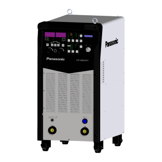
Inverter controlled GMAW DC Power Source
Before operating this product, please read the instructions carefully and save this manual for future use.
Please also read the operating instructions of peripheral equipment.
First, please read the "Safety Precautions".
English version is the original instructions.
Operating Instructions
YD-400VP1YHD
Model No.
WMD078TE0PAA07
2011
Advertisement
Table of Contents
Troubleshooting

Related Manuals for Panasonic YD-400VP1YHD


Summary of Contents for Panasonic YD-400VP1YHD
- Page 1 Operating Instructions Inverter controlled GMAW DC Power Source YD-400VP1YHD Model No. Before operating this product, please read the instructions carefully and save this manual for future use. Please also read the operating instructions of peripheral equipment. First, please read the “Safety Precautions”.
-
Page 2: Introduction
tained in this instruction manual, or user’s misus- Disclaimer age, mishandle, operational miss or abnormal Panasonic Smart Factory Solutions Co., Ltd., operation. (hereinafter called “PSFS”) and its affiliates • Any problem arising out of this Product or the use... -
Page 3: Table Of Contents
6.1.1 Connecting output cables ....37 Table of Contents 6.1.2 Connecting base metal (-) voltage detection wire ....... 38 6.1.3 Connecting grounding wire and input Introduction ........2 cables ..........38 6.2 Robotic welding ......40 1. Safety Precautions......5 6.2.1 Applicable robot models .... - Page 4 13.4.2 DC pulsed MIG welding on aluminum 8.6.3 About FILL FLOW function (Group 3 and submenu 12) ........112 ............149 8.7 Group 4: CUSTOMIZATION settings114 13.5 Arc Spot Welding Conditions Table (Reference) CO2 gas .......150 8.7.1 Setting items ........114 8.7.2 Setting procedure (Customization setting)....
-
Page 5: Safety Precautions
1. Safety Precautions 1. Safety Precautions In addition to this section, read the “Safety Man- also the disposal of waste should be per- ual” supplied with this product. formed according to the applicable laws and Also read “Operating Instructions” supplied with regulations, and standard of your company. - Page 6 (1) Contact a Panasonic sales representatives for (6) When welding a coated steel plate, provide repair work. sufficient ventilation or wear protective (2) Follow the instructions in the operating breathing gear.
- Page 7 1. Safety Precautions maintenance or repair work, provide a fence or (2) When welding or monitoring welding operation, similar form of protection around the welding wear protective clothing designed for welding, machine to prevent unauthorized individuals such as leather gloves, leg covers and a leather from accidentally coming close to the area.
-
Page 8: Specifications
2. Specifications 2. Specifications 2.1 Welding machine Model YD-400VP1YHD Rated input voltage 400 V (360 V to 440 V) (Allowable fluctuation range) Number of phases 3-phase Rated frequency 50 Hz/60 Hz (Common) 17.8 kVA Rated input 16.0 kW Efficiency 82 %... -
Page 9: Standard Accessories
2. Specifications Note About EMC classification (Class A) • This Class A equipment is not intended for use in residential locations where the electrical power is provided by the public low-voltage supply system. There can be potential difficulties in ensuring electromagnetic compatibility in those locations, due to conducted as well as radiated radio- frequency disturbances. -
Page 10: Applicable Arc Characteristics
2. Specifications 2.4 Applicable arc characteristics (*2) Wire size Wire extension (*1) Wire type Shield gas Wire material (mm) (mm) Mild steel Solid wire 15, 20 15, 20 Pulsed MAG (Flux cored wire) Stainless steel Solid wire Pulsed MIG (Flux cored wire) Solid wire Hard aluminum Pulsed MIG... -
Page 11: Rated Duty Cycle
2. Specifications 2.5 Rated duty cycle 2.6 Static characteristics and CAUTION thermal protection Static characteristics Accumulated dust on the cooling fan(s), (Constant-voltage characteristics) heat sinks, main semiconductor(s), or Voltage (V) windings can reduce allowable duty cycle or allowable weld current, which can cause deterioration or burnout of the welding machine. -
Page 12: Installation
3. Installation 3. Installation 3.1 Installation site (1) Locate indoors only, where the floor is capable of supporting the weight of the product. 40 °C (2) Avoid exposure to the direct sun light or the rain or water spray. -10 °C <Note>... -
Page 13: Transportation
3. Installation 3.2 Transportation 3.3 Power facilities WARNING Model YD-400VP1YHD Capacity Power 17.8 kVA or more Heavy load Use a crane or forklift to lift up or Fuse 30 A transfer the product. Input Breaker protect (Leakage 30 A Lifting the product by a per- ... -
Page 14: Configuration
4. Configuration 4. Configuration 4.1 What’s needed for welding operation Information - - - - - - - - - - - - - - - - - - - - - - - - - - - - - - - - Handling of wire feeder and welding torch To perform welding operation, it is necessary to •... -
Page 15: Semi-Automatic Welding
⑬ ⑧ ⑪ ⑨ ⑭ ⑧ ⑬ ⑯ ② ② ④ ④ Aluminum Mild steel/stainless steel Welding power source YD-400VP1YHD ① Wire feeder YW-40DGW2YAE Welding power ② YD-400VP1YHD ① source Gas regulator YX-503A ③ Wire feeder YW-40GD2YAD Welding torch ②... -
Page 16: Robotic Welding
⑰ Base metal cable (*): As for wire feed motor, please contact Panasonic representatives. Use a one with rotary encoder. Information - - - - - - - - - - - - - - - - - - - - - - - - - - - - - - - -... -
Page 17: Peripheral And Optional Equipment (Sold Separately)
4. Configuration 4.2 Peripheral and optional equipment (sold separately) 4.2.1 Wire feeder Mild steel/Stainless steel (Air-cooled) Aluminum (Water-cooled) Model number YW-40DG2YAD YW-40DGW2YAE Drive method Two drive rolls Four drive rolls Applicable wired dia. 1.0, 1.2 1.2, 1.6 (mm) Spool shaft With brake With brake To use a wire diameter other than the applicable one, an optional part (sold separately) is needed. -
Page 18: Gas Regulator
Mild solid YX-PDP004 CO2/MAG 1.6 mm YD-400VP1YHD steel Note Welding table expansion unit is applicable from the software version 2.00 or later. To check the current software version, please refer to "7.1.1 Operation flow" on page 60. -
Page 19: Connection Cable
4. Configuration 4.2.8 Connection cable Note Attention ================================ Usage notes of a connection cable • Keep it as stubby as possible. Do not con- nect a unnecessarily long cable. • Do not use the connection cable coiled or sagged. Keep it as straight as possible. Otherwise, arc may become unstable. - Page 20 • Connection cable unit consists of a power 20 m YV-620GB2A cable, a control cable and a gas hose cable. YV-805GB2A • Use Panasonic genuine connection cable 10 m YV-810GB2A without fail. Otherwise, cables may burn out. 80 mm 15 m YV-815GB2A •...
-
Page 21: Names And Functions
5.2.1 Terminal name 5.1 Power switch WARNING If switching the power switch to the on side does not turn on power to the unit, contact Panasonic representatives. Power switch Feeder connector Connect control cable connector of the wire feeder. Torch (+) output terminal Connect power cable of the wire feeder. -
Page 22: Rear Side Panel
5. Names and functions 5.3 Rear side panel <Connectors for robot connection> Fuse (3.15 A) A fuse for welding voltage detection. (1)Fuse (3.15 A) (2)Robot connector Robot connector Connect a control cable. (3)Encoder connector Encoder connector (4)D-sub connector Connect a control cable to receive encoder signal from the wire feeder motor. -
Page 23: Operation Panel
5. Names and functions 5.4 Operation panel Name Functions Output/Setting dis- When Mode indicator ( ) “WELD” is lit: play1 • It indicates the set value (current, wire feed speed or thickness) of the item selected by Output/Setting display1 select button ( ) in Initial ( ), Main (... - Page 24 5. Names and functions Name Functions Output/Setting dis- When Mode indicator ( ) “RECORD” (see page 117 page) is lit: play1 • Immediately after switching to RECORD mode, or when oFF is selected using Dial 2 ( ), it indicates the current set value and “- - -” alternately.
- Page 25 5. Names and functions Name Functions Output/Setting dis- When Mode indicator ( ) “WELD” is lit: play2 • It indicates the set value of the item (voltage, adjusting value based on unitary condition, or arc spot time (only when the arc spot is set)) selected by Output/Setting display2 select button ( ) in Initial ), Main (...
- Page 26 5. Names and functions Name Functions Output/Setting dis- When Mode indicator ( ) “RECORD” is lit (see page 117 page): play2 • Immediately after switching to RECORD mode, or when oFF is selected using Dial 2 ( ), it indicates the voltage set value and “oFF”...
- Page 27 5. Names and functions Name Functions Output/Setting dis- Use it to select voltage setting value, voltage adjusting value based on play2 unitary condition, or arc spot time. • Press the button until the LED of the intended Output/Setting dis- select button play 2 item indicator ( ) is lit.
- Page 28 5. Names and functions Name Functions Initial current [INI- When Mode indicator ( ) “WELD” is lit and the selected control TIAL] button process is “Ini.&Crater”, use it to specify or change the initial condition. • For each LED of Control process indicator ( ) over this [INITIAL] button ( - LED is on, the condition is set...
- Page 29 5. Names and functions Name Functions Control process indica- It indicates control process. • Specified combination of LEDs are lit according to the control process (“No crater”, “Crater” or “Ini.&Crater”) set by [CONTROL] button ( • If the [ARC SPOT] button ( ) is pressed to use the arc spot, only [INITIAL] [MAIN]...
- Page 30 5. Names and functions Name Functions Operation lock indica- When Mode indicator ( ) “CALL” (see page 120) is lit: tor&button [LOCK]/ • Use it to set the channel to call. Enter button [ENTER] When Mode indicator ( ) “RECORD” (see page 117) is lit: •...
- Page 31 5. Names and functions Name Functions Dial 2 Use it to change the value displayed on the Output/Setting display2 (For Output/Setting display2) When Mode indicator ( ) “WELD” is lit: • Use it to specify the set value of the item (voltage, voltage adjusting value based on unitary condition, or arc spot time (only when the arc spot is set)) selected by Output/Setting display2 select button ( in Initial (...
- Page 32 5. Names and functions Name Functions Material It indicates the wire material to be applied. (FCW represents flux cored indicator wire) • The LED corresponding to the wire material selected by MATERIAL select button ( ) is lit. For “mild steel (MS)” and “stainless steel (SUS)”, LED is lit in green: Solid type (SOLID) is selected LED is lit in orange: Flux type (FCW) is selected.
- Page 33 5. Names and functions Name Functions Mode indi- It indicates a mode. cator The LED corresponding to the mode selected by mode SELECT button ) is lit. Mode Use it to select a mode. select but- The LED of Mode indicator ( ) corresponding to the specified mode is lit.
- Page 34 5. Names and functions Name Functions Gas check button Use it to perform gas check. [GAS-CHECK] • The LED above the button is lit during gas check. • Press once to flow gas. Press once again to stop gas. • In 60 seconds after starting gas check, the gas stops and the LED goes off.
-
Page 35: Operation Panel In Robotic Welding
• In case it is set to “with ENERGY SAVING”, the backlight is turned off after a specified period of time. Panasonic • In case it is set to “with GUIDE LCD CTRL” , the backlight is lit if... -
Page 36: Switches On The P.c. Board
5. Names and functions 5.5 Switches on the P.C. Board Switches on the control board are • to expand the functions of the product, and • to connect optionals. Normally, keep the default switch settings. DIP switch WARNING (SW1) Prior to working on internal parts, such as switching work, turn off power at the power distribution box and ensure safety. -
Page 37: Connection
• Do not coil the cables work. If there is no such qualified personnel, (base metal cable and please contact Panasonic representatives. torch cable) as per the • Only trained and/or qualified personnel who figure on the right. Or it... -
Page 38: Connecting Base Metal (-) Voltage Detection Wire
6. Connection 6.1.3 Connecting grounding wire and Note About coupling device input cables (1) Match the positioning marks (projection) and WARNING insert it, and then turn clockwise to lock. Use the coupling device suitable to the size of the applied output cable. Otherwise, it may Observe the following instructions to cause a cable or output terminal to burn. - Page 39 6. Connection 1) Connecting grounding wire Do not use a wrench (1) Remove the input terminal cover from the to avoid overtightening. rear side panel. (2) Connect the grounding wire to the terminal PE (ground terminal) at the far right of the Rear side terminal block.
-
Page 40: Robotic Welding
6. Connection 6.2 Robotic welding Note • Lay the base metal cable 6.2.1 Applicable robot models and torch cable as per the figure on the right (as straight as possible). Model Applicable software version GIII series 24.00 (Manufactured in June, 2016 onwards.) Do not coil the cables (base metal cable and 6.2.2 Connecting output cables... -
Page 41: Connecting Base Metal Voltage Detection Wire
6. Connection 6.2.3 Connecting base metal voltage 6.2.4 Connecting grounding wire and detection wire input cable WARNING Observe the following instructions to prevent electric shock. Turn off all power including power at the power distribution box and con- firm safety before conducting connec- tion work. - Page 42 6. Connection 1) Connecting grounding wire Do not use a wrench (1) Remove the input terminal cover from the to avoid overtightening. rear side panel. (2) Connect the grounding wire to the terminal PE (ground terminal) at the far right of the Rear side terminal block.
-
Page 43: Connecting Cables For Robot Controller
6. Connection 6.3 Connecting to other devices 6.2.5 Connecting cables for robot con- troller Use the jig terminal to apply an emergency stop or a halt to the power source from an external device, or to apply the current detection signal to <Welding power source>... -
Page 44: Jig Terminals
6. Connection 6.3.1 Jig terminals Note • Remove the shorting bar before using the terminals if inserted. Otherwise, the terminals won’t function. • Connect the start signal of the welding power source to the torch switch outlet of the wire feeder. •... -
Page 45: Digital Remote Controller
6. Connection 6.3.2 Digital remote controller This section explains functions and usage unique to YD-400VP1YHD. For standard usage and con- nection, please refer to the operating instructions of the digital remote controller. 1) Operation sheet Organic light emitting panel CONTROL... - Page 46 6. Connection 2) Panel display at start [Initial check] Check and confirm that the settings of DETAIL mode: Group 3: Submenu 03 “ANALOG RC” is set to “0: Without”. For details of the setting procedure, see “8.6 Group3: SYSTEM settings” on page 104. Y D - 0 0 D C R 1 P L E A S E W A I T...
- Page 47 6. Connection 3) What this remote controller can do ● Switching control processs ・NO CRATER ... MAIN ・CRATER ....MAIN and CRATER ・INI.&CRATER ..INITIAL, MAIN and CRATER ・ARC SPOT....ARC SPOT ● Setting welding voltage at arc spot •UNITARY ....Arc spot voltage, Voltage fine adjustment value, Arc spot time •INDIVIDUAL...Arc spot voltage, Arc spot time ●...
- Page 48 6. Connection 6) Switching welding processes * Target display letters for the specified operation are indicated in boldface. <NO CRATER> 12 0A 17 .0 V → M A I N <CRATER> 12 0A 17 .0 V 8 0A 17 .4 V I N I M A I N C R T...
- Page 49 6. Connection Setting welding voltage at arc spot Switching Welding current, Wire feed rate and Thickness UNITARY: Voltage <ARC SPOT: Voltage> <WELDING CURRENT> 12 0A 17 . 0 V on Edit Edit 12 0A 17 . 0 V → voltage voltage A R C S P O T...
- Page 50 6. Connection Functions (1) Select a function .Continued 12 0A 17 . 0 V ↑ <GAS-CHECK> → → → M A I N 12 0A 17 . 0 V 5 . G S <CH CALL> 12 0A 17 . 0 V <PULSE>...
- Page 51 6. Connection (2) Functional operation 1. CH CALL Call data of the specified CH No. to play 12 0A 17 . 0 V 1 . C H C A L L * In case of “CH-OFF”: Do not CALL. (Initial screen) (CH select: Initial screen) 12 0A 1 7.
- Page 52 6. Connection 2.CH RECORD Save or delete data of the specified CH number < CH RECORD> [Recording] (Example) 12 0A 17 . 0 V Select “CH-001”. ↓ 2 . C H R E C O R D CH - 0 01 R E C D E L (RECORD initial display)
- Page 53 6. Connection 3. Settings Adjust waveform control and wire feed rate 12 0A 17 . 0 V 3 . S E T I N G (Voltage) Edit 12 0A 17 . 0 V 12 0A 17 .
- Page 54 6. Connection Note • If “3-2. FREQ.”, “3-3. PEAK CUR”, “3-4 BASE CUR” or “3-5. WFS ADJ.”, “CH CALL” and “CH RECORD” functions are not applicable during operation. • After displaying an edit screen by pressing button, if you would like to edit a differ- ent item, for example from wave control to voltage, press and select “3.
- Page 55 6. Connection 4. UNITARY/INDIVIDUAL Set voltage at unitary/individual setting 12 0A 17 . 0 V 4 . U N I / I N D * ON” is indisated when “UNITARY” is selected. ↓ 12 0A 17 . 0 V 12 0A 17 .
- Page 56 6. Connection 5. GAS CHECK Perform gas check operation. 12 0A 17 . 0 V 5 . G S 12 0A 17 . 0 V Stop gas 5 . G S C K [ O F F ] 12 0A 17 .
- Page 57 6. Connection 6. PULSE • Set whether to use pulse or not 12 0A 17 . 0 V 6 . P U L S E 12 0A 17 . 0 V 12 0A 17 . 0 V 6 . P U L S E [ O N ] M A I N 12 0A 17 .
- Page 58 6. Connection 7. WELDING CONDITIONS Display weld conditions displayed on the panel of the welding power source. 12 0A 17 . 0 V 7 . W E L D C O N D (Display weld conditions) M S - S 1 ....
-
Page 59: Welding Operation
7. Welding operation 7. Welding operation 7.1 Operation procedure WARNING WARNING Prior to welding operation, ensure workplace safety to pre- Provide sufficient ventilation or vent fire, explosion and blow- wear breathing equipment. out. Toxic fumes and gases Firmly connect cables and generated during welding can ... -
Page 60: Operation Flow
• Turn on power at the power distribution box. • Turn on power at the welding power source. All LEDs and LCDs on the operation ① panel is lit for about 0.5 second. Panasonic VP1 Series Then they are turned off sequentially. ② Display1) and version number... - Page 61 7. Welding operation Pre-operation check) 2)How to check “Wire extension length” <Semi-automatic welding: distance between tip and base metal> • Welding current output value to the welding current set value is based on the following “Tip-base metal distance”. • Difference in tip-base metal distance between actual value and the value in the following table creates a difference between the actual output current and current set value.
- Page 62 7. Welding operation 2) Welding operation (1) Arc start (2) Welding operation 3) Terminating welding operation Attention ============================= After completing welding operation, leave it for three to five minutes to cool down the inside of the welding power source before turning off power at the welding power source.
-
Page 63: Specifying Welding Conditions (Material/Wire Diameter/Gas And Pulse)
7. Welding operation 7.1.2 Specifying welding conditions (material/wire diameter/gas and pulse) Display1 Display2 Material/Wire diameter/Gas Panasonic VP1 series PULSE button Dial 1 ENTER Dial 2 MODE SELECT button 1. Select a mode. Press mode SELECT button several times (No indication) until LED for WELD lis lit. - Page 64 7. Welding operation Determine the use of PULSE LED lights solidly, Select whether to use PULSE or not. while PULSE is valid → If PULSE is set to valid, the LED above the button lights solidly. If the selected welding condition is not pulse applicable type, the button is disabled and the LED above the button stays OFF state.
- Page 65 7. Welding operation Move to the wire extension length setting (Mode: DETAIL, Group: 3, Submenu: 02). Press mode SELECT button to select DETAIL and press ENTER button. Submenu number Turn Dial 1 to display “3” on the far left Group number column of Display1, and press ENTER but- ton.
-
Page 66: Specifying Control Process
7.1.3 Specifying CONTROL process 1) Setting procedure 1. Select a mode. Press mode SELECT button several times Display1 Display2 until LED for WELD lights. Panasonic VP1 series Dial1 Dial2 ENTER button MODE SELECT button Specify a control process. Press CONTROL button.. - Page 67 ○ ○ ○ Display1 Display2 ARC SPOT ー ○ ー *O: Settable item Panasonic VP1 series <Adjustment range of welding current/voltage preset values> Adjustable range [Increment] Item Current (A) Voltage (V) INITIAL 30 to 400 [2] 12.0 to 38.0 [0.2]...
-
Page 68: Checking Inching Function
CALL mode ( WELD or CALL is lit). When mode SELECT indicator for WELD or CALL is lit Inching operation is executed while Panasonic VP1 series holding down the INCHING button. → While the button is pressed, the LED above the button is lit. -
Page 69: Welding
7. Welding operation 7.2 Welding 7.2.2 CRATER Here are some points of welding operation. • Apply main welding followed by crater weld- • There are three control processes to weld. ing. (With crater welding, it is possible to fill Use CONTROL process select button to set. the pit at the weld stop) •... -
Page 70: Ini.&Crater
7. Welding operation 7.2.3 INI.&CRATER 7.2.4 CRATER REPEAT • Apply welding operation at initial current (ini- • By enabling the crater repeat (CRATER REP) set- tial welding) before main welding, and then ting, it is possible to apply repetitive crater opera- crater welding follows. -
Page 71: Arc Spot
7. Welding operation Note • The arc stops if the torch switch is turned off Previous self-hold Crater before the preset arc spot time is over. crater welding repeat • Initial welding and crater welding are not applicable. Torch switch Trep Arc: ON Gas supply... -
Page 72: Tips To Improve Welding Activity
7. Welding operation 7.2.6 Tips to improve welding activity Note Here are some adjustment processes to improve Adjust carefully as making a vast change of welding activities. parameters can make welding activities worse. * For DETAIL mode, see section “8.3 DETAIL” on page 82. - Page 73 7. Welding operation 《With PULSE》 Adjustment Submenu No. Improvement (Set value in DETAIL mode) (DETAIL mode) Create soft arc • Increase the voltage set value (Dial 2). Create hard arc • Reduce the voltage set value (Dial 2). Concentrate the arc •...
-
Page 74: Various Settings
① Specify a material, wire diameter and Display1 Display1 gas. (See section “7.1.2 Specifying select button welding conditions (material/wire diameter/gas and pulse)” on page 63.) Panasonic VP1 series For wire diameter and thickness, see the next page.) WELD WELD NAVI. - Page 75 8. Various settings 2. Specify a thickness of workpiece to be welded. Display1 Press the Display1 select button several select button times until the LED on the left side of THICKNESS is lit. CURRENT WIRE FEED m/min SPEED Use Dial1 or Remote controller to set. THICKNESS Welding current Adjuster...
- Page 76 8. Various settings <Material-based thickness to wire diameter> Reference thickness [mm] Mild steel Stainless Stainless Hard Soft Wire material Mild steel steel aluminum aluminum steel FCW 0.8 to 4.5 0.8 to 3.0 1.0 to 6.0 1.0 to 4.0 2.0 to 6.0 Wire 1.0 to 9.0 1.0 to 9.0...
-
Page 77: Weld Navi
8. Various settings 8.2 WELD NAVI. WELD NAVI. (weld navigation) is a function that determines welding conditions (current and volt- age for main welding) by specifying some setting items in order. • If WELD NAVI. is used to set welding •... - Page 78 8. Various settings Indicates set value. Submenu number ・Use Dial1 to select. Panasonic VP1 series ・Press ENTER to set. Set value ・Use Dial2 to select. ・Press ENTER to set. Dial1 ENTER button Dial2 Contents Set value Setting range Select joint type JOINT SELECT 1.FILLET...
-
Page 79: Setting Procedure (Weld Navi.)
(material/wire diameter/gas and pulse)” on page 63.) 2. Select WELD NAVI. mode Press mode SELECT button several times until LED for WELD Display1 Display2 NAVI. is lit. Panasonic VP1 series Dial1 Dial2 ENTER button mode SELECT button → Setting item is indicated on the first line of LCD. - Page 80 8. Various settings 3. Set the indicated setting item. → Turn Dial 2 to set WELD NAVI. JOINT SELECT - > 1.FILLET? (Example: Select “1. FILLET”) JOINT SELECT Direction of Dial2 rotation - > 1.FILLET? Press ENTER button. for display value rise/fall JOINT SELECT - >...
- Page 81 Turn Dial2 until the desired set value for WELDING SPEED is dis- played. Select “rEt” to return the previous setting item: THICKNESS 1. WELDING SPEED - > RETURN? Press ENTER button. → The operation panel indicates Panasonic VP1 series the automatically selected welding conditions. WMD078TE0PAA07...
-
Page 82: Detail
8.4 Group1: ADVANCED (welding parameters) settings 8.4.1 Setting items (*Submenu numbers not in use are ignored.) Indicates set value. Submenu number ・Use Dial1 to select. Panasonic VP1 series ・Press ENTER to set. Set value ・Use Dial2 to select. ・Press ENTER to set. - Page 83 8. Various settings Increment Set item Submenu # LCD display (1st line) Setting range Default Wire feed fine adjust- WFS FINE ADJ -50 to 50 (*1) ment WAVE CONTROL 1 -99 to 99 (*1) Wave control1 (*2) PULSE FREQ -99 to 99 Pulse frequency Fine tune of pulse peak PULSE WIDTH...
- Page 84 8. Various settings The following setting items require administrator’s password. Incre- Set item Submenu # LCD display (1st line) Setting range Default ment Enter password INPUT PASSWORD 0 to 255 Change password CHANGE PASSWORD 0 to 255 0: Invalid ー Panel PANEL LOCK 1: Valid...
- Page 85 8. Various settings Incre- Set item Submenu # LCD display (1st line) Setting range Default ment Impulse start IMPULSE START SW 0: Invalid ー 1: Valid 2: Automatic End pulse settings ENDPLS 0: Invalid ー 1: Valid 2: Automatic Burnback2 BURNBACK 2 0: Invalid ー...
- Page 86 8. Various settings <Terms description> Run-in speed Wave control It slows down the wire feed speed immediately after turning on the torch switch in order to Wave control2 obtain solid arc start. Current waveform Wave control1 Burnback time It is a duration of time to keep supplying the output voltage after turning off the torch switch to stop welding operation.
- Page 87 8. Various settings About pulse welding Arc width changes by change pulse waveform. Note Changing the pulse waveform significantly will block the action of globular transfer in pulse + - - welding and cause generation of spatter. + 【User setting items】 Submenu # LCD display (1st line) Remarks...
- Page 88 8. Various settings Low pulse setting (20) ) is the simplified form of the pulse cur- Low pulse welding is to create ripples of the bead specific to the low pulse welding by rent waveform ( bringing the level of Condition B part lower than the level of Condition A part periodically.
- Page 89 8. Various settings Control of penetration increase (32) <Function> <Setting procedure> It is possible to adjust penetration at arc start. It is also possible to conduct welding operation Set the submenu 32 to “1: Valid” to enable this using the same start sequence at every start to control of penetration increase function, that is, operate independently from the torch switch sig- parameters of the submenus 88 and 98 become...
- Page 90 8. Various settings About current sequence and parameters [Fig.1] Current Current Initial condition detection Main welding Crater Time Torch switch sequence Time Current sequence when the crater control is disabled. (Time from “Current detection” to “End of the main welding” ( ) <...
-
Page 91: Setting Procedure (Welding Parameters)
Press mode SELECT button to return to the beginning of the current Mode settings. 1. Select DETAIL mode Press mode SELECT button Display1 Display2 several times until LED for DETAIL is lit. Panasonic VP1 series 溶接 溶接ナビ 詳細 再生 記憶 Dial1 Dial 2 選択... - Page 92 8. Various settings → Display “00” (submenu No.) on RUN-IN SPEED the remaining columns of Dis- play1. Contents of Submenu number → The contents of the specified the submenu No. submenu is indicated on LCD. on Display1 Specify a submenu. Turn Dial1 to display a desired RUN-IN SPEED submenu No.
- Page 93 8. Various settings 6. To exist from this group and edit another group of DETAIL mode: Press mode SELECT button once. ADVANCED Turn Dial until the desired group SYSTEM number (1 to 4) is displayed. (Example: Select group “3”) To exit from DETAIL mode: Press mode SELECT button several times until LED for the desired mode is lit.
- Page 94 8. Various settings How to change the password (Submenu 41: Change password) Turn Dial2 until “41” (submenu CHANGE PASSWORD 40) is displayed on Display1, and STANDARD VALUE : 123 then press ENTER button. → Display2 indicates the current INPUT PASSWORD password.
-
Page 95: Group2: Management Related Settings
Use it to specifies the display item on the second line of LCD if there is no items (contents or set value) to indicate. Submenu number ・Use Dial1 to select. Panasonic VP1 series ・Press ENTER to set. Set value Dial1 ・Use Dial2 to select. - Page 96 8. Various settings Indicates set value Submenu number ・Use Dial1 to select. Panasonic VP1 series ・Press ENTER to set. Set value ・Use Dial2 to select. ・Press ENTER to set. Dial1 ENTER button Dial2 Contents Sub- Incre- Setting range LCD display (1st line)
- Page 97 8. Various settings Contents Sub- Incre- Setting range LCD display (1st line) menu Default ment Output management function Welding current lower WELD(A) L-LIMIT 0 to 100 limit detection set value Note Lower limit=Preset value-(Preset value x Adjustment value) )Preset value: 100 A, Adjustment value: 10 % ⇒...
- Page 98 8. Various settings Contents Sub- Incre- Setting range LCD display (1st line) menu Default ment Output management function Contact output at WELD(V) DET CONTACT 0: OFF Welding voltage upper 1: ON limit detection Motion at Welding volt- WELD(V) DET MOVE 0: Continue (Indica- age upper limit detec- tion only)
- Page 99 8. Various settings Contents Sub- Incre- Setting range LCD display (1st line) menu Default ment Output management function Accumulated arc time ARC TIME INTEGR 0: OFF ON/OFF 1: ON Check/reset arc time ARC-T INTEGR CHK 0: Check accumulation 1: Reset arc-time integrated value.
- Page 100 8. Various settings Contents Sub- Incre- Setting range LCD display (1st line) menu Default ment Output management function Fan rotation time ON/ FAN ROT-T 0: OFF 1: ON Check/reset fan rota- FAN ROT-T CHECK 0: Check tion time 1: Reset the fan rotation time Note •...
-
Page 101: Setting Procedure (Management Function)
Press mode SELECT button to return to the beginning of the current Mode settings. 1. Select DETAIL mode. Press mode SELECT button Display1 Display2 several times until LED for DETAIL is lit. Panasonic VP1 series 溶接 溶接 溶接ナビ 溶接ナビ 詳細 詳細... - Page 102 8. Various settings Specify a submenu. Turn Dial1 until the desired sub- menu No. (00 to 89) is displayed. * Check with submenu No. on MTR(A) MONITOR Display1 and/or its contents on LCD. * For menu Nos. not in use: SUB-MONITOR Those menu numbers are indi- cated on Display1 with “- - -”...
- Page 103 8. Various settings 6. To exist from this group and edit another group of DETAIL mode: Press mode SELECT button once. ADVANCED Turn Dial1 until the desired group SYSTEM number (1 to 4) is displayed. (Example: Select group 3) To exit from DETAIL mode: Press mode SELECT button sev- eral times until LED for the desired mode is lit.
-
Page 104: Group3: System Settings
8.6 Group3: SYSTEM settings 8.6.1 Setting items * Submenu numbers not in use are ignored. Indicates set value Submenu number ・Use Dial1 to select. Panasonic VP1 series ・Press ENTER to set. Set value ・Use Dial2 to select. ・Press ENTER to set. - Page 105 8. Various settings Indicates set value Submenu number ・Use Dial1 to select. Panasonic VP1 series ・Press ENTER to set. Set value ・Use Dial2 to select. ・Press ENTER to set. Dial 1 ENTER button Dial 2 Incre- Contents Submenu# LCD display (1st line)
-
Page 106: Setting Procedure (System Settings)
Press mode SELECT button to return to the beginning of the current Mode settings. 1. Select DETAIL mode. Press mode SELECT button sev- Display1 Display2 eral times until LED for DETAIL is lit. Panasonic VP1 series 溶接 溶接ナビ 詳細 再生 記憶 Dial1 Dial2 選択... - Page 107 8. Various settings Specify a submenu. OUTPUT CONTROL Turn Dial1 until the desired sub- menu No. (00 to 20) is displayed. * Check with submenu No. on Display1 and/or its contents on CRATER REP LCD. * For menu Nos. not in use: Those menu numbers are indi- LEG LENGTH CTRL cated on Display1 with “- - - - -”...
- Page 108 8. Various settings 6. To exist from this group and edit another group of DETAIL mode: Press mode SELECT button once. SYSTEM Turn Dial1 until the desired group ADVANCED number (1 to 4) is displayed. (Example: Select group1.) To exit from DETAIL mode: Press mode SELECT button until LED for the desired mode is lit.
- Page 109 8. Various settings (2) Set “Month” • Turn Dial2 clockwise to a grad- DATE/TIME uation position. '16/**/01 → • Press ENTER button. → Display2 indicates “month” based on the current setting. DATE/TIME '16/04/** → → ”Month” indication on LCD is changed to “**”. •...
- Page 110 8. Various settings (5) Set “hour”. → ”Hour” indication on LCD is DATE/TIME changed to “**”. ← 09: 41 RETURN • Turn Dial2 to set the hour, and press ENTER button. DATE/TIME (Example: Set to “10”.) ← **: 41 RETURN (6) Set “minute”.
- Page 111 8. Various settings About submenu “18.RESET” Turn Dial2 until submenu 18 (RESET) is RESET displayed, and press ENTER button. → Display2 indicates current set value. Turn Dial2 to specify reset items RESET from 0 to 2, and press ENTER but- ton.
-
Page 112: About Fill Flow Function
8. Various settings 8.6.3 About FILL FLOW function (Group 3 and submenu 12) WARNING Provide sufficient ventilation or wear breathing equipment. Toxic fumes and gases generated during welding can be hazardous. Fill flow function enables continuous gas supply. 1) Outline It enables to operate the gas solenoid valve of the wire feeder for a preset period of time, not... - Page 113 8. Various settings 5) Operation Start welding in the pro- ② Preset cess of fill flow. post-flow time • If the torch switch is turned on in the process Torch switch of fill flow, the welding In the process of operation starts with no fill flow Gas valve...
-
Page 114: Setting Items
8. Various settings 8.7 Group 4: CUSTOMIZATION settings 8.7.1 Setting items Indicates set value. Submenu No. ・Use Dial1 to select. Panasonic VP1 series ・Press ENTER to set. Set value ・Use Dial2 to select. Dial1 ・Press ENTER to set. ENTER button... - Page 115 8. Various settings 2. Specify a DETAIL group. SYSTEM Turn Dial1 until the desired group number (1 to 4) is displayed. (Example: Select group 4.) ADVANCED Direction of Dial2 rotation Press ENTER button. for display value rise/fall MANAGEMENT Clockwise Counter-clockwise SYSTEM CUSTOMIZATION WELDING SPEED...
- Page 116 8. Various settings 5. To edit other submenus of the mode: Repeat the previous procedures 3 (Specify a submenu) and 4 (Change the set value of the sub- menu) for each submenu you want to edit. (See section “8.7.1 Setting items” on page 114.) 6....
-
Page 117: Record
CALL function. 1. Select RECORD mode. Display1 Display2 Press mode SELECT button sev- eral times until LED for RECORD is lit. Panasonic VP1 series 溶接 溶接ナビ 詳細 再生 記憶 Dial1 Dial2 選択... - Page 118 8. Various settings → Confirm to store. TURN DIAL TO SEL PRESS TO RETURN. Turn Dial2 to specify the next action from below. TURN DIAL TO SEL • no: to cancel the RECORD pro- PRESS TO RETURN. cess and return to WELD mode. •...
- Page 119 8. Various settings ・Enter “12” ( : Blinking. Selected text.) <Delete text> TXT-ENTRY Turn Dial2 clockwise to display “ CH-001: 12345 < ← ” on LCD. Turn Dial2 clockwise * “ ← ” is the second to last until “←” blinks. character.
-
Page 120: Call
• Operation varies with whether to use the remote controller or not. 1. Select CALL mode. Display1 Display2 Press mode SELECT button sev- eral times until LED for CALL is lit. Panasonic VP1 series 溶接 溶接ナビ 詳細 再生 記憶 Dial1 Dial2 選択... - Page 121 8. Various settings * When remote controller is not used. Without remote control Turn Dial2 to select a channel TURN DIAL TO SEL number (CH No.) to call. Displayed alternately PRESS TO START. → ”Current set value/voltage set value” and “’CH’/’(channel number)’”...
-
Page 122: Pulse Frequency, Pulse Peak/Base Currents, Wire-Feed Adjust & Direct
Select WELD mode. 1. Display2 Press mode SELECT button sev- eral times until LED for WELD is lit. Panasonic VP1 series * SET button is enabled only in WELD mode. Dial2 Select PULSE FREQUENCY. 溶接... -
Page 123: Pulse Peak Current
“8.4.1 Setting items” on page 82. Select WELD mode. 1. Display2 Press mode SELECT button sev- eral times until LED for WELD is lit. Panasonic VP1 series * SET button is enabled only in WELD mode. Dial2 Select PULSE PEAK CURRENT. 溶接... -
Page 124: Pulse Base Current
“8.4.1 Setting items” on page 82. Select WELD mode. 1. Display2 Press mode SELECT button sev- eral times until LED for WELD is lit. Panasonic VP1 series * SET button is enabled only in WELD mode. Dial2 Select PULSE BASE CURRENT. 溶接... -
Page 125: Wire-Feed Adjust
DETAIL group. See section “8.4.1 Setting items” on page 82. select WELD mode. 1. Display2 Press mode SELECT button sev- eral times until LED for WELD is lit. Panasonic VP1 series *SET button is enable only in WELD mode. Dial2 Select WIRE-FEED ADJUST. 溶接 溶接ナビ... -
Page 126: Direct
8. Various settings 8.10.5 DIRECT A function that allows you to perform simple set- tings by allocating specific setting items, such as frequently used setting items, to its submenus. Setting items that can be allocated to DIRECT (* Submenu numbers no in use are ignored.) Submenu # Setting item Setting range... - Page 127 8. Various settings How to allocate setting items Select WELD mode. 1. Display2 Turn mode SELECT button several times until LED for WELD is lit. Panasonic VP1 series *SET button is enabled only in WELD mode. Select DIRECT. Dial2 溶接...
-
Page 128: Maintenance
• As replacement parts, make sure to use our With daily check, do simple and quick check and genuine parts for Panasonic welding machines with periodical check, check closely in every to keep its performance and functions. -
Page 129: Periodic Inspection
9. Maintenance 9.2 Periodic inspection 9.3 Inspection items CAUTION CAUTION T ensure safe inspection work, make Observe the following instructions to sure to wear protective equipment prop- ensure safety. erly. Only trained and/or skilled personnel Improper handling of the product and ... -
Page 130: Removing Dust In The Product
9. Maintenance 9.3.3 Overall inspection Mainly check the following points. • Signs of odor, tarnish and heat generation Front • Loose connections center panel • Over-tightening • Items that are difficult to check in daily inspection 9.3.4 Checking cables and ground cable (1) Remove the front center panel from the weld- 1) Check input, output and base metal... -
Page 131: Checking Consumable
9.3.7 Parts replacement conductor cable. Connecting Disconnect all connecting cables • For safety purpose, please contact Panasonic connector and signal wires for external representatives in case of replacing parts inside devices from jig terminal, the welding power source. -
Page 132: Troubleshooting
When the power (or breaker) is auto- sub numbers of such error are indicated on Dis- plays1 and 2 if occurred. (See the below figure) matically shut off, contact Panasonic representatives for repair. <Example: Error 4-2> Reclosing the product can cause physi- cal injury due to short circuit. - Page 133 10. Troubleshooting Main LCD (Contents) Class Cause Remedy ABNORMAL TEMP Rise in temperature • Leave the power switch on to cool down inside (Temperature rise error) inside this welding the welding power power source. source. • Remove the cause of the temperature rise, such as over duty cycle, foreign material near the side...
-
Page 134: When Displays Blink Irregularly
(*)The IIF unit is not applicable to this welding power source. Note If the error recurs frequently after taking the above remedy, contact Panasonic representatives. 10.2 When displays blink irregularly If a phase of the three-phase input power source input becomes open (open phase), the seven- segment displays and LEDs blink irregularly. -
Page 135: Troubleshooting Chart
For errors, self-diagnosis is not available Blowholes refer to the Troubleshooting chart. Welded tip In case of failure of peripheral components, Wire runs into the base metal contact Panasonic representatives for repair Bead turns black parts. Unstable arc Poor arc start No wire feeding... -
Page 136: Circuit Diagram
11. Circuit diagram 11. Circuit diagram WMD078TE0PAA07... -
Page 137: Parts List
12. Parts list 12. Parts list To order a replacement part, please quote the Note “Part number”. The underline (“__”) in a part number rep- The numbers in the No. column correspond to resents a given alphanumeric character, which the circled numbers in the figures. does not affect compatibility. - Page 138 12. Parts list Symbol Part name Part number Internal code Q’ty Remarks R1,R14 Resistor CEX00083 CEX00083 R2-R5, Interchangeable with Resistor YMAD112 SFW40E5R0AP R10-R13 274H40W5R0JW LF4,LF5, Ferrite core YABD125 J0KG00000014 Control board: ZUEP1 P.C. Board WSYEP10254 WSYEP10254 ZUEP1588 Communication ZUEP8 ZUEP1295_B ZUEP1295_B_ board ZUEP9...
- Page 139 12. Parts list Lower/Upper boards <On P.C. Board mounting plate> <On chassis> Symbol Part name Part number Internal code Q’ty Remarks Control TR1,TR2 WSUTU22710 WSUTU22710 transformer ZUEP2 Governor board ZUEP1555_A ZUEP1555_A_ ZUEP4 DC power source ZUEP1585 ZUEP1585_ DC power board Control WSUTU22700 WSUTU22700...
- Page 140 12. Parts list Front / Rear <Rear> <Front> Part name Part number Internal code Remarks Q’ty Symbol FAN1 Fan motor MTND000114AA MTND000114AA Fan guard: MG12FG FAN2 Fan motor YMAD145 9WG1224J103 Safety part For motor (6.3 A) Fuse BET6.3A BET6.3A Fuse holder: MTNE000564AA Available in sets with metal plug Connector WSDEX00027...
- Page 141 12. Parts list Left side Symbol Part name Part number Internal code Q’ty Remarks Main transformer WSDTU00008ZZ WSDTU00008ZZ DLU00173 DLU00173 D2,D3 Diode YMAD219 B0FFQR000001 (Maker’s No.: PC300FN61) C10,C11 Capacitor assy WSDEX00002 WSDEX00002 C16-C18 ZNR assy WSDEX00008 WSDEX00008 ZNR1-4, G1 C19,C20 Capacitor assy WSDEX00001 WSDEX00001...
- Page 142 12. Parts list Right side Symbol Part name Part number Internal code Q’ty Remarks DLU00196 DLU00196 WSDLU00003ZZ WSDLU00003ZZ Diode B0KZ00000012 B0KZ00000012 (Maker’s No.: DFA150BA160) Q2,Q3 IGBT B1JZMV000003 B1JZMV000003 (Maker’s No.: CM200DU-24NFH) C1,C21 Capacitor YABD237 LXA401LGC472 C2-C5 Capacitor assy WSDEX00007 WSDEX00007 C13-C15 Capacitor assy WSDEX00010 WSDEX00010...
-
Page 143: Welding Conditions Table
13. Welding conditions table (Reference) 13. Welding conditions table (Reference) The following are rough indications of standard welding conditions as reference data. In actual welding operation, it is necessary to set values in consideration of shape of the workpiece, weld- ing position and so on. - Page 144 13. Welding conditions table (Reference) Fillet welding (Horizontal position) (At low-speed) Wire Tip-to-work Thickness length diameter Current Voltage Speed Gas flow distance Position (mm) (mm) (mm) (m/min) (mm) (1)/(2) (L/min) 2.5-3 0.8, 0.9 70-80 17-18 0.50-0.60 10-15 3-3.5 0.9, 1.0 85-90 18-19 0.50-0.60...
- Page 145 13. Welding conditions table (Reference) Fillet welding (Flat position) Wire Tip-to-work length diameter Current Voltage Speed flow distance Thickness (mm) (mm) (mm) (m/min) (mm) (L/min) 60-65 16-17 0.30 10-15 3-3.5 70-80 17-18 0.40-0.50 10-15 3.5-4 90-130 19-20 0.40-0.50 10-15 4-4.5 120-160 20-21 0.40-0.45...
-
Page 146: Mag Welding Conditions Table: Solid Wire (Reference)
13. Welding conditions table (Reference) 13.2 MAG Welding Conditions Table: Solid wire (Reference) • MAG gas: 80% Ar and 20% CO2 Butt joint welding (Square groove joint) (At low-speed) Wire Tip-to-work diameter Root gap G Current Voltage Speed Gas flow Thickness distance (mm) -
Page 147: Mig Welding Conditions Table: Stainless Steel (Reference)
13. Welding conditions table (Reference) 13.3 MIG welding conditions table: Stainless steel (Reference) Wire diameter: 1.0 mm Root Tip-to-work Current Voltage Speed Gas flow Thickness distance Joint type (mm) (mm) (m/min) (mm) (L/min) 80-100 16-18 Butt joint 0.50 (I-shape) 90-110 16-18 80-100 16-18... -
Page 148: Aluminum Mig Welding Conditions Table (Reference)
13. Welding conditions table (Reference) 13.4 Aluminum MIG welding conditions table (Reference) • In aluminum MIG welding, poor shielding or arc off error may occur depending on welding conditions, such as, gas flow rate and material of the base metal. Make sure to specify appropriate welding conditions, that is, set the torch angle at welding to “angle of advance”, adjust the gas flow rate to... -
Page 149: Dc Pulsed Mig Welding On Aluminum
13. Welding conditions table (Reference) 13.4.2 DC pulsed MIG welding on aluminum Hard aluminum wire: A5356, Base metal: A5052 Wire Welding Welding Welding Tip-to-work Argon Posture Thickness diameter current voltage speed distance gas flow (mm) (mm) (cm/min) (mm) (L/min) 60-70 17-18 50-60 10-12... -
Page 150: (Reference) Co2 Gas
13. Welding conditions table (Reference) 13.5 Arc Spot Welding Conditions Table (Reference) CO Wire Welding Bead Thickness Tip-to-work diameter time Current Voltage diameter Gas flow (TopxBottom) distance (mm) (mm) (mm) (mm) (L/min) 0.6 x 0.6 0.5-0.75 22-24 0.6 x 0.6 0.75-1.0 0.8 x 0.8 1.25-1.5... -
Page 151: Welding Condition Recording Sheet
14. Welding condition recording sheet 14. Welding condition recording sheet • It is recommended to keep a note of the user- • For welding conditions and channel number, created welding conditions for your see section “8.9 CALL” on page 120, and “8.8 convenience. - Page 152 14. Welding condition recording sheet Channel List Channel Channel Material to be Prepared Prepared Material to be Prepared Prepared (CH) (CH) welded welded number number WMD078TE0PAA07...
- Page 153 15. Information on Disposal 15. Information on Disposal Information on Disposal for Users of Waste Electrical & Electronic Equipment (private households) This symbol on the products and/or accompanying documents means that used electrical and electronic products should not be mixed with general household waste.
- Page 154 パナソニック スマートファクトリーソリューションズ株式会社 〒 571-8502 大阪府門真市松葉町 2 番 7 号 Panasonic Smart Factory Solutions Co., Ltd. 2-7 Matsuba-cho, Kadoma City, Osaka 571-8502, Japan © Panasonic Smart Factory Solutions Co., Ltd. Printed in Japan 2018 WMD078TE0PAA07...