
Related Manuals for Dell PowerEdge XE8545


Summary of Contents for Dell PowerEdge XE8545
- Page 1 Dell EMC PowerEdge XE8545 Technical Specifications Regulatory Model: B25S Regulatory Type: B25S001 September 2021 Rev. A01...
- Page 2 A WARNING indicates a potential for property damage, personal injury, or death. © 2020 Dell Inc. or its subsidiaries. All rights reserved. Dell, EMC, and other trademarks are trademarks of Dell Inc. or its subsidiaries. Other trademarks may be trademarks of their respective owners.
-
Page 3: Table Of Contents
Contents Chapter 1: PowerEdge XE8545 system overview................5 Front view of the system..............................5 Rear view of the system..............................6 Chapter 2: Technical specifications....................8 Chassis dimensions................................9 System weight..................................9 Processor specifications..............................10 PSU specifications................................10 Cooling fan specifications..............................10 Supported operating systems............................11 System battery specifications............................ - Page 4 Chapter 5: Safety instructions.....................31 Chapter 6: Getting help.......................32 Recycling or End-of-Life service information......................32 Contacting Dell...................................32 Accessing system information by using QRL......................32 Quick Resource Locator for PowerEdge XE8545 system.................33 Receiving automated support with SupportAssist ....................33 Contents...
-
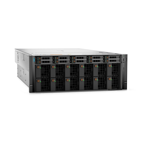
Page 5: Chapter 1: Poweredge Xe8545 System Overview
● Up to ten universal U.2/SAS/SATA hot-plug drives (maximum eight NVMe drives) NOTE: For more information about how to hot swap NVMe PCIe SSD U.2 device, see the Dell Express Flash NVMe PCIe SSD User's Guide at https://www.dell.com/support> Browse all Products > Data Center Infrastructure > Storage Adapters &... -
Page 6: Rear View Of The System
Press the system ID button: button ● To locate a particular system within a rack. ● To turn the system ID on or off. To reset iDRAC, press and hold the button for more than 16 seconds. PowerEdge XE8545 system overview... - Page 7 The NIC ports are embedded on the LOM card that is connected to the system board. Power supply unit (PSU 1) For more information on the PSU configurations, see the www.dell.com/poweredgemanuals. For more information on the ports and connectors, see the www.dell.com/poweredgemanuals. PowerEdge XE8545 system overview...
-
Page 8: Chapter 2: Technical Specifications
Technical specifications The technical and environmental specifications of your system are outlined in this section. Topics: • Chassis dimensions • System weight • Processor specifications • PSU specifications • Cooling fan specifications • Supported operating systems • System battery specifications •... -
Page 9: Chassis Dimensions
NOTE: Zb is the nominal rear wall external surface where the system board I/O connectors reside. System weight Table 4. System weight of the PowerEdge XE8545 system System configuration Maximum weight (with all drives/SSDs) 10 x 2.5-inch 48.61 kg (107.17 lb) -
Page 10: Processor Specifications
Cooling fan specifications The PowerEdge XE8545 system supports up to six very high performance gold grade (HPR (Gold)) cooling fans connected to the system board directly. The system also supports 12 very high performance fans in the front, for GPU cooling. -
Page 11: Supported Operating Systems
The PowerEdge XE8545 supports the following operating systems: ● Canonical Ubuntu Server LTS ● Microsoft Windows Server with Hyper-V ● Red Hat Enterprise Linux ● VMware ESXi ● CentOS System battery specifications The PowerEdge XE8545 system supports CR 2032 3.0-V lithium coin cell system battery. Technical specifications... -
Page 12: Expansion Card Riser Specifications
Storage controller specifications The system supports the following controller cards: Table 12. Storage controller cards for the system Internal controllers PERC H745 , H755 Drive specifications Drives The PowerEdge XE8545 system supports: ● 10 x 2.5-inch hot-swappable SAS, SATA drives. Technical specifications... -
Page 13: Ports And Connectors Specifications
● 8 x 2.5-inch hot-swappable NVMe drives. NOTE: For more information about how to hot swap NVMe PCIe SSD U.2 device, see the Dell Express Flash NVMe PCIe SSD User's Guide at https://www.dell.com/support Browse all Products > Data Center Infrastructure > Storage Adapters &... -
Page 14: Environmental Specifications
1920 x 1200 8, 16, 32 Environmental specifications NOTE: For additional information about environmental certifications, refer to the Product Environmental Datasheet located with the Manuals & Documents on www.dell.com/support/home. Table 17. Operational climatic range category A2 Temperature Specifications Allowable continuous operations Temperature ranges for altitudes <= 900 m (<=... -
Page 15: Thermal Restriction Matrix
Table 18. Shared requirements across all categories Temperature Specifications Allowable continuous operations Maximum temperature gradient (applies to both 20°C in an hour* (36°F in an hour) and 5°C in 15 minutes (41°F in 15 operation and non-operation) minutes), 5°C in an hour* (41°F in an hour) for tape NOTE: * - Per ASHRAE thermal guidelines for tape hardware, these are not instantaneous rates of temperature change. -
Page 16: Particulate And Gaseous Contamination Specifications
Table 21. Thermal restriction matrix (continued) TDP (W) Heat sink type Fan Type 2 x 2.5" SAS + 8 x 2.5" NVMe AMD Milan 24C 180W 2.55-2.65 GHz 128 MB Table 22. GPU/FPGA thermal restriction matrix TDP (W) Heat sink type Fan Type ASHRAE A2 Ambient Limit... -
Page 17: Thermal Air Restrictions
Table 24. Particulate contamination specifications (continued) Particulate contamination Specifications NOTE: Common sources of conductive dust include manufacturing processes, and zinc whiskers from the plating on the bottom of raised floor tiles Corrosive dust ● Air must be free of corrosive dust. ●... -
Page 18: Chapter 3: System Diagnostics And Indicator Codes
System diagnostics and indicator codes This section describes the diagnostic indicators on the system front panel that displays the system status during system startup. The following sections contain information about the chassis LEDs and indicator codes for the PowerEdge XE8545 system. Topics: •... - Page 19 Table 26. Status LED indicators and descriptions (continued) Icon Description Condition Corrective action If the problem persists, see the Getting help section. Electrical The indicator turns solid amber Check the System Event Log or system messages indicator if the system experiences an for the specific issue.
-
Page 20: System Health And System Id Indicator Codes
For information about the event and error messages generated by the system firmware and agents that monitor system components, go qrl.dell.com > Look Up > Error Code, type the error code, and then click Look it GPU fan LED indicator codes The GPU fan LED indicators are on the GPU fans in front of the system. -
Page 21: Idrac Direct Led Indicator Codes
The LCD panel is used to configure or view the iDRAC IP address of the system. For information about the event and error messages generated by the system firmware and agents that monitor system components, go to qrl.dell.com >... -
Page 22: Viewing Home Screen
Figure 8. LCD panel features Table 30. LCD panel features Item Button or Description display Left Moves the cursor back in one-step increments. Select Selects the menu item highlighted by the cursor. Right Moves the cursor forward in one-step increments. During message scrolling: ●... -
Page 23: View Menu
Table 31. Setup menu (continued) Option Description generated by the system firmware and agents that monitor system components, go to qrl.dell.com > Look Up > Error Code, type the error code, and then click Look it up.. Set home Select the default information to be displayed on the Home screen. See View menu section for the options and option items that can be set as the default on the Home screen. -
Page 24: Power Supply Unit Indicator Codes
Using system diagnostics If you experience an issue with the system, run the system diagnostics before contacting Dell for technical assistance. The purpose of running system diagnostics is to test the system hardware without using additional equipment or risking data loss. -
Page 25: System Board Diagnostic Led Indicators
● Run thorough tests to introduce additional test options to provide extra information about the failed device(s) ● View status messages that inform you if tests are completed successfully ● View error messages that inform you of issues encountered during testing Running the Embedded System Diagnostics from the Dell Lifecycle Controller Steps 1. - Page 26 Table 36. LED status Indicator Indicator description ○ LED Off ● LED on Blinking LED LED Off : PFAULT LED Blink : FAILSAFE Timeout LED On : FAILSAFE Strike Out Table 37. Power-up LED sequence Power-Up Sequence LED7 LED6 LED5 LED4 LED3 LED2...
- Page 27 Table 38. NvDIMM LED sequence (continued) NvDIMM ● ● ● ● ● ● ● RUN State – System operating normally ● ○ ○ ○ ● ○ ○ System powered down, NVsave in progress ● ○ ○ ● ● ○ ● NVsave complete.
- Page 28 Table 40. Pfault or failsafe errors LED sequence (continued) Pfault or Failsafe Errors ● ○ ● ○ ● CPU2 MEM345 VPP Failure ● ○ ● ● ○ CPU1 MEM012 VDDQ Failure ● ○ ● ● ● CPU1 MEM345 VDDQ Failure ●...
-
Page 29: Chapter 4: Enhanced Preboot System Assessment
Enhanced Preboot System Assessment If you experience an issue with the system, run the system diagnostics before contacting Dell for technical assistance. The purpose of running system diagnostics is to test the system hardware without requiring more equipment or risking data loss. - Page 30 7. Click OK when prompted, and the system reboots. Running the Embedded System Diagnostics from the Dell Lifecycle Controller To run the embedded system diagnostics from the Dell Lifecycle Controller: 1. As the system boots, press F10. 2. Select Hardware Diagnostics → Run Hardware Diagnostics.
-
Page 31: Chapter 5: Safety Instructions
Damage due to servicing that is not authorized by Dell is not covered by your warranty. Read and follow the safety instructions that are shipped with your product. -
Page 32: Chapter 6: Getting Help
Dell contact information on your purchase invoice, packing slip, bill or Dell product catalog. The availability of services varies depending on the country and product, and some services may not be available in your area. To contact Dell for sales, technical... -
Page 33: Quick Resource Locator For Poweredge Xe8545 System
Dell EMC. This information is used by Dell EMC Technical Support to troubleshoot the issue. ● Proactive contact — A Dell EMC Technical Support agent contacts you about the support case and helps you resolve the issue.