Table of Contents
Advertisement
Quick Links
Advertisement
Table of Contents

Related Manuals for HP FRAM71B


Summary of Contents for HP FRAM71B
- Page 1 FRAM71B 1.00 0516 Ed. 1.0 FRAM71B User’s Manual "Denver 2016" Version SW6xx_HW105...
- Page 2 "Very good, said my uncle, we will leave that to you." -Flann O´Brien, At Swim Two Birds My sincere thanks go to Robert Prosperi, Dave Frederickson, Sylvain Coté, for supporting this project. - 2 - FRAM71B 1.00 ©Hans Brueggemann, 2016...
-
Page 3: Table Of Contents
Jumpers ........................10 CN2-5: HARDCONF_C0_E0000 ................10 CN2-4: ENA_SYSRAM_WRT ..................10 CN2-3: DIS_HPBUS_WRT ..................10 CN2-2: DIS_OUT_wh_CONFIG ................. 11 CN2-1: SLCT_TOP (1 Mbyte-Option, FRAM71B-1024 only) ........11 J1: ENA_SYSRAM ..................... 11 Memory Configuration ....................12 Configuration Strings ....................15 Examples ........................ 15 Maximum Memory .................... - Page 4 Accessing the OD Signal with a Modified Module in Port #1 ....... 21 11.3 Installing an Operating System into SYSRAM ............22 11.3.1 Using FRAM71B as Shuttle between Two HP-71Bs ........22 11.3.2 Using a HEX Dump and a Serial Interface ............23 FRAM71B-512K-EXT Memory Extension ..............25 12.1...
-
Page 5: License Agreement And Copyright
Follow the installation instruction in chapter 7. Now, we can configure the amount of memory we want in our HP-71B. Say, we want an extra of 4 modules x 32 KB = 128 KByte of RAM on top of the internal 16 KByte of the calculator. -
Page 6: What Is It
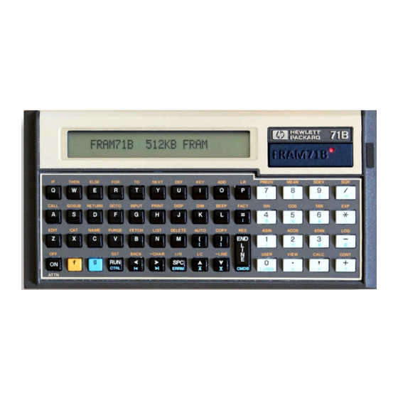
FRAM71B is a "Continuous Memory" extension for use in your Hewlett-Packard HP-71B Pocket Computer, based on FRAM technology. When plugged into the Card Reader Port, it will provide your HP-71B with up to 16 additional RAM modules of user selectable sizes and 64 KByte of system RAM. With FRAM71B you can: ·... -
Page 7: Known Incompatibilities
For the IL-Module, there is unfortunately no known way of "upgrading” its 1A ROM by using a 1B ROM-image in FRAM71B. This is due to the internal structure of the IL-Module and the way the HP-71B treats it on start-up. -
Page 8: Definition Of Terms
· IRAM: "Independent RAM”, RAM portions configured by the [FREE PORT] command. · BOT FRAM: 512 KB FRAM, available on all FRAM71B versions. · TOP FRAM: An additional 512KB FRAM, only available on an FRAM71B that has the 512 KB FRAM-Extender installed (separately available as upgrade kit). -
Page 9: Installation
5. Turn the calculator upside down and remove the Card Reader / Card Reader dummy from the compartment. 6. Insert your FRAM71B module into the Card Reader bay as shown. Gently press the mod- ule into place by pushing on the two Allen screws, until the front bezel of the module is nearly (0.5 mm) flush with HP-71B’s faceplate:... -
Page 10: Jumpers
"Disable all writes to the HP-71B bus" Default: not set (jumper removed) If set, FRAM71B will become invisible to your HP-71B, but will still accept changes to its con- figuration area (C_0x2C000 - C_0x2C01F). This is useful if your HP-71B does no longer re- spond to a RESET [ON]/[/],[3] and you need to get it back to a known state. -
Page 11: Cn2-2: Dis_Out_Wh_Config
DO NOT SET before disabling the output of the calculator’s SYSROM first. v Refer to "Using The SYSRAM Feature”. If set, FRAM71B will enable the ouput of its SYSRAM area (F_0x00000 – F_0x1FFFF). Use this feature to switch between different operating systems. SYSRAM is not affected by CN2-3. -
Page 12: Memory Configuration
User’s Manual 9 Memory Configuration The total memory space in FRAM71B is 16 x 32 KB = 512 KByte, where 32 KByte in F_Block 2 is unused, because it overlaps with HP-71B RAM (except for the configuration area). Hence, the total usable FRAM space is 480 KByte, organized in 15 F_Blocks:... - Page 13 CONF (unused) Chip_E 2C01D F_BLOCK 2C01E CONF (unused) Chip_F 2C01F F_BLOCK " Table 2: FRAM71B Configuration Sheet w/ Chip Locations. *) Chip_0 is always 32 KByte when used as HC-ROM at H_0xE0000 - 13 - FRAM71B 1.00 ©Hans Brueggemann, 2016...
- Page 14 Notes 1. A Chip that is configured to less than 32 KBytes always occupies its entire F_Block, as shown in Table 1. However, it occupies only as much of your HP-71B's address space as it is configured to. 2. Chip-addresses as "seen" by your HP-71B will vary according to the calculator’s memory configuration routine.
-
Page 15: Configuration Strings
"00 00 00 00 00 00 00 00 00 00 00 00 00 00 00 00": (32 zeroes) 0 K + 16 K = 16 KByte. This is the standard HP-71B RAM configuration when there is no other MM and FRAM71B is not configured. -
Page 16: Fram71B-1024 Example
PORT(5.01): 32 KB TOP SC ROM, holding MATHROM PORT(5.02): 32 KB BOT RAM Only available on FRAM71B-1024 In such a case, turn the HP-71B off, set jumper CN2-3, POKE the last known good configura- tion to H_2C000, remove CN2-3, and power-cycle the HP-71B. - 16 - FRAM71B 1.00... -
Page 17: Step-By-Step Configuration Example
-1024 as well. It is assumed that you have the relevant ROM images accessible on some kind of mass storage, and that you have the required HP-IL connection (be it an 82164A HP-IL/RS-232 interface, or Jean-Francois Garnier’s PILBOX) up and running. -
Page 18: Loading Chip_0 With The Hrdfrth Image And Moving It To E0000
5. PEEK$("E0000", 16) = "64 00 E4 05 0E 8F 11 EB" à success! At this point, Chip_0 has become HC ROM at address H_0xE0000 and thus "invisible" to HP- 71B's configuration routine: Although it is still listed as "93" (or, "B3" for the -1024 example) in FRAM71B's configuration string, it does no longer show up in SHOWPORT. - Page 19 5. [MEM] must display 1 x 32 KB + 16 KB à approx. 48 KB. Finally, on for some testing of the configuration: v [VER$] [END LINE] shows "HP-71:xxxxx HP-IL:xx FTH:1A EDT:1A KBD:B MATH:1A". v FORTH [ENDLINE] shows "HP-71 FORTH 1A".
-
Page 20: Using The Sysram Feature
User’s Manual 11 Using the SYSRAM Feature The SYSRAM feature allows you to switch between the HP-71B’s operating system in SYSROM and code that is located in SYSRAM. The following preparation steps are required: 1. Install the desired Operating System in SYSRAM area. -
Page 21: Accessing The Od Signal With A Modified Module In Port #1
11.2 Accessing the OD Signal with a Modified Module in Port #1 Unfortunately, the HP-71’s Card Reader bay doesn’t provide direct access to the OD signal, which is required for switching between SYSROM and SYSRAM. Hence, it must be provided by modifying a module (for example, HP82420A), which is plugged into Port #1. -
Page 22: Installing An Operating System Into Sysram
· source HP-71B ("source”), target HP-71B ("target”), FRAM71B, · optional: HP82441A FORTH/Assembler ROM Preparations: · On FRAM71B, remove J1, install CN2-4, and check CN2-1 for desired TOP or BOT set- ting. · On source, install FRAM71B. 11.3.1.1 Using PEEK$ and POKE If you aren’t using the FORTH module, run the following program on the source:... -
Page 23: Using A Hex Dump And A Serial Interface
11.3.2 Using a HEX Dump and a Serial Interface Prerequisites: · New OS as HEX dump on a PC ("source”), target HP-71B ("target”), FRAM71B. Format of HEX dump must be 2048 lines of 64 characters. · HP82401A HP-IL Interface · Either a working serial connection to the PC via 82164A HP-IL/RS-232 interface, or a USB connection via Jean-Francois Garnier’s PILBOX. - Page 24 FRAM71B User’s Manual FRAM71B Block Diagram Picture 8: FRAM71B Block diagram. Three out of 16 CONF-registers shown. - 24 - FRAM71B 1.00 ©Hans Brueggemann, 2016...
-
Page 25: Fram71B-512K-Ext Memory Extension
User’s Manual 12 FRAM71B-512K-EXT Memory Extension A standard FRAM71B-512 is equipped with a single 512 Kbyte FRAM, referred to as "BOT FRAM". The FRAM71B-512K-EXT memory extension adds another 512 KB to your FRAM71B for a total of 1024 KB of FRAM. It is referred to as "TOP-FRAM" and comes pre-installed on all FRAM71B-1024 modules. -
Page 26: General Q&A
Q3: Why is the LED indicator permanently on, even when the calculator is turned off? A: FRAM71B uses the LED as a diagnostic means. This is normal behavior while CN2-4 is set. Q4: Can I use the memory extension as a shuttle to migrate contents to another FRAM71B? A: Although possible, removal and re-insertion of the extension should be avoided due to the fragile nature of the contacts. - Page 27 As soon as you have configured more than seven modules, all trailing zeroes of the configu- ration will be read back as zeroes. Q9: The sequence to re-initialize FRAM71B after a power loss is quite tedious. Is there a short-cut to it? A: Next time you have to re-initialize FRAM71B, try this: POKE"2C000", PEEK$("2C000",32).
-
Page 28: Current Consumption
SYSRAM when the calculator is switched ON. The average current consumption of a base system plus installed FRAM71B-1024 is approx. 46 µA during OFF. Hence, with a fresh set of high- quality batteries installed, your HP-71B will sustain approx. 54000 hours (> 6 years) in OFF- state before waking up with a "MEMORY LOST”... -
Page 29: Board Connectors
FRAM71B User’s Manual 15 Board Connectors Picture 11: Physical Location of FRAM71B Board Connectors - 29 - FRAM71B 1.00 ©Hans Brueggemann, 2016... -
Page 30: Programming Cable For Actel Flashpro Programmer
Picture 12: Programming Setup. Note red cable for 3.3V supply. v During the entire upgrade process, FRAM71B requires power to be supplied from the HP-71B. Make sure that your HP-71B has fresh batteries installed and is switched OFF. - Page 31 CN3:1. Note that the wire is soldered to two pins on the CN5 side, namely pins 3 and 5. Checkerboard pattern in background is 10 x 10 mm (0.4” x 0.4”). FRAM71B requires connect- or pin at end of red cable.
-
Page 32: Note On Fram Technology
SRAM is (among others) the capability to retain memory contents without a power supply to the FRAM. Despite this fact, your HP-71B will still greet you with a MEMORY LOST message if you remove its power supply for a sufficient amount of time. This is not indicating a fault in your FRAM71B module, but is due to the fact that the HP-71B "remembers"... -
Page 33: Fram71B Configuration Sheet
FRAM71B User’s Manual 18 FRAM71B Configuration Sheet Title: Date : Module Device Size POKE "2C000", " Comment PORT (LCIM) Type [KB] 5.xx 2C000 CONF Chip_0 2C001 F_BLOCK 2C002 CONF Chip_1 2C003 F_BLOCK 2C004 CONF Chip_2 2C005 F_BLOCK 2C006 CONF Chip_3 2C007 F_BLOCK...