Table of Contents
Advertisement
Available languages
Available languages
Quick Links
デジタルゲージ /
/ Digital Gauge / Digitale Messtaster
DK812FR / DK812FR5 /
DK812FLR / DK812FLR5
お買い上げいただき、ありがとうございます。
ご使用の前に、この取扱説明書を必ずお読みください。
ご使用に際しては、この取扱説明書どおりお使いください。
。
お読みになった後は、後日お役に立つこともございますので、必ず保管してください
Read all the instructions in the manual carefully before use and strictly follow them.
Keep the manual for future references.
Lesen Sie die ganze Anleitung vor dem Betrieb aufmerksam durch und folgen Sie beim Betrieb des
Geräts den Anweisungen. Bewahren Sie diese Bedienungsanleitung zum späteren Nachlesen
griffbereit auf.
取扱説明書 / 使用说明书 / Instruction Manual /
Bedienungsanleitung
Advertisement
Table of Contents

Related Manuals for Sony DK812FR


Summary of Contents for Sony DK812FR
- Page 1 デジタルゲージ / / Digital Gauge / Digitale Messtaster DK812FR / DK812FR5 / DK812FLR / DK812FLR5 お買い上げいただき、ありがとうございます。 ご使用の前に、この取扱説明書を必ずお読みください。 ご使用に際しては、この取扱説明書どおりお使いください。 。 お読みになった後は、後日お役に立つこともございますので、必ず保管してください Read all the instructions in the manual carefully before use and strictly follow them. Keep the manual for future references. Lesen Sie die ganze Anleitung vor dem Betrieb aufmerksam durch und folgen Sie beim Betrieb des Geräts den Anweisungen.
- Page 2 [For U.S.A. and Canada] [ For EU and EFTA countries ] CE Notice THIS CLASS A DIGITAL DEVICE COMPLIES WITH Marking by the symbol CE indicates compliance with the PART15 OF THE FCC RULES AND THE CANADIAN EMC directive of the European Community. This marking I C E S - 0 0 3 .
-
Page 3: General Precautions
一般的な注意事項 General precautions When using Sony Manufacturing Systems Corporation 以下は当社製品を正しくお使いいただくための一般的注意事 products, observe the following general precautions along 項です。個々の詳細な取扱上の注意は、本取扱説明書に記述 with those given specifically in this manual to ensure proper された諸事項および注意をうながしている説明事項に従って use of the products. ください。 • 始業または操作時には、当社製品の機能および性能が正常 • Before and during operations, be sure to check that our に作動していることを確認してからご使用ください。... - Page 4 DK812FR / DK812FR5 / DK812FLR / DK812FLR5...
- Page 5 安全のために 当社の製品は安全に十分配慮して設計されています。しかし、操作や設置時にまちがった取 扱いをすると、火災や感電などにより死亡や大ケガなど人身事故につながることがあり、危 険です。また、機械の性能を落としてしまうこともあります。 これらの事故を未然に防ぐために、安全のための注意事項は必ず守ってください。操作や設 置、保守、点検、修理などを行なう前に、この「安全のために」を必ずお読みください。 警告表示の意味 このマニュアルでは、次のような表示をしています。表示内容をよく理解してから本文をお 読みください。 警告 この表示の注意事項を守らないと、火災や感電などにより死亡や大ケガなど人身事故につな がることがあります。 注意 この表示の注意事項を守らないと、感電やその他事故によりケガをしたり周辺の物品に損害 を与えることがあります。 注意を促す記号 注意 感電注意 行為を禁止する記号 分解禁止 警告 ケーブルを傷つけたり、加工したり、無理に曲げたり、引張ったりしないでくださ ・ い。また、重いものをのせたり、熱したりしないでください。ケーブルが破損し、火 災や感電の原因となる恐れがあります。 本装置を分解、改造することはおやめください。ケガや感電の恐れがあります。ま ・ た、内部回路を破損させる原因にもなります。 注意 ・ 本装置は防爆構造になっておりませんので、可燃性ガスの雰囲気中でのご使用はおや めください。火災の原因となることがあります。 (J) i...
- Page 6 ii (J)
- Page 7 使用上のご注意 • 本装置に過度の衝撃が加わる場所でのご使用はおやめください。内部を破損、または正 常な出力信号が得られないことがあります。 • コネクタの抜き差しは、破損や誤動作を防ぐため、必ず電源を切ってから行なってくだ さい。 • 接続コネクタは表示ユニットのコネクタにロックされるまで差し込みます。コネクタ着 脱の際は必ず表示ユニットの電源をOFFにしてから行なってください。 • 特に強力な磁気が発生するものは、測長ユニットから10 cm以上離してください。 • ケーブルを強く引張ったり、ケーブルをつかんで取付けや取外しをしますと、断線の恐 れがあります。 • 測長ユニットは、ケーブルのシールド線により、表示ユニットのフレームGND (アース 端子) と電気的に短絡されています。工作機械等へ取付けて他の信号処理装置と組み合 せる場合は、アースレベルにご注意ください。 • 防水型ではありませんので、直接水や油がかからないように使用してください。 • エアーリフター取付口を通じて、真空ポンプなどの利用で測定子操作をする場合には、 図1のような構成の空圧回路を用いますと、エアー駆動が可能となります。真空圧は40〜 66.7 kPa程度が適当です。また、吸排気速度をコントロールするため、専用チューブの 先には図2のようなオリフィスを設けてください。 測定子は排気により引込み操作となります。 • キャリブレーションは1年毎に行なってください。 DK812FLR / DK812FLR5 3 3 フィッティング φ0.3 フィルタ 真空発生源 VAC.側 フィッティング バルブ オリフィス 取付部...
- Page 8 取付上のご注意 • 測定子をねじ込む際、スピンドルに過大なトルクをかけますと、内部の機構を損傷する 場合がありますので、絶対に工具を用いず、手で行なってください。 平面測定子を使用される場合以外は、測定子ゆるみ防止のため、付随の呼び2.5のスプリ ングワッシャをはさむか、ねじロックのご使用をおすすめします。 (締付けトルク参考 値 : 0.05〜0.06 N・m) • 測長ユニット取付穴寸法の推奨値は、φ9.7 ±0.15 mm です。 • 取付板厚は以下のとおりです。 DK812F シリーズ: 6 〜 11 mm • 取付平行度は測定精度に影響します。 取付板の平行度および測定面に対する直角度は 0.02 mm /14 mm 以下におさえてくださ い。 • 測長ユニットの取付には、必ず付属の締め付けナット、ウェーブワッシャ、クランプスパ ナ、回り止めピンを用いてください (図1)。 ご注意 締め付け力については、ウェーブワッシャが完全に平に潰れる程度を目安としてくださ い。 推奨締付け力: 0.6 〜 1.0 N・m 最大締付け力: 2.0 N・m • ケーブルは断線を防ぐため、適当な場所へ固定するようにしてください。また、ケーブ ルを強く引いたり、無理に曲げてのご使用は避けてください。 (曲げ半径40mm (内側) 以上) • スピンドルを機械装置に固定して使用する場合には、カップリングDZ-191 (別売) をご使 用ください。DZ-191の取付方法については、DZ-191の取扱説明書をご参照ください。 • 測長ユニットに取付けるフィッティングは、図2 の形状のものを準備してください。特 にM4 ねじ部の長さ (測長ユニットにねじ込まれる部分の長さ) は、4.5 mm 以下として ください。長過ぎる場合、測長ユニットを破損することがあります。 測長ユニット O リング 回り止めピン 取付板 測長ユニット本体へ オリフィス側...
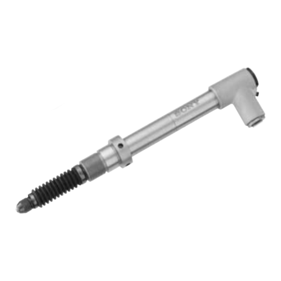
- Page 9 ■ 各部の名称 防塵ベローズ ケーブル 測定子 ステム (φ9.5 mm) エアーリフター取付口 インターポレーションBOX コネクタ DK812FLR 締め付けナット ウェーブワッシャ * イラストモデル: DK812FLR * DK812FR / DK812FR5には、エアーリフターは取付できません。 ■ 仕様 高分解能タイプ 汎用分解能タイプ DK812FR, DK812FLR DK812FR5, DK812FLR5 出力 A/B/Z相電圧差動型ラインドライバ出力 (EIA-422 準拠) 信号ピッチ 40 µm 0.1 µm 0.5 µm 最小分解能 測定範囲 12 mm 精度 (20 °Cにて) 1 µmp-p 1.5 µmp-p 12 mmストロークタイプ 下方位 : 0.6 ±0.3 N 測定力 (20 °Cにて)
- Page 10 ■ 測長ユニット出力信号 本測長ユニットが出力する信号はA/B/Z相信号でEIA-422に準拠した電圧差動型ラインドラ イバ出力です。 A相 B相 Z相 原点は、A相とB相がHiレベルのときに、Hiレベルになる同期原点です。 最大応答速度時 (約42 m/min時) の出力信号 400 ns (2.5 MHz) A相 B相 100 ns 本測長ユニットを接続する制御機、またはカウンタの入力最小位相差が100 ns (A相一周期 400 ns 2.5 MHz) より小さいことをお確かめの上ご使用ください。 ※特殊仕様にて最小位相差を変更することが可能です。 (1. 出力信号位相差参照) 1. 出力信号位相差 本測長ユニットの移動量は100 ns毎に検出され、移動量に比例した位相差で出力されます。 位相差量は、100 nsの整数倍で変化します。 また、A相とB相の最小位相差は100 nsです。 A相 B相 100 nsの整数倍 標準仕様の最小位相差は100 nsで固定ですが、下記の表の最小位相差については、特殊仕 様として対応します。 最大応答速度 A/B相最小位相差 A相一周期 カウンタの許容周波数 備考 分解能0.1 µm 分解能0.5 µm 標準品 100 ns 400 ns 2.5 MHz 42 m/min 100 m/min 特殊仕様...
- Page 11 3. 受信装置 10 m以下 受信装置 ラインドライバ ラインレシーバ AM26C32または相当品 出力: A/B/Z相 *ケーブルを延長する場合は電源電圧を+5 Vから+5.25 Vの範囲でご使用ください。 *先バラの延長ケーブルはCE22シリーズ (別売アクセサリー) をご使用ください。 ■ 別売アクセサリー • エアーリフター : DZ-801 測定スピンドルの手動操作に便利なエアーリフターが用意されています。 DK812FLR / DK812FLR5との組合せで使用できます。 • 延長ケーブル CE22-01 : 1 m、CE22-03 : 3 m、CE22-05 : 5 m、CE22-10 : 10 m 先バラ線 配線色 55.5 信号 ケーブル色相 41.5 赤 +Vcc 白 青 黄 ケーブル長 1、3、5、10 m 橙 灰 緑 紫 CK-T12 : 1 m、CK-T13 : 3 m、CK-T14 : 5 m、CK-T15 : 10 m ケーブル長 1、3、5、10 m 13.6 30.5 24.3 41.5 35.5 49.5 単位: mm (J) 5...
- Page 12 ■ 外形寸法図 単位: mm DK812FR / DK812FR5 ケーブル長 2 m (29.7) 厚さ : t=21 mm 材質 : PC 締め付けナット (101) ケーブル長 0.3 m ウェーブワッシャ DK812FLR / DK812FLR5 製品は一部改良のため、予告なく外観・仕様を変更することがあります。 6 (J)
- Page 13 安全预防措施 Sony Manufacturing Systems Corporation 产品是经周密的安全性考虑而设计的。然而,在 运行或安装时不恰当的操作仍是危险的, 它可能会引起火灾、 触电而导致死亡、 重伤等人身事 故。另外,这些操作也可能损坏机器的性能。 因此,为了防止上述意外发生,请务必遵守安全注意事项,在对本装置进行操作、安装、维 修、检查、修理等工作之前,请仔细阅读本“安全预防措施” 。 警告标志的意义 本手册中使用下面的标志,在阅读正文之前请先理解它们的含义。 警告 如果不遵守该标志处的注意事项,可能会引起火灾、触电而导致死亡、重伤等人身事故。 注意 如果不遵守该标志处的注意事项, 可能会引起触电或其它事故而导致受伤、 损坏周围事物等各 种意外。 提醒注意的标志 小心 小心触电 禁止行为的标志 禁止拆卸 警告 ・ 不要损坏、加工、过度弯曲、拉、放置重物、或加热电源线,因为这可能损坏电源线而 导致火灾或电击。 ・ 不要拆卸、 改造本装置, 因为这可能会导致受伤或电击。 另外, 这些行为也可能损坏内 部线路。 注意...
- Page 14 ii (CS)
- Page 15 使用时的注意事项 • 不要在遭受强烈震动的地方使用本装置。这可能会损坏内部线路、或导致无法获得正常 输出信号。 • 为了防止损坏或误操作,在连接或断开连接器之前,一定要关闭电源。 • 将连接器插入显示单元的插口时,要一直插入到其锁定为止。插拔连接器之前,一定要 关闭显示单元的电源。 • 在产生强磁场的场所使用时,令长度测量元件离开 10 厘米以上距离。 • 如果用力拉电缆、握持电缆安装或拆卸的话,可能会造成断线。 • 探测器主体通过电缆的屏蔽线与显示单元的外壳 GND(地线端子)之间电路上处于连接 状态。将其安装到作业机械等与其它信号处理装置组合使用时,请注意接地电平。 • 本装置不防水,使用时请勿直接沾水或油。 • 经由气动机安装口,利用真空泵等进行测定元件操作时,使用图 1 所示的气压线路构成 可以实现空气驱动。适宜的真空压力为 40~66.7 kPa 左右。另外,为了控制抽排气速 度,请按图 2 所示在专用管先端安装节流器。 可通过排气对测定元件进行缩进操作。 • 请 1 年进行一次校准。 DK812FLR / DK812FLR5 接头...
- Page 16 安装时的注意事项 • 旋转安装测定元件时,如果对主轴施加过大的转矩,可能会损坏内部构造,因此切勿使用 工具,请用手进行安装。 除了使用平面测定元件时以外,为防止测定元件松脱,建议您在之间夹入附属的公称口径 2.5 的垫圈,或使用螺丝锁。(锁紧转矩参考值:0.05~0.06 N•m) • 长度测量元件安装孔尺寸的建议值为φ9.7 ±0.15 毫米。 • 安装板厚度如下。 DK812F 系列: 6 ~ 11 毫米 • 安装平行度会影响测量精度。 安装板的平行度及相对于测定面的直角度需控制在 0.02 毫米 /14 毫米以下。 • 安装长度测量元件时,必须使用附属的固定螺母、波状垫圈、箝形扳手、制动销(图 1)。 注意 锁紧力请以波状垫圈完全压平程度为基准。 建议锁紧力:0.6 ~ 1.0 N•m 最大锁紧力:2.0 N•m • 为防止电缆断线,请将电缆固定在适宜的场所。另外,不要用力拉和过度弯曲电缆。[弯 曲半径 40毫米(内侧)以上] •...
- Page 17 ■ 各部分名称 防尘波纹管 测定元件 电缆 中空管(φ9.5 毫米) 气动机安装口 内插盒 连接器 DK812FLR 固定螺母 波状垫圈 ∗ 图示型号:DK812FLR ∗ 无法在DK812FR/DK812FR5上安装气动机。 ■ 规格 高分辨率类型 通用分辨率类型 DK812FR, DK812FLR DK812FR5, DK812FLR5 输出 A/B/Z 相电压差动型线驱动器输出(符合 EIA-422 规定) 信号间距 40 µm 0.1 µm 0.5 µm 最小分辨率 测量范围 12 毫米...
- Page 18 ■ 长度测量元件输出信号 该长度测量元件输出的信号为 A/B/Z 相信号,为符合 EIA-422 标准的电压差动型线型驱动 器输出。 A 相 B 相 Z 相 原点是 A 相与 B 相均为 Hi 水平时,位于 Hi 水平的同期原点。 最大响应速度时(约42 米/分钟时)的输出信号 400 ns (2.5 MHz) A 相 B 相 100 ns 请确认连接该长度测量元件的控制器,或计数器的输入最小相位差小于100 ns(A 相一周期 400 ns 2.5 MHz)后开始使用。 ※如有特殊规格要求,可以改变最小相位差。(请参阅...
- Page 19 接收信号装置 10 米以下 接收信号装置 线驱动器 线接收器 AM26C32 或等同产品 输出: A/B/Z 相 ∗ 使用延长电缆时请在+5 V 至 +5.25 V的电源电压范围内使用。 ∗ 请使用CE22系列(另购附属品)的先端分线延长电缆。 ■ 另购附属品 • 气动机:DZ-801 备有便于手动操作测量主轴的气动机。 可与 DK812FLR / DK812FLR5 配合使用。 • 延长电缆 CE22-01 : 1 米,CE22-03 : 3 米,CE22-05 : 5 米,CE22-10 : 10 米 先端分线...
- Page 20 ■ 外形尺寸图 单位: 毫米 DK812FR / DK812FR5 电缆长度 2 米 (29.7) 厚度:t=21 毫米 材料:PC(氯丁橡胶) 固定螺母 电缆长度 0.3 米 (101) 波状垫圈 DK812FLR / DK812FLR5 如果对本产品的一部分进行改良,其外观和规格将发生变化,恕不另行通知。 6 (CS)
-
Page 21: Safety Precautions
Safety Precautions Sony Manufacturing Systems Corporation products are designed in full consideration of safety. However, improper handling during operation or installation is dangerous and may lead to fire, electric shock or other accidents resulting in serious injury or death. In addition, these actions may also worsen machine performance. - Page 22 ii (E)
-
Page 23: Operating Cautions
Operating Cautions • Do not use the unit in places where it may receive excessive shocks. Otherwise the inside of the unit may be damaged or the unit may become unable to produce normal output signals. • Be sure to turn off the power before connecting or disconnecting connectors in oder to prevent damage or misoperation. -
Page 24: Mounting Instructions
Mounting Instructions • If excessive torque is applied on the spindle when screwing in the feeler, the internal mechanisms can be damaged. Therefore, screw in the feeler with your hands, and never use a tool. Except when using a flat feeler, it is recommended to either attacht the supplied spring washer (nominal size: 2.5) or use a screw lock to prevent loosing of the feeler (tightening torque reference value: 0.05–0.06 N·m). -
Page 25: Names Of Parts
Cable Interpolation box DK812FLR Connector Tightening nut Wave washer • Illustration: DK812FR • The air lifter cannot be attached to the DK812FR/DK812FR5. x Specifications High-resolution models General-purpose resolution models DK812FR, DK812FLR DK812FR5, DK812FLR5 Output A/B/Z phase voltage-differential line driver output (compliant with EIA-422) Signal pitch 40 µm... - Page 26 x Measuring unit output signals The signals output from this measuring unit are phase A/B/Z signals in the form of voltage-differential line driver output complying with EIA-422. Phase A Phase B Phase Z The reference point is the synchronized reference point that is at Hi level when the phase A and phase B are at the Hi level.
-
Page 27: Optional Accessories
2. Output Signal Alarm If the response speed is exceeded, the phase A/B output from this measuring unit changes to Hi level for about 400 ms to serve as an alarm. Alarm section Phase A/B is Hi level 3. Receiver 10 m/32.8' or less Receiver Line driver... -
Page 28: Design And Specifications Are Subject To Change Without Notice
13.6/0.54" 5.5/0.22" 4.8/0.19" 30.5/1.2" 5.5/0.22" 6.2/0.24" 24.3/0.96" 41.5/1.63" 35.5/1.4" 14/0.55" 49.5/1.95" Uint: mm/inch x Dimensions Uint: mm/inch DK812FR / DK812FR5 105/4.13" Cable length: 2 m/6.6' φ9.5/ 0.37" dia. 6/0.24" (29.7/1.17") 4.2/0.17" Thickness: t=21 mm/0.83" 5.8/0.23" Material: 3/0.12" 8/0.13" Tightening nut Cable length: 0.3 m/0.96'... -
Page 29: Bedeutung Der Warnhinweise
Sicherheitsmaßnahmen Bei dem Entwurf von Sony Manufacturing Systems Corporation Produkten wird größter Wert auf die Sicherheit gelegt. Unsachgemäße Handhabung während des Betriebs oder der Installation ist jedoch gefährlich und kann zu Feuer, elektrischen Schlägen oder anderen Unfällen führen, die schwere Verletzungen oder Tod zur Folge haben können. Darüber hinaus kann falsche Behandlung die Leistung der Maschine verschlechtern. - Page 30 ii (G)
-
Page 31: Zur Besonderen Beachtung
Zur besonderen Beachtung • Das Gerät nicht in Umgebungen verwenden, wo es starken Erschütterungen ausgesetzt ist, da hierdurch das Innere des Geräts beschädigt werden könnte oder die normale Signalausgabe nicht mehr funktionieren könnte. • Unbedingt darauf achten, dass die Stromversorgung ausgeschaltet ist, bevor die Stecker abgezogen werden, damit es nicht zu Schäden oder Fehlfunktionen kommt. - Page 32 Montageanleitung • Falls beim Einschrauben des Fühlers ein zu hohes Drehmoment auf die Spindel ausgeübt wird, kann die interne Struktur beschädigt werden. Schrauben Sie daher den Fühler nie mit einem Werkzeug, sondern immer von Hand ein. Bei Verwendung eines flachen Fühlers ist es empfehlenswert eine Federscheibe mit einer Nenngröße von 2,5 zu verwenden, oder Schraubensicherungskleber aufzutragen.
-
Page 33: Technische Daten
Schaft (Durchmesser: 9,5 mm) Luftabheberanschluss Kabel Interpolationseinheit Stecker DK812FLR Spannmutter Wellenscheibe • Abbildung: DK812FLR • Lediglich der Luftabheber ist am DK812FR/DK812FR5 nicht anzubringen. x Technische Daten Modelle mit hoher Auflösung Allzweckmodelle mit normaler Auflösung DK812FR, DK812FLR DK812FR5, DK812FLR5 Ausgabe A/B/Z-Phasen-Spannungsdifferential-Leitungstreiberausgabe (entspricht EIA422) Signalteilung 40 µm... - Page 34 x Messtaster-Ausgangssignale Bei den von diesem Messtaster ausgegebenen Signalen handelt es sich um A/B/ Z-Phasensignale in Form einer Spannungsdifferential-Leitungstreiberausgabe gemäß EIA-422. A-Phase B-Phase Z-Phase Der Bezugspunkt ist der synchronisierte Bezugspunkt, der sich auf H-Niveau befindet, wenn A-Phase und B-Phase sich auf H-Niveau befinden. Ausgangssignale bei maximaler Ansprechgeschwindigkeit (bei ca.
- Page 35 2. Ausgangssignalalarm Falls die Ansprechgeschwindigkeit überschritten wird, wechselt die von diesem Messtaster ausgegebene A/B-Phase für etwa 400 ms auf H-Niveau, um als Alarm zu dienen. Alarmabschnitt A/B-Phase auf H-Niveau 3. Empfänger 10 m oder weniger Empfänger Leitungstreiber Leitungsempfänger AM26C32 oder Entsprechung Ausgabe: A/B/Z-Phase ∗...
- Page 36 CK-T12: 1 m, CK-T13: 3 m, CK-T14: 5 m, CK-T15: 10 m Kabellänge: 1, 3, 5, 10 m 13,6 30,5 24,3 41,5 35,5 49,5 Einheit: mm x Abmessungen Einheit: mm DK812FR / DK812FR5 Kabellänge: 2 m (29,7) Dicke: t=21 mm Material: PC Spannmutter (101) Kabellänge: 0,3 m Wellenscheibe DK812FLR / DK812FLR5...
- Page 37 DK812FR / DK812FR5 / DK812FLR / DK812FLR5...
- Page 38 Sony Manufacturing Systems Corporation. Le matériel contenu dans ce manuel consiste en informations qui sont la propriété de Sony Manufacturing Systems Corporation et sont destinées exclusivement à l'usage des acquéreurs de l'équipement décrit dans ce manuel.
- Page 40 ソニーマニュファクチュアリングシステムズ株式会社 〒346-0035 埼玉県久喜市清久町1-10 Sony Manufacturing Systems Corporation 1-10 Kiyoku-cho, Kuki-shi, Saitama 346-0035 Japan http://www.sonysms.co.jp/ DK812FR / DK812FR5 / DK812FLR / 2005.9 DK812FLR5 Printed in Japan 2-637-296-03 ©2005 Sony Manufacturing Systems Corporation このマニュアルは再生紙を使用しています。...