
Related Manuals for Siemens SIMATIC FM 458-1 DP


Summary of Contents for Siemens SIMATIC FM 458-1 DP
- Page 1 Contents Definitions and support Product description SIMATIC Mounting Application Module Configuring FM 458-1 DP Assembly guidelines User Manual Index Edition 03/2009 A5E01078222-02...
- Page 2 Trademarks All names identified by ® are registered trademarks of the Siemens AG. The remaining trademarks in this publication may be trademarks whose use by third parties for their own purposes could violate the rights of the owner.
-
Page 3: Table Of Contents
Contents Definitions and Support............... 1-1 Definitions....................1-1 Support ....................1-2 Product description ................2-1 Application module FM 458-1 DP ............2-1 2.1.1 Updating the Firmware of FM 458-1 DP ..........2-2 2.1.2 Application and design ................2-3 2.1.3 Performance features................2-6 2.1.4 Supplementary components.............. - Page 4 Application .................... 4-62 4.7.2.2 Configuring ................... 4-63 4.7.3 Automatic mode: Communications............4-64 4.7.3.1 Application with an S7 control and SIMATIC FM 458-1 DP application module................4-64 4.7.3.2 Configuring for S7 control and SIMATIC FM 458-1 DP application module................4-66 4.7.3.3 Inserting tabular values in the data block ..........
- Page 5 Contents 4.7.4.1 Generating a table file in the csv format..........4-84 4.7.4.2 Working with the D7-SYS additionalComponentBuilder ...... 4-86 4.7.4.3 Downloading..................4-89 4.7.4.4 Configuring the function blocks ............4-91 Parameter access technique for D7-SYS ..........4-93 4.8.1 General description of the parameter functionalityinformation .... 4-93 4.8.1.1 Parameters ...................
- Page 6 Contents Ambient conditions ................5-10 Index .............................. I-1 Application Module FM 458-1 DP - User Manual A5E01078222-02 Edition 03.2009...
-
Page 7: Definitions And Support
All of the contractual responsibilities of Siemens AG are specified in the purchase contract which includes the complete and exclusively valid warranty. The contractual warranty is neither expanded nor restricted by the information provided in these Operating Instructions. -
Page 8: Support
Service & Support In addition to our paper documentation, our complete im Internet knowledge base is available to you on the Internet at: http://www.siemens.com/automation/service&support There, you will find the following information: Newsletters providing the latest information on your products ... -
Page 9: Product Description
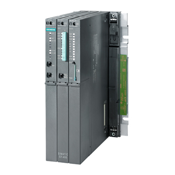
Product description Application module FM 458-1 DP Designation Order No. Application module FM 458-1 DP 6DD1607-0AA1 or 6DD1607-0AA2 The application module FM458-1 DP with the order number 6DD1607-0AA1 is replaced through the module with the order number 6DD1607-0AA2 (100 % compatible). Where two different values are specified for a feature (separated NOTE by „... -
Page 10: Updating The Firmware Of Fm 458-1 Dp
In which situations to the latest version (update). should I update the firmware? You can obtain the latest firmware versions from your Siemens partner or Where do I get the from the Internet (Siemens home page; Automation and Drives, latest version of Customer Support). -
Page 11: Application And Design
Product description 2.1.2 Application and design The FM 458-1 DP application module has been designed for high- Application performance closed-loop control and technological applications (e.g. Motion Control) which can be freely configured using CFC and optionally SFC. It is designed for use in a SIMATIC S7-400 station. Together with two additional plug-in expansion modules, the FM 458-1 DP allows a large number of high-dynamic applications, especially drive- related applications to be implemented. - Page 12 Product description The following restrictions exist when using the FM 458-1 DP application NOTES module in an S7-400 expansion controller (EC): Rack number of the EC 1..6 EC is a UR1/UR2 The coupling is realized through a K-bus capable IM pair: IM460-/461-0, or IM460-/461-3 The S7-CPU module must read-in signals from the SIMATIC I/O and send these to the FM 458-1 DP.
- Page 13 Product description Design 11 x LED INTF EXTF BUSF STOP Acknowledge button Slot for the program memory modules (MMC) PROFIBUS DP RS232 interface Binary inputs Fig. 2-2 Mechanical design of the FM 458-1 DP application module Application Module FM 458-1 DP - User Manual A5E01078222-02 Edition 03.2009...
-
Page 14: Performance Features
Product description 2.1.3 Performance features The FM 458-1 DP application module has been designed for high dynamic performance closed-loop control and technological applications in a SIMATIC S7-400 station. These control tasks can be freely configured using CFC or optionally SFC. Furthermore, it offers a PROFIBUS-DP connection. - Page 15 Product description PROFIBUS DP interface with SIMATIC compatibility equidistant (isochron) lock-cycle synchronous slave-to-slave communications capability routing, e.g. teleservice 8 alarm tasks can be called via 8 binary inputs. RS 232 interface (V.24) with service protocol DUST1 (19.2 kBd) for: ...
-
Page 16: Supplementary Components
6ES7953-8LM00-0AA0 MMC Program memory module, 8 Mbyte 6ES7953-8LP10-0AA0 PROFIBUS bus cable with PROFIBUS bus terminal Refer to Siemens, Industrial with integrated terminating resistors and plug-in Communications and Field cable Devices, Catalog IK PI 2000 e.g. 6GK1500-0AA00 PROFIBUS bus cable with PROFIBUS bus coupler... -
Page 17: Connections
Product description 2.1.5 Connections FM458-1 DP PROFIBUS cable, refer to: Siemens Industrial Communications and Field Devices Catalog IK PI 2000 SPH Communications, Volume 5 Doc. No. 720053/5 PROFIBUS DP Edition from 04.02.1999 interface Operating control unit (PC) (partial connector 1) - Page 18 Product description Serial service An operator control or configuring-PC is connected to the 9-pin sub-D socket via the SC57 PC cable. interface (X1) SC57 Designation FM-side PC-side Receive -Data In Transmit Data Out Ground 0V Enclosure Shield Table 2-3 Connector assignment of X1 and SC57 cable The binary inputs are connected at the 9-pin sub-D socket via cable Binary inputs (X2) SC64.
- Page 19 Product description PROFIBUS interface The PROFIBUS DP interface is connected to the 9-pin sub-D socket. (X3) Designation Not assigned / Ground M24V (non-isolated) Not assigned Line B (input/output) RTS from AS (input) Ground 5Vexternal, floating 5Vexternal power supply voltage, floating Not assigned / supply voltage P24V (non-isolated) Line A (input/output) RTS from PG (output)
-
Page 20: Status Displays
Product description 2.1.6 Status displays There are eleven LED displays on the front panel of the FM 458-1 DP. They provide information about its actual operating status and data for diagnostics. After the voltage runs-up, all LEDs are "DARK". Color Status Significance INTF... -
Page 21: Behavior Of The Fm458-1 Dp From The Perspective Of The S7-400 Cpu When The Operating State Changes
Product description STOP Yellow Bright STOP status The user program is not running, the module is at stop, e.g. or fatal system, initialization errors or the S7-CPU is at stop Flashing Download running in the STOP condition. Table 2-6 Significance of the LED status displays Errors can be acknowledged by pressing the acknowledge button. - Page 22 Product description Transition of the FM458-1 DP from RUN->STOP: As soon as the FM458-1 DP has reached the STOP state, the outputs of block BSEND (SFB12) are set as follows: ERROR = 0 and STATUS = 7. Behavior for POWER ON: (refer to STOP->RUN). ...
-
Page 23: Technical Data
Product description 2.1.8 Technical data Order No. Application module FM 458-1 DP 6DD1607-0AA1 / 6DD1607-0AA2 Program memory Usable MMC-Cards: 2, 4 or 8 MB Serial service RS232 interface (V.24) interface (X1) Service protocol DUST1 Data transfer rate 19.2 kbaud Binary inputs (X2) Number... -
Page 24: I/O Expansion Module Exm 438-1
Product description I/O expansion module EXM 438-1 Designation Order No. I/O expansion module EXM 438-1 6DD1607-0CA1 2.2.1 Application and design Application The EXM 438-1 expansion module provides additional binary and analog I/O as well as incremental- and absolute value encoders. Fast data transfer with the FM 458 application module is realized via the internal LE bus. -
Page 25: Performance Features
Product description 2.2.2 Performance features 8 incremental encoders: 4 absolute value encoders (SSI or EnDat) 5 analog inputs 4 analog outputs 12 Bit (analog outputs 5 - 8) 4 analog outputs 16 Bit (analog outputs 1 - 4 ) ... -
Page 26: Supplementary Components
Product description 2.2.3 Supplementary components Interface modules All of the I/O signal cables are not directly connected to the module, but via interface modules. The interface modules are used as mechanical connecting elements (screw terminals) as well as to electrically adapt the plant/system signals and convert them (optional). -
Page 27: Connection Possibilities
Product description 2.2.4 Connection possibilities EXM 438-1 EXM 438 50pin 2 incremental encoders 8 analog outputs SC63 (each 50 pin) 5 analog inputs 2 IE l=2m 8 AO SU13 5 AI 50pin SC63 6 incremental encoders (each 50 pin) l=2m 6 IE SU13 SC63... - Page 28 Product description Connecting X1 The analog inputs and outputs and a part of incremental encoders are available at the screw terminals of the SU13 interface module, which is with cable SC63 connected via cable SC63 (1:1 connection). The screw terminal assignment at interface module SU13 corresponds to the connector assignment of X1.
- Page 29 Product description Connecting X2 The incremental encoders are available at the screw terminals of interface module SU13, which is connected via cable SC63 (1:1 with cable SC63 connection). The screw terminal assignment at interface module SU13 corresponds to the connector assignment of X2. Significance Significance Increm.
- Page 30 Product description Connecting X3 The binary inputs and outputs and the absolute value encoder are available at the screw terminals of interface module SU13, which is with cable SC63 connected via cable SC63 (1:1 connection). The screw terminal assignment at interface module SU13 corresponds to the connector assignment of X3.
- Page 31 Product description Connecting X3 Depending on the required function (signal conversion, LED display), different interface modules (max. 5) can be connected to the binary with cable SC62 inputs and outputs as well as the absolute value encoder. For this particular case, cable SC62 must be used. This cable has five cable ends, which can be used to connect an appropriate number of interface modules.
- Page 32 Product description Terminal Designation SU12 SB10 SB71 assignment at Binary output 1 1/51 1/51 cable SC62, end A Binary output 2 2/52 2/52 Binary output 3 3/53 3/53 Binary output 4 4/54 4/54 Binary output 5 5/55 5/55 Binary output 6 6/56 6/56 Binary output 7...
- Page 33 Product description Terminal Designation SU12 SB10 SB61 assignment at Binary input 9 1/51 1,11/51 cable SC62, end D Binary input 10 2/52 2,12/52 Binary input 11 3/53 3,13/53 Binary input 12 4/54 4,14/54 Binary input 13 5/55 5,15/55 Binary input 14 6/56 6,16/56 Binary input 15...
-
Page 34: Incremental Encoder Settings
Product description 2.2.5 Incremental encoder settings Switches S1 and S3 are used to change over between 15V and 5V encoders. Tracks A/VW and B/RW have a common switch, track N/- of a channel has its own switch, which can be used to set the appropriate encoder type: ... -
Page 35: Cables For Ssi And Incremental Encoders
Product description 2.2.6 Cables for SSI and incremental encoders SIEMENS AG has pre-assembled cables to connect encoders to the EXM 438-1. More detailed information is provided in the Catalog "Connection Systems & System Modules for SINUMERIK, SIMODRIVE, SIMOVERT MASTERDRIVES & SIMOTION, Catalog NC Z" in its current version at a time 2.2.7... -
Page 36: Technical Data
Product description 2.2.8 Technical data Order No. /O expansion module EXM 438-1 6DD 1607 0CA1 Analog outputs Number 4 (Output 5 – 8) Electrical isolation Output voltage range - 10 V to + 10 V Output current 10 mA Resolution 12 bit Conversion time per channel, typ. - Page 37 Product description Analog inputs Number Version Differential inputs Electrical isolation Input voltage range - 10 V to + 10 V Resolution 12 bit Conversion time per channel, max approx.10 µs – 100ksps sampling rate Accuracy 1/2 LSB Integral linearity error, max.
- Page 38 Product description Binary inputs Number Electrical isolation Input voltage Permissible range -1 V to +33 V Nominal voltage 24 V For a 0 signal -1 V to + 6 V For a 1 signal +13.5 V to +33 V Input current ...
- Page 39 Product description Incremental The encoder types, corresponding to the technical data can be freely connected to the incremental encoder inputs. encoders Number Version Differential inputs, either 15V or 5V Differential inputs, either 15V encoder signals can be selected or 5V encoder signals can be selected Track signals Tracks A, B displaced through 90°...
- Page 40 Product description Voltage, currents Typical current drain Rated voltages at 25 C +5 V 1.5 A Power loss Power loss, typ. 7.5 W ambient ambient temperature max. 40 C temperature Dimensions Number of slots required in the subrack Dimensions W x H x D [mm] 24 x 290 x 210 Weight, approx.
-
Page 41: Communications Expansion Module Exm 448
Product description Communications expansion module EXM 448 Designation Order No. Communications expansion module EXM 448 6DD1607-0EA0 NOTE The EXM448 only can be installed in closed switch cabinets. 2.3.1 Application and design The EXM 448 expansion module is used as communications module for Application PROFIBUS-DP in the master- or slave function. -
Page 42: Performance Features
Product description 2.3.2 Performance features Master- or slave interface for PROFIBUS-DP incl. the functions "Shared Input“, SYNC, FREEZE Data transfer rates from 9.6 kbit/s to 12 Mbit/s Max. 127 slaves can be connected (dependent on the configuration) ... -
Page 43: Connection Possibilities
Product description 2.3.4 Connection possibilities Connecting EXM 448 diagram MASTERDRIVES- option module 9 pin PROFIBUS-DP Connector assignments: RS 232 (download) TxD = 2 RxD = 7 Grd = 1 RS 485 (PROFIBUS) +Tx/Rx = 3 -Tx/Rx = 8 Ground 5Vexternal = 5 5Vexternal = 6 Fig. - Page 44 Order No. COM PROFIBUS 6ES5 895-6SE12 (German) The "SS52 load“ driver program is included in COM PROFIBUS from V3.1, or it can be requested at no charge via the Siemens Intranet under the following address: ftp://www.erlf80.asi.siemens.de/ SIMADYN_D/html/treiber.htm 2-36 Application Module FM 458-1 DP - User Manual A5E01078222-02 Edition 03.2009...
-
Page 45: Status Displays
Product description 2.3.5 Status displays There are two LED displays provided under the upper housing cover of the EXM 448 communications expansion module. These provide information about the actual operating status. Status Diagnostics information green dark PROFIBUS not initialized flashing fatal error: 5 Hz The error code can be read at function block @CSPRO... -
Page 46: Technical Data
Product description 2.3.6 Technical data Order No. Communications expansion module 6DD1607-0EA0 EXM 448 Voltage, currents Rated voltage +5 V Typical, current drain 0.3 A Power loss Power loss, typ. 1.5 W ambient ambient temperature max. 40 C temperature Dimensions Assignment, slots Dimensions W x H x D [mm] 25 x 290 x 210 Weight... -
Page 47: Communications Expansion Module Exm 448-2
Product description Communications expansion module EXM 448-2 Designation Order No. Communications expansion module EXM 448-2 6DD1607-0EA2 2.4.1 Application and design The EXM 448-2 expansion module is used as interface module for the Application SIMOLINK drive bus and as carrier module for an additional MASTERDRIVES option module. -
Page 48: Performance Features
Product description 2.4.2 Performance features 2 SIMOLINK interfaces on board (when the plug-in modules are used, the 2 interface has no function) SIMOLINK with a master function to control up to 200 MASTERDRIVES SIMOLINK with slave function for a fast coupling to SIMADYN D or several FM 458-1 DP ... -
Page 49: Connection Possibilities
Product description 2.4.3 Connection possibilities Connecting diagram EXM 448-2 SIMOLINK X2/X3 interface 1 SIMOLINK X4/X5 interface 2 Note: For connection possibilities, connector assignments and cables, please refer to the MASTERDRIVES- documentation provided with option module the option module! Fig. 2-9 Possibilities of connecting-up the communications expansion module EXM 448-2 LE-bus connection... -
Page 50: Status Displays
Product description 2.4.4 Status displays The following LED display applies for each of the two SIMOLINK interfaces of the EXM448-2. Status Diagnostics information green dark / No net data traffic via SIMOLINK, bus cable is either not bright connected or defective. flashing Error-free net data transfer via SIMOLINK dark Simolink interface power supply faulted... -
Page 51: Mounting
Mounting Mounting the expansion modules The Order No. and the product release are printed on every Introduction SIMATIC S7-400 module. The following diagram indicates where these can be found on a module. For the product release, instead of the valid number, there is an X. A module with product release 1 is shown in the following diagram. - Page 52 Mounting Before installation in the SIMATIC subrack, you must pre-mount the FM 458-1 DP application module with all of the required options. A max. of two expansion modules can be used together with the FM 458-1 DP application module. The following combinations are possible: Application module expansion module...
- Page 53 Mounting There is a 5 x 24-pin socket to connect expansion modules to the LE bus. Removing the They are provided on the right-hand side of the FM 458-1 DP application connector- and module. This socket is protected using a removable cover. socket cover The following are provided on the EXM 438-1 and EXM 448/EXM 448-2 expansion modules...
- Page 54 Mounting Removing the Remove the cover before plugging the modules together. Proceed as follows: cover 1. Press the latch downwards (1). 2. Swivel the cover forwards (2). Fig. 3-3 Removing the cover Application Module FM 458-1 DP - User Manual A5E01078222-02 Edition 03.2009...
- Page 55 Mounting Place the FM 458-1 DP and the first expansion module on a flat surface Plugging the and carefully connect the modules, so that the connector of the modules together expansion module is inserted, with all of its pins, exactly into the socket of the FM 458-1 DP module.
- Page 56 Mounting After the modules have been plugged together lock them in place using Lock the modules the two connecting clips provided with each EXM module so that the together using the modules cannot be twisted or moved apart. Proceed as follows: connecting clips 1.
-
Page 57: Installing The Assembly Into The Simatic Subrack
Mounting Fig. 3-6 Pre-mounted module assembly with two expansion modules (schematic diagram) Installing the assembly into the SIMATIC subrack NOTE The subsequently described installation and assembly operations only refer to the FM 458-1 DP, EXM 438-1 and EXM 448/EXM 448-2 modules, which can be installed in the S7-400 automation system. -
Page 58: Application Information And Noise Immunity
Mounting Fig. 3-7 Inserting the FM 458-1 DP module (schematic diagram) 4. Screw the module at the top and bottom, tightening the screws to 0.8 ... 1.1 Nm. 5. Re-insert the line connector at the power supply module. Application information and noise immunity CAUTION The following is valid for the FM 458-1 DP application module and for the EXM 438-1 and EXM 448/EXM 448-2 expansion modules:... -
Page 59: Configuring
Operating system, compiler, function block library COM-PROFIBUS Supplementary software, if EXM 448 is to be configured as master. Detail informations: refer to www.siemens.com/fm458 Control related functions can be extremely easily configured using the Graphic graphic configuring interface CFC (Continuos Function Chart). A configuring programming language does not have to be learned. - Page 60 Configuring Fig. 4-1 View of the graphic configuring interface If the program is run on the FM 458-1 DP, the following can be directly implemented on the editor interface (CFC): actual values displayed and changed from the FM 458-1 DP, ...
-
Page 61: Configuring And Parameterizing The Components
Configuring Configuring and parameterizing the components The hardware configuration is defined in the program section of STEP 7, HWConfig in which the user indicates which components (modules) he wishes to use for his system. Configuring Arranging subracks, modules and sub-modules in a station window is known as configuring. - Page 62 Configuring Fig. 4-2 View of hardware configuration man-machine interface (screen) Basic operator Independent of the packaging technology of a station, the configuration is actions always made as follows: 1. To open the sub-directories, click on the “+“ symbol in the directory structure of the hardware catalog.
- Page 63 Configuring Corresponding to the actual machine (hardware), FM 458-1 DP modules are placed in the subrack of the S7-400 station in HWConfig; this subrack must be equipped, as a minimum with a power supply and an S7-CPU. The 400 subrack, is represented using a "configuration table", which has as many lines, as modules, which can be inserted in the actual subrack.
-
Page 64: Coupling To The Simatic S7-Cpu
Configuring Coupling to the SIMATIC S7-CPU P-bus memory The FM 458-1 DP has a RAM memory (128 Kbytes) which can be used to connect it to a P bus. Data can be exchanged with one SIMATIC S7- CPU via this P-bus memory. The FM 458-1 DP is passive on the P bus, i.e. -
Page 65: Overview Of The 3 Data Transfer Types, Fm 458-1 Dp Simatic-Cpu
Configuring 4.3.1 Overview of the 3 data transfer types, FM 458-1 DP SIMATIC-CPU Designation Number of data Configuring Speed Computation time (on the FM 458-1 DP) FM 458-1 DP: When PAS7 is Extremely low: 4 bytes to Block PAS7 called, an interrupt only for PAS7 SIMATIC-CPU... -
Page 66: Initiating A Process Interrupt On Simatic-Cpu
Configuring 4.3.2 Initiating a process interrupt on SIMATIC-CPU Function block PAS7 initiates, when triggered, a process interrupt to the PAS7 assigned S7-CPU. Supplementary interrupt info of 4 bytes is configured at the IFO input, which contains net data information. When an interrupt is initiated, the interrupt OB, which should be configured in HW Config, is called in the SIMATIC S7-CPU. -
Page 67: Data Transfer Via I/O Accesses
Configuring 4.3.3 Data transfer via I/O accesses To transfer low data quantities: up to max. 128 bytes Application Blocks and Appropriate function blocks are available for each data transfer direction and for each data type to be transferred. transfer commands SIMATIC-CPU FM 458-1 DP Data type Transfer... - Page 68 Configuring The FM 458-1 DP side is accessed using the S7RD/S7WR blocks, at Entering the offset which the offset of the data to be transferred is configured, i.e. the for FM 458-1 DP position within the 128 bytes. When assigning the offset, the number of all of the values located before the block involved (blocks) and their data type (assigned memory range in bytes) are taken into account.
- Page 69 Configuring HW Config P-bus SIMATIC S7-CPU FM 458 (CFC program) memory (SL program) of the FM 458 Send Receive Receive function blocks (read) memory (128 bytes) 1.234568e+038 S7RD PAD 512 1.234568e+38 2.000000e+000 S7RD PAD 516 1234 S7RD_I PAW 520 1234 12345678 not used! S7RD_D...
-
Page 70: Transferring Data Sets
Configuring 4.3.4 Transferring data sets If extremely large quantities of data are to be transferred, e.g. for Application visualization applications (WinCC), or if data have to be transferred between SIMATIC and FM 458-1 DP for an extremely high number of drives. - Page 71 Configuring CTS = FM4581DP.P_B Connection is connected to the P bus coupling: CFC entry: Mark the CTS/righthand mouse key/connection to the operand. The configured module name (default “FM4581DP”) appears in the selection list for the module to be connected. ...
- Page 72 Configuring SIMATIC S7 FM 458-1 DP Comments Different data types data type (CFC) data type BYTE BOOL The MSB in the byte to be sent is decisive MSB = 1, BOOL is TRUE MSB = 0, BOOL is FALSE REAL SDTIME Table 4-3 Assignment of SIMATIC S7 and SIMADYN D data types...
-
Page 73: Profibus Dp Coupling
Configuring PROFIBUS DP coupling 4.4.1 General basics Characteristics FM 458-1 DP has the following characteristics on PROFIBUS DP: Master The FM 458-1 DP communications module can be operated on PROFIBUS both alone (stand alone) and with other masters in multi- master operation. -
Page 74: Configuring The Communications In Cfc
Configuring The procedure is precisely described in the Manual “Configuring hardware and configuring connections with STEP 7 V5.2” in Chapter 3, “Configuring the distributed I/O (DP)” and Chapter 8, “Networking Stations”. This is the reason that in the following, only the special features of the FM 458-1 DP will be discussed. - Page 75 Configuring Special features when making data entries at address connection AT, AR Entries at address when using PROFIBUS DP: connection AT, AR Input sequence: "Channelname.Adressstage1.Addressstage 2" Channel name max. 8 characters ASCII characters except "Point" and @ ...
-
Page 76: Equidistance And Clock Synchronism
Configuring AT- 'Setpoint.25.1' Examples for entries at the the channel with the name setpoint transmits data to a slave address with the PROFIBUS address 25. connection AR- 'RECEIVE.117.0' the channel with the RECEIVE name receives data from a slave with PROFIBUS address 117. -
Page 77: Sync/Freeze Commands
Configuring 4.4.4 SYNC/FREEZE commands The SYNC and FREEZE commands synchronize the inputs and outputs General of a group of slaves. The SYNPRO function block initiates these commands and supports the consistency checking process. The configuring engineer is responsible in guaranteeing that data is Consistency consistent. - Page 78 Configuring Sampling time This is the cycle in which the SYNPRO function block and the transmit- and receive function blocks (on FM 458-1 DP) are calculated. The sampling time is configured using CFC. NOTE Bus circulating time and sampling time are independent of one another. ...
- Page 79 Configuring Output SOK Sampling time Synczyklus SYNC_quit SYNC_quit SYNC_command SYNC_command Bus circulating SYNC_command time Fig. 4-6 Timing diagram, SYNC version 1 When initiating the SYNC command, the transmit blocks are inhibited (SOK=0) for two sampling times (one bus circulating time). The transmit blocks are enabled in the third sampling time after initiating the SYNC command (SOK=1).
- Page 80 Configuring (FB-SYNPRO is calculating too early) Input SOK FB-SYNPRO FB-SYNPRO Sampling time Synczyklus SYNC_quit SYNC_quit SYNC_command SYNC_command SYNC_command Bus circulating time Fig. 4-7 Timing diagram, SYNC version 2 Normally, the transmit blocks are always enabled (SOK=1). If, due to time fluctuations, the SYNPRO function block is calculated before SYNC has expired (to the right in the diagram), the transmit data are not updated, but the values from the previous sampling time are transferred.
- Page 81 Configuring the length of the transmit- or receive telegram (inputs or outputs) may not exceed 32 bytes per slave. all transmit- and receive blocks and the SYNPRO function blocks must be configured in the same sampling time (on FM 458-1 DP). ...
-
Page 82: Commissioning/Diagnostics
Configuring 4.4.5 Commissioning/diagnostics 4.4.5.1 Diagnostics function block Master- or slave-specific diagnostic information can be output from General PROFIBUS DP using the DPDIAG and DPSLDG function blocks. Further information on the diagnostic data, refer to the User Documentation for the individual slaves. - Page 83 Configuring Master status Outputs information specific to the master: Output Significance Status of DP-Masters: Stop (40h), Clear (80h), Operate (C0h) Ident-No. : 80EBh for X3 on FM 458-1 DP; 8037h for SS on EXM448 / EXM448-1 Table 4-5 Information specific to the master Block DPSLDG: Slave diagnostics ...
- Page 84 Configuring Bits, status 1, 2 and 3 Bit 8 Bit 7 Bit 6 Bit 5 Bit 4 Bit 3 Bit 2 Bit 1 S: Slave Status 1 Last Erroneous Reques- Diagnos- Config. Slave still Slave (ST1) para- paramet slave ted func- tics entry data don't not ready...
-
Page 85: Error Class (Ecl) And Error Code (Eco)
Configuring Bit 7, 8 of the header byte Significance Bit 7, 8= 00 Device-related diagnostics Bit 7, 8= 01 Identification-related diagnostics Bit 7, 8= 10 Channel-related diagnostics Table 4-8 Significance of bit 7 and bit 8 of the header byte Bits 1 to 6 define the following: ... -
Page 86: Introduction "Pointer-Based Communication Blocks
Configuring Introduction "Pointer-based communication blocks" Up to D7-SYS Version 6, serial or parallel data transfer operations for SIMATIC control systems were configured using the so-called "virtual communication couplings" methods (shown in CFC charts e.g.: "!VNAME.0001"). Exception: The fiber-optic cable drive coupling SIMOLINK is configured using special SIMOLINK blocks. -
Page 87: Features Of Pointer-Based Communications
Configuring 128 bytes can be transferred from the FM 458-1 DP to the S7-CPU in Access to the I/O each direction via the I/O area of the P bus. area (P bus) for FM 458-1 DP Using the new S7RD_P/S7WR_P blocks, all 128 bytes can be copied into a buffer using a block and that with an optimized computation time. -
Page 88: Associated Function Blocks
Configuring For the same reason, this type of block communications can be principally used for all types of serial and parallel data transfer routes, where today "virtual communications" are used. 4.5.4 Associated function blocks The blocks which can be used are arranged under the family names "ZeigrKom"... -
Page 89: Pointer Interface
Configuring 4.5.5 Pointer interface For pointer-based communications, a pointer is transferred to the telegram data buffer between the blocks involved: This pointer is actually a pointer which includes a structure, which in addition to the pointer to the net data also has information for monitoring purposes. -
Page 90: Examples Of Cfc Screenshots
Configuring 4.5.7 Examples of CFC screenshots Fig. 4-9 CFC screenshot: Data transfer with telegram blocks and read/write blocks; here, for the interface P bus of the FM 458-1 DP (@CPB); bytes/words must be swapped due to the data management on the SIMATIC-CPU: SWP(Swap)=1 4-32 Application Module FM 458-1 DP - User Manual... - Page 91 Configuring Fig. 4-10 CFC screenshot: Data transfer SIMATIC-CPU FM 458-1 DP via P bus I/O area 4-33 Application Module FM 458-1 DP - User Manual A5E01078222-02 Edition 03.2009...
- Page 92 Configuring Fig. 4-11 CFC screenshot: Indexed addressing of the telegram data with 2 offsets 4-34 Application Module FM 458-1 DP - User Manual A5E01078222-02 Edition 03.2009...
- Page 93 Configuring Fig. 4-12 CFC screenshot: Re-saving 2 received telegrams in a data block and single accesses to the data memory 4-35 Application Module FM 458-1 DP - User Manual A5E01078222-02 Edition 03.2009...
- Page 94 Configuring Fig. 4-13 CFC screenshot: Large data quantities received from a SIMATIC CPU via K bus using BRCV 4-36 Application Module FM 458-1 DP - User Manual A5E01078222-02 Edition 03.2009...
-
Page 95: Simolink Drive Coupling
SIMOLINK drive coupling 4.6.1 Basic information Introduction SIMOLINK (Siemens Motion Link, SL) is a digital, serial data transfer protocol using fiber-optic cables as data transfer medium. The SIMOLINK drive coupling has been developed for extremely fast and/or rigid cycle transfer of process data (setpoints, actual values, control and status information) ... - Page 96 Configuring Bus cycle = system clock cycle Bus cycle = system bus cycle Pause SYNC Pause SYNC Pause Telegrams for Telegrams for SYNC telegram SYNC telegram data transfer data transfer between the nodes between the nodes Fig. 4-14 SIMOLINK telegram data transfer ...
-
Page 97: Application With Master-Slave Process Data Transfer
SIMOLINK). The number of channels used for each slave/transceiver is defined by the SIMOLINK function blocks (connections CTV, CSV). SIMATIC S7-400 oder SIMADYN D SIMADYN D Master SIMOLINK SIEMENS SIEMENS SIEMENS SIMOVERT SC SIMOVERT SC SIMOVERT SC 6SE7016- 1EA 30... -
Page 98: Applications And Modes Which Should Be Set
Configuring 4.6.3 Applications and modes which should be set Various SL master, dispatcher and slave modes can be set by appropriately configuring SIMOLINK. For position-synchronous actual value sensing and setpoint input (e.g. “virtual shaft” for printing or packaging machines), the jitter-free (equidistant in time) modes should be set ... - Page 99 Configuring The sampling time should be selected somewhat higher than the bus cycle time. The external-cyclic mode offers the advantage that the processor hardware of two SIMOLINK rings can be synchronized to the (common) base sampling time T0. In the external cyclic mode (Mode 5) it might happen in the case of a SIMOLINK transfer that, depending on the processing time and order of the SIMOLINK blocks, actual value and setpoint values are transferred in different scan cycles.
- Page 100 Configuring T0 interrupt SYNC telegram T0 Interrupt SYNC telegram cycle cycle Processing time of the Processing time of the SIMOLINK blocks SIMOLINK blocks Interrupt task Ix Basic clock cycle T0 Fig. 4-19 External-mode (Mode 4) The base sampling time T0 setting must correspond as a minimum to the bus cycle time plus the interrupt task processing time.
- Page 101 This technique is used, for example, to achieve synchronized processing and extremely fast data transfer between two SIMATIC FM 458-1 DP modules each with two EXM 448-1 or one EXM 448-2 expansion modules. When selecting the operating mode, it should be noted, that interrupt task Cyclic or interrupt processing can interrupt cyclic tasks at any time.
-
Page 102: Configuring - First Steps
4.6.4.1 Configuring the SIMOLINK coupling under STEP 7 For SIMATIC FM 458-1 DP with EXM 448-1, the basic clock cycle T0, possibly the interrupt task Ix and the symbolic hardware assignment for the SIMOLINK are set in the HW Config of STEP7 in the properties dialog box. - Page 103 Configuring The EXM 448-1 expansion module should be configured as EXM 448 NOTE in HWConfig. Fig. 4-24 Configuring for FM 458-1 DP with EXM448-1 4-45 Application Module FM 458-1 DP - User Manual A5E01078222-02 Edition 03.2009...
- Page 104 Configuring The basic clock cycle time must be set in HWConfig in the properties Basic clock cycle window under the "Basic clock cycle" tab. The basic sampling time must match the PWM frequency set in the MASTERDRIVE MC (the factory setting is: 5 kHz, parameter P340). The time sectors are derived from this frequency.
- Page 105 Configuring For modes 0, 2, 3 and 4, sources must be assigned to initiate the Interrupt task configured interrupt tasks. The settings are made in HW Config in the Properties window under the "Interrupt task" tab, dependent on the configured hardware components. Interrupt source to be set for interrupt task Ix of the SIMOLINK blocks, if: Mode EXM 448-1/EXM448-...
- Page 106 Configuring Fig. 4-27 Symbolic hardware assignment of an EXM 448-1 Different symbolic names are assigned for each SIMOLINK interface. For example, when configuring an ITSL module, symbolic names are entered for the integrated (TAD) and the optional SIMOLINK interface (OAD) under the "Addresses" tab: Fig.
-
Page 107: Simolink Function Blocks
Configuring 4.6.4.2 SIMOLINK function blocks The configuring engineer can use the following function blocks: @SL SIMOLINK central block SLAV SIMOLINK receive block, one for each actual value SLSV SIMOLINK send block, one for each setpoint SLSV2 SIMOLINK send block, for two setpoints ... -
Page 108: Parameterizing The Masterdrives Mc
Configuring 4.6.4.3 Parameterizing the MASTERDRIVES MC The following parameters must be set in the SIMOVERT MASTERDRIVES MC (refer to the User Documentation „MASTERDRIVES MC“): Parameter Significance/setting P740 Own node address, transceiver/slaves: 1...200 (dispatcher=0) P741 Telegram failure time, if the telegram fails, fault F056 is output. The usual values: >... - Page 109 Configuring When configuring the system, it should be noted that the number of Number of nodes nodes is restricted by the following factors: Pulse frequency set in MASTERDRIVES MC The sampling time for the time sector to be synchronized is obtained from this pulse frequency (parameter number P340).
-
Page 110: Coupling Diagnostics
Configuring 4.6.5 Coupling diagnostics The user can use the 3 LEDs on the front of the SLB module to analyze LEDs the operating status. Operating display Status Diagnostics information green flashing Error-free net data transfer via SIMOLINK flashing SLB module in operation yellow flashing Data transfer with the information processor... - Page 111 Configuring Value Diagnostics information Fault cause System response Remedy Memory access problem (internal error message) No telegram data transfer Reduce the size of the application software or move to another process module Send/receive block(s) signal: Central block @SL not configured No telegram data transfer Insert @SL in the software (min.
-
Page 112: Synchronizing Individual Simolink Rings
Configuring Value Diagnostics information Fault cause System response Remedy Mode 0: Slave attempts to write into an incorrect address Restricted telegram data transfer functions Select own slave address Logical configuring error: Slave-to-slave communications was configured as duplex operation, however, only one direction is possible for each slave (send or receive) Send and receive the same data Either configure send or receive for slave-to-slave communications Physical data transfer faulted on the SIMOLINK ring... -
Page 113: Options And Accessories
Configuring 4.6.7 Options and accessories The following are available to configure a SIMOLINK coupling and as spare part: Order No. Components 6SE7090-0XX84-0FJ0 SLB module, spare part (without documentation, without connector) 6SX7010-0FJ00 SLB module, retrofit package (documentation, 2 fiber-optic cable connectors, 5m plastic opto-cable, 1 connector for terminal X470) 6SY7000-0AD15 Attachment for SLB... -
Page 114: Introduction
(TCP/IP, DUST1, S7 via P bus). In order to transfer tabular values from an S7 control to a SIMATIC FM 458-1 DP application module via the P bus, in addition, the WR_TAB should be configured on the S7 control side (refer to Fig. -
Page 115: Overview, "Manual Mode
In the "Automatic mode: Communications", tabular values can be transferred using the following communication versions: S7 via the P bus for SIMATIC FM 458-1 DP (it is necessary to additionally configure the WR_TAB on the control side) TCP/IP (tabular values can be transferred from a SIMATIC TDC module to another one using the CTV and CRV FBs) ... - Page 116 Configuring External tables (e.g. Excel, text file) Format the table according to the entries Import tabular values in the Specify the DB at FB WR_TAB S7 control FB WR_TAB DBNUM LADDR Transfer tabular values. Communications via P bus FB TAB or FB TAB_D SIMATIC FM458...
-
Page 117: Function Block Wr_Tab
Configuring A detailed description of the "Automatic mode: Communications" mode to transfer tables from an S7 control to a SIMATIC FM 458-1 DP application module is provided in the Section "Automatic mode: Communications" (Page 4-64). 4.7.1.3 Function block WR_TAB The function block WR_TAB is used to transfer tables from one S7 control to a SIMATIC FM 458-1 DP application module. - Page 118 INPUT BOOL Last DB for the table LADDR INPUT WORD Logical address of the SIMATIC FM 458-1 DP application module RECNUM INPUT BYTE Data set number for the read and write data set FB WR_TAB does not support data set numbers 0 and 1.
- Page 119 Configuring The following errors can occur and are displayed at the ERROR output: Error code Explanation Remedy 0xB210 0xB211 Logical module address invalid Specify a valid module address at input LADDR. 0xB212 Data set number not valid Check the data set number for P bus communications.
-
Page 120: Manual Mode
Configuring 4.7.2 Manual mode 4.7.2.1 Application The "Manual mode" mode represents the simplest way of inserting tabular values into a configured software package. However, it is comparatively time consuming as data has to be manually entered or taught-in from the program. After the TAB or TAB_D has been correctly configured, the tabular values Entering tabular can be entered one after another. -
Page 121: Configuring
Configuring 4.7.2.2 Configuring For the "Manual mode", only the TAB and/or TAB_D have to be configured depending on whether tabular values, data type REAL and/or DINT have to be managed. Each table may only contain values associated with one data type. If several tables having different data types are to be managed, then an TAB or TAB_D must be configured for each table. -
Page 122: Automatic Mode: Communications
“fit” completely into a DB, then before starting the transfer, input LASTDB of the WR_TAB should be set to 1. This means that the SIMATIC FM 458-1 DP application module is signaled at the end of the data transfer. The STATUS output of the WR_TAB then changes from 2 to 0. - Page 123 WR_TAB processing time In each cycle, a telegram with 56 tabular values is transferred, from the control to the SIMATIC FM 458-1 DP application module. The time taken for a table to be transferred can be calculated as follows: Duration of the data transfer = [No.
-
Page 124: Configuring For S7 Control And Simatic Fm 458-1 Dp Application Module
Configuring for S7 control and SIMATIC FM 458-1 DP application module The following function blocks must be configured for the coupling between an S7 control and an SIMATIC FM 458-1 DP application module via P bus: SIMATIC FM 458-1 DP application module: ... -
Page 125: Inserting Tabular Values In The Data Block
4.7.3.3 Inserting tabular values in the data block In order to be able to transfer tabular values to a SIMATIC FM 458-1 DP application module, they must be available in a data block (DB). The DB should be programmed on the control side. - Page 126 Configuring The initial value is any value which can be defined for every tabular NOTE value. It is only used if there is no actual value specified for the associated tabular value. The actual value is that value which is made available as tabular value in the configured software.
- Page 127 Configuring The following diagram illustrates the selection when opening a new DB: Fig. 4-33 Making a selection when generating a new DB The opened, new DB is illustrated in the following diagram: Fig. 4-34 Newly generated DB in the application "LAD/STL/CSF" 4-69 Application Module FM 458-1 DP - User Manual A5E01078222-02...
- Page 128 Configuring (3) Entering the tabular values The required tabular values can now be entered. It should be ensured that the X and Y values are entered, alternating. To start, the data type, used in the table, should be entered (REAL or DINT).
-
Page 129: Importing Tabular Values
Configuring (4) Saving the DBs After the tabular values have been completely entered, the DB can be saved under "File Save". The tabular values are then located in the DB for transfer. 4.7.3.3.2 Importing tabular values The tabular values, provided in the DB, can also be imported from an external source, e.g. - Page 130 Configuring Fig. 4-36 An example of a table with values, data type REAL An example of a table with two X and two Y values, data type DINT is shown in the following diagram: Fig. 4-37 An example of a table with values, data type DINT 4-72 Application Module FM 458-1 DP - User Manual A5E01078222-02...
- Page 131 Configuring The following sections explain, using examples, how to re-format an From Excel to STL Excel table to obtain the required table format. The file example, shown in the following diagram, is formatted step-by- step corresponding to the specifications of the required table format. Fig.
- Page 132 Configuring Fig. 4-39 An example of a table in MS Excel with inserted header (2) Insert structure and tabular values In a next step, the structure of the tabular values and the values, specifying the data type, are inserted. In this case, two lines plus an initial and end line are inserted for each value pair.
- Page 133 Configuring Fig. 4-40 Example of a table in MS Excel with inserted structural data and tabular values (3) Saving as STL [AWL] file Finally, the correctly formatted file only has to be saved as text file with the extension *.AWL. In this case, the following should be selected in MS Excel "File ...
- Page 134 Configuring Fig. 4-41 An example of a table in MS Excel saved as text file (*.prn) After the file has been saved, the file type should be changed from *.prn to *.awl. This file can then be opened with any text editor. The following diagram shows the table example as STL [AWL] file, opened in the standard Windows text editor: Fig.
- Page 135 Configuring In addition to specifying the tabular values, it is especially important to HINWEIS specify the name of the DB. A DB is subsequently generated using the name specified in the file. In the above file example, "DB1" is specified as DB name in the first line.
- Page 136 Configuring Fig. 4-44 Selecting the file to be inserted in STEP7 as external source The selected file is opened (in this case: BEISPIELTABELLE.AWL). It now exists as source file in the configured software under "Sources". It is selected there and is opened. The file example, available under "Sources"...
- Page 137 Configuring After the file has been opened, it can be edited in the "LAD/STL/CSF" program. There it can be compiled via "File / Compile". The procedure is shown in the following diagram: Fig. 4-46 Compiling the source file in the "LAD/STL/CSF" application After the file has been successfully compiled, a new DB is available in the configured software.
- Page 138 Configuring Fig. 4-47 Newly generated DB after compiling the source file In order to check the contents of the DBs, it can be opened in the "LAD/STL/CSF" program. "Data view" should be selected in the "View" menu to display the initial (starting) values as well as the actual values. The contents of the opened DB is illustrated in the following diagram: 4-80 Application Module FM 458-1 DP - User Manual...
-
Page 139: Subsequently Downloading Tabular Values Into A Db
Configuring Fig. 4-48 Contents of the newly generated DB in the "LAD/STL/CSF" application 4.7.3.3.3 Subsequently downloading tabular values into a DB If tabular values are to be subsequently downloaded into the DB, because the table is too large and there is not sufficient user memory for several DBs, then the table should be transferred to the SIMATIC FM 458-1 DP application module in several sub-sets of the table. - Page 140 Configuring There are two possibilities: Manually enter the individual tabular parts at the DB in the "LAD/STL/CSF" application and then transfer this part of the table Generate individual source files with different names for each table sub-set and after being successfully linked-into the DB one after the other, then transfer In order to subsequently download tabular values into a DB manually, the Manual entry...
-
Page 141: Structure Of The Data Telegram For Tcp/Ip Or Dust1 Connection
Configuring 4.7.3.4 Structure of the data telegram for TCP/IP or DUST1 connection If the communications link involves a TCP/IP or DUST1 coupling, then the data telegram structure must be carefully observed. This is described in the following. The data telegrams are "generated" using the function blocks CTV and CRV. -
Page 142: Automatic Mode: Memory Card
Configuring 4.7.4 Automatic mode: Memory card Table values can be combined to form components using the D7-SYS additionalComponentBuilder (this is included in D7-SYS V5.2 plus SP1). These components can be downloaded as additional objects on the memory card. From there, they are read-out using the TAB or TAB_D function blocks. - Page 143 Configuring The table files must fulfill the following conditions: Conditions A table file may only comprise two columns – if additional columns are included in the table, an error message is displayed in a dialog window. Both of the columns must contain the same number of values. If this is not the case, then the D7-SYS additionalComponentBuilder displays an error message in a dialog window and the table values are rejected.
-
Page 144: Working With The D7-Sys Additionalcomponentbuilder
Configuring Tables, which are generated using MS Excel and are saved in the *.csv Saving tables format or as "Text (Tabs separate)“ fulfill these conditions. The following diagram shows two example files with table values which were saved in the csv format: Fig. - Page 145 Configuring New component Fig. 4-52 Setting the properties The following settings should be made: These properties cannot be changed at a later time and have a gray background. D7-SYS version List box, in which the version is specified for which the components should be generated ...
- Page 146 Configuring The new component file can be set-up after the settings have been Saving completed. The new component file is, as standard, set-up in C:\temp. If another memory path is specified, then when the program re-starts, this is used as standard memory path. Fig.
-
Page 147: Downloading
Configuring Additional table files can be added or imported or deleted at any time. The D7-SYS additionalComponentBuilder automatically takes-over the management of the table files and saves the modified component files. When opening existing components, "C:\temp“ is the standard search Opening path of the D7-SYS additionalComponentBuilder. - Page 148 Configuring (2) Opening the dialog box for optional components A maximum of 2 components can be selected. A file can be selected for the selected components by clicking on the “NEW” button. Fig. 4-56 Selection dialog box for optional components, e.g. table data (3) A file selection dialog box opens to select additional components The component file, previously created using the D7-SYS...
-
Page 149: Configuring The Function Blocks
Configuring 4.7.4.4 Configuring the function blocks For the "automatic mode, memory card" mode, only the TAB and/or TAB_D function blocks must be configured, depending as to whether table values, REAL data type and/or DINT data type have to be managed. Each table may only contain values of one data type. If several tables are to manage various data types, then a TAB or TAB_D should be configured for each table. - Page 150 Configuring Fig. 4-59 Configuring example 4-92 Application Module FM 458-1 DP - User Manual A5E01078222-02 Edition 03.2009...
-
Page 151: Parameter Access Technique For D7-Sys
Configuring Parameter access technique for D7-SYS 4.8.1 General description of the parameter functionalityinformation By appropriately parameterizing using operator control devices for parameters at the block I/O: Reading values Changing values Changing values and saving in the CPU change (cache) memory ... - Page 152 Configuring Setting parameters are configured at block inputs values can be read, changed and saved in the change memory. interconnections to other blocks can be changed using BICO technology NOTE You cannot change parameter values if $ signals or virtual connections are configured at the block inputs.
- Page 153 Configuring A parameter number may only be assigned once (checked using NOTEs the CFC). A pseudo comment may not be configured at a chart interface connection. A pseudo comment may not be configured at a block connection in a chart, which is to be compiled as block type.
-
Page 154: Bico Technology For Simadyn D
Configuring 4.8.1.2 BICO technology for SIMADYN D With MASTERDRIVES operator control devices, with BICO technology you can change interconnections between blocks. You can change configured software without using the CFC. You can change interconnections on a T400 technology board, Application module FM 458-1 DP or CPU module in a SIMADYN D subrack. - Page 155 Configuring No more than one technological connector may be configured as NOTES pseudo comment per block output. A technological connector number may only be assigned once (checked using CFC). It is not permissible to configure a technological connector at a plan interface connection.
- Page 156 Configuring The maximum number of interconnections of different inputs which NOTE are changed with BICO technology, which are saved in the change memory, are, for technology module T400: approx. 1600 Application module FM 458-1 DP: approx. 400 ...
- Page 157 Configuring Interconnection possibilities using BICO technology and their Examples significance: Pseudo- Con- Inter- Processed at the operator control device connected nection- comment Type with Read Write @TP_L/H Standard Display value Not possible @TP_L/H Flag Display value Change value @TP_L/H $ signal Display value Not possible @TP_L/H...
-
Page 158: Status-Dependent Parameter Changes
Configuring 4.8.1.3 Status-dependent parameter changes If selected parameters are only to be changed when the system is in specific statuses, then you can configure the following functions blocks: Function block PSTAT to configure a device status by entering a password with the authorization level enabled ... - Page 159 Configuring 2. User selects SRT400: If d998 = 134, then the identification routine is considered to have been successful. This means that the user can only address the technology, also independently of the basic device! The following is still valid: Parameter d999 is optional to identify the software version and release of standard software packages.
-
Page 160: Units And Unit Texts
Configuring 4.8.1.5 Units and unit texts In order that you can assign units (physical quantities) to an input or output, you must configure a text string for the block I/O from the table below. Physical quantity Units Text string to be configured Length Meters Millimeters... - Page 161 Configuring Physical quantity Units Text string to be configured Active power Watts Kilowatts Megawatts Milliwatts Apparent power Volt-ampere Kilovolt-ampere Megavolt-ampere Millivolt-ampere Speed 1 / second 1 / minute 1/min 1 / hour Angle Radian Seconds " Minutes (old) degrees grad New degrees (Gon) ngrad Velocity...
- Page 162 Configuring Physical quantity Units Text string to be configured Torque Newton meter Kilonewton meter Meganewton meter Temperature Kelvin Degrees Celsius Degrees Fahrenheit Enthalpy Joule / Kilogram J/kg Kilojoule / Kilogram kJ/kg Megajoule / Kilogram MJ/kg Voltage Volt Kilovolts Millivolts Microvolts Current Ampere Milliampere...
-
Page 163: Parameterizing On The Application Module Fm 458-1 Dp
Configuring 4.8.2 Parameterizing on the Application module FM 458-1 DP 4.8.2.1 Terminology EXM448 EXM 448 communications expansion module of the FM 458-1 DP application module CBP2 COMBOARD/communications module for PROFIBUS DP “DRIVE ES” or “DRIVE Monitor“ Configuring software for drives and software for parameterization 4.8.2.2 Communications behavior The FM 458-1 DP applications module can be configured in a SIMATIC... -
Page 164: Generating The Hardware Configuration
Configuring 4.8.2.3 Generating the hardware configuration You require the following hardware to parameterize the SIMATIC FM 458-1 DP modules: Subrack for S7-400 Power supply module for the S7-400 Central module (CPU) for S7-400 FM 458-1 DP application module for SIMATIC S7-400 ... -
Page 165: Operator Devices Which Can Be Connected
Configuring You can configure the following function blocks for additional functions: Function block CBRFAW To receive the alarms from a COMBOARD The receive block distributes values from a data interface to the block inputs of function blocks of the same CPU. Only max. -
Page 166: Wincc Connection To Fm458-1 Dp Channel (Simatic S7 Protocol Suite.chn)
Configuring WinCC connection to FM458-1 DP channel (SIMATIC S7 Protocol Suite.CHN) The chapter describes the procedure when configuring the access using WinCC to process variables (block connections) of the SIMATIC S7-400 FM458-1 DP. The various configuring and coupling options are shown in the following diagram. -
Page 167: Coupling Via Tcp/Ip With "Ocm" Functions
Configuring 4.9.1 Coupling via TCP/IP with "OCM" functions This chapter describes the procedure when configuring the WinCC access to process variables (block connections) of the SIMATIC S7-400 application module FM458-1 DP. 4.9.1.1 Configuring the coupling-relevant S7 hardware A CP443-1 ADV can be configured as communication module for the TCP/IP coupling. -
Page 168: Configuring The Cfc, Marking The Function Block Connections And Creating The Address Book
Configuring 4.9.1.2 Configuring the CFC, marking the function block connections and creating the address book The block connections, which must be handled and monitored using WinCC must, initially, be marked in the CFC charts as OCM-capable. To do this, you must proceed in the following steps: 1. - Page 169 Configuring 2. In the dialog box that is then displayed, set the checkmark for "Complete block structure", if all connections of the selected block are to be OCM-capable (refer to the following diagram). If only individual connections are to be selected then skip this step and continue with Step 3.
- Page 170 Configuring 3. Individually mark the OCM-capable connections in the WinCC attribute tab if not all of the connections are to be selected as in Step 2 (refer to the next screenshot). Select, if block connections are to be selectively selected Selectively select the block connections 4.
- Page 171 Configuring 5. Select the address book creation in the option dialog box to compile from CFC (Options Customize Compile/download) (refer to the next screenshot), in order to obtain the address information for the WinCC configuration. Activate The address book is created when compiling. This then completes all of the activities necessary in the CFC charts.
- Page 172 Configuring The DB numbers and offsets of the individual connections, necessary to configure WinCC, can now be taken from the address book. A log can be found under the menu item "Options>Logs" in which information is provided as to where the address book has been saved. Click here The location where the address book is saved is marked in the following log diagram:...
-
Page 173: Configuring Wincc
Configuring Only the WinCC-relevant information can be taken from the address book: Data block number and offset of the selected function block connections. Function chart name Function block name Data type Connector names Data block number (DB), offset 4.9.1.3 Configuring WinCC When configuring WinCC, proceed in the following steps: 1. - Page 174 Configuring 4-116 Application Module FM 458-1 DP - User Manual A5E01078222-02 Edition 03.2009...
- Page 175 Configuring 5. To do this, assign a name to the connection in the dialog box, press the properties button and enter the parameter for the connection (TCPI/IP address and slot can be taken from HW Config; refer to the following screenshot). A new TCP/IP connection is created after the dialog box is exited with 4-117 Application Module FM 458-1 DP - User Manual...
- Page 176 Configuring 6. Setting-up tags: Select the connection that has just been set-up using the righthand mouse key and select "New Tag" in the menu that is displayed. 7. In the dialog box that opens, enter a variable name (e.g. function block name_connection name, however, any other name can also be specified).
- Page 177 Configuring Offset DB Number Data type 4-119 Application Module FM 458-1 DP - User Manual A5E01078222-02 Edition 03.2009...
- Page 178 Configuring STRUC V.4.x data type D7-SYS data type Designation Bool I2 / N2 / O4 Integer I4 / N4 / O4 Double-Integer Real Byte Word Double-Word String SDTime IK, NK, CR, MR, TR, RR Global 8. After entering the appropriate data and exiting the dialog boxes with OK, a variable is set-up in WinCC for the selected block connection.
- Page 179 Configuring 11. The logical device name has to be select here. 12. Now, a reference can be made in the screen configuring to the tags that have been set-up in this way. 4-121 Application Module FM 458-1 DP - User Manual A5E01078222-02 Edition 03.2009...
-
Page 180: S7Db" Configuration Version
Configuring 4.9.2 "S7DB" configuration version When using the "S7DB_P" function block, the connection markings in the CFC charts and the creation of the address book are not required. Instead of this, the "S7DB_P" function block should be configured with the appropriate pointer-based communication blocks. The block connections, which must be accessed from WinCC, must be connected- up to the S7DB_P function block using "pointer-based communication blocks". - Page 181 Configuring DB Number Offset Data All of the other configuring steps do not differ from the procedure when using OCM functions. 4-123 Application Module FM 458-1 DP - User Manual A5E01078222-02 Edition 03.2009...
-
Page 182: Mpi And Profibus Dp Coupling Versions
Configuring 4.9.3 MPI and PROFIBUS DP coupling versions The deviations relating to either an MPI or DP coupling – that must be taken into account – are described in the following chapter. 4.9.3.1 Hardware configuration If the central MPI interface of the CPU is used, no hardware changes are required. - Page 183 Configuring 3. In the next window, insert a new "Subnet" by clicking on "New". 4. If required, change the name and open the "Network Settings" tab. 4-125 Application Module FM 458-1 DP - User Manual A5E01078222-02 Edition 03.2009...
- Page 184 Configuring 5. Select the required baud rate in the next window. 6. Close this window and set the address in the next window. Then close all of the other windows with "OK". 4-126 Application Module FM 458-1 DP - User Manual A5E01078222-02 Edition 03.2009...
- Page 185 Configuring 7. This means that the PROFIBUS DP line is configured as shown in the next screenshot. 4-127 Application Module FM 458-1 DP - User Manual A5E01078222-02 Edition 03.2009...
-
Page 186: Configuring The Cfc
Configuring 4.9.3.2 Configuring the CFC No additional function blocks have to be configured when using the MPI coupling. If the DP interface of the FM458-1 DP is to be used, then as shown in the following screenshot, function block "@PRODP" should be configured in a task between 32 and 256 ms. - Page 187 Configuring 3. Assign a name in the dialog box, press the Properties button and enter the parameters for the connection. 4. In the WinCC input screen "Connection Parameter" the station address and the slot number - as shown in the following diagram - should be taken from the HW configuration.
- Page 188 Configuring The remaining configuring steps do not differ from those associated with a TCP/IP coupling, and should therefore be taken from the previous chapter. 4-130 Application Module FM 458-1 DP - User Manual A5E01078222-02 Edition 03.2009...
-
Page 189: Configuring Using The D7-Sys-Os Engineering Tool "Mapper
Configuring 4.9.4 Configuring using the D7-SYS-OS engineering tool "Mapper" The "D7-SYS engineering tool" - also called "Mapper" in the following text - sets-up tags for the selected connectors of the CFC function blocks. These tags can then be further processed by WinCC. The following chapter describes how to use this tool. - Page 190 Configuring After the call, the target project should be selected using the lefthand "Open" icon: 4-132 Application Module FM 458-1 DP - User Manual A5E01078222-02 Edition 03.2009...
- Page 191 Configuring A Wizard is started by clicking twice on the 2nd icon (Wizard's hat): Then click on "Continue": The operator station is then selected as shown in the next screenshot: Then click on "Continue": 4-133 Application Module FM 458-1 DP - User Manual A5E01078222-02 Edition 03.2009...
- Page 192 Configuring The selection and assignment of the programs to the operator stations is then realized in the next step: Displaying the selected programs: 4-134 Application Module FM 458-1 DP - User Manual A5E01078222-02 Edition 03.2009...
- Page 193 Configuring If the connection parameters are to be checked, then click on "Connection". This is not absolutely necessary if "NetPro" has been correctly configured. However, if various couplings are used (TCP/IP, MPI or DP) then the required connection should be selected. Then click on "Continue": For smaller projects, "All"...
- Page 194 Configuring Then, start the actual mapping (transfer) process by clicking on "Transfer". Transferring (mapping) then runs: This therefore completes data transfer: End by clicking on "OK" 4-136 Application Module FM 458-1 DP - User Manual A5E01078222-02 Edition 03.2009...
- Page 195 Configuring The tags that have been created are listed in WinCC Explorer: The system parameters of the coupling, shown in the following diagrams, now have to be checked: 4-137 Application Module FM 458-1 DP - User Manual A5E01078222-02 Edition 03.2009...
- Page 196 Configuring Deactivate cycle management by the automation system: Select the device name: After changing the system parameters WinCC has to be restarted. It will be possible to access the configured variables once this has been completed. 4-138 Application Module FM 458-1 DP - User Manual A5E01078222-02 Edition 03.2009...
-
Page 197: Assembly Guidelines
Further, the contents of this Manual shall not become a part of or modify any prior or existing agreement, commitment or relationship. The sales contract contains the entire obligation of Siemens. The warranty contained in the contract between the parties is the sole warranty of Siemens. -
Page 198: Danger And Warning Information
Assembly guidelines 5.1.1.2 Danger and warning information For the purpose of this Manual and product labels, „Danger“ indicates DANGER death, severe personal injury and/or substantial property damage will result if proper precautions are not taken. WARNING For the purpose of this Manual and product labels, „Warning“ indicates death, severe personal injury or property damage can result if proper precautions are not taken. -
Page 199: Introduction
Assembly guidelines 5.1.2 Introduction Electromagnetic compatibility (EMC) is the ability of an electrical device What is EMC? to function, fault-free in a specified electromagnetic environment without influencing the environment in an inadmissible fashion. This design- and EMC guideline supplements the documentation on the individual components. -
Page 200: Standards And Certifications
Assembly guidelines 5.1.3 Standards and certifications NOTE You find detailed information to the standards and certifications in the reference manual "SIMATIC S7-400 Automation System Module Data, chapter 1, section: Standards, certificates and approvals". 5.1.3.1 FM 458-1 DP outputs DANGER When the equipment is powered-up or powered -on, the outputs have undefined statuses while the power supply voltages are running-up. -
Page 201: Subrack
Assembly guidelines 5.1.5 Subrack The subrack must be connected to the ground/potential bonding rail through the shortest possible connection using a cable with min. 10mm All of the modules must be tightly screwed into the subrack. This is also true during the commissioning phase! ... -
Page 202: Potential Bonding
Assembly guidelines The following should be carefully observed when mounting/installing in a cabinet: For incoming shielded cables (analog and binary signals), the shield must be connected to the shield rail where the cable enters the cabinet. The cable must then still be shielded up to the terminal module/board. Shields are not connected to the terminal modules/boards. -
Page 203: Protective Grounding
Assembly guidelines Basic circuit Schaltschrank SIMADYN D Switching cubicle < 2 m SIMADYN D LEISTUNGS- KOMPONENTEN fest mit Schrankholm POWER verbunden COMPONENTS connected fixed with cubicle beam 5.1.10 Protective grounding PE) at The protective ground is connected via the protective conductor ( the cabinets and components. -
Page 204: Mounting Clearances
Assembly guidelines Non-damped contactors may not be used in a cabinet with FM components. If non-damped contactors are used in a cabinet then adjacent cabinets must be separated by a metal partition. Each cabinet in which S7-400 components are installed/mounted must have a screen rail. - Page 205 Assembly guidelines Additional an element for lightning protection/overvoltage protection should be provided for the 24V DC power supply. For more additional information refer to Installation Manual „S7-400 and M7-400 Programmable Controllers Hardware and Installation“. Application Module FM 458-1 DP - User Manual A5E01078222-02 Edition 03.2009...
-
Page 206: Esd Guidelines
Assembly guidelines ESD guidelines NOTE You find informations to the electrostatic sensitive modules in the reference manual "SIMATIC S7-400 Automation System Module Data, chapter 1, section: Standards, certificates and approvals". Ambient conditions NOTE You find information to the ambient conditions in the reference manual "SIMATIC S7-400 Automation System Module Data, chapter 1, section: Standards, certificates and approvals". - Page 207 Index Air guidance........................... 5-8 Ambient conditions ........................5-10 Automatic mode Configuring the function blocks ....................4-91 Data transfer duration....................... 4-65 Memory card ..........................4-84 Transferring tabular values ...................... 4-64 BICO technology Changing interconnections....................... 4-97 General............................. 4-96 Interconnection possibilities ..................... 4-99 Cabinet ............................
- Page 208 Index Settings in HWConfig ....................... 4-44 Slave settings ........................... 4-50 Equidistance and clock synchronism ..................4-18 Expansion module EXM 438-1 Application ..........................2-16 Incremental encoder settings ....................2-26 Load Current Power Supply ..................... 2-17 Performance features....................... 2-17 Supplementary components..................... 2-18 Technical data ..........................
- Page 209 Power supply..........................5-8 product release..........................3-1 PROFIBUS DP Address connection........................4-17 Configuring ..........................4-16 Error class ..........................4-27 SIEMENS DP-Slaves ....................... 4-25 SYNC/FREEZE ........................4-19 PROFIBUS DP coupling Central coupling block ......................4-16 Communications utility ......................4-16 Data transfer mode........................4-16 Entries at address connection AT, AR ..................
- Page 210 Index Read parameters......................... 4-97 Removing the connector- and socket cover.................. 3-3 Removing the cover........................3-4 Shielding, permissible cable lengths ..................... 5-5 SIMADYN D Components Technology module T400....................... 4-100 Units and unit texts ......................... 4-102 SIMOLINK Features ........................... 4-37 Master slave functionality ......................4-39 Number of nodes on the ring....................4-51 Status-dependent parameter changes ..................