
Related Manuals for Siemens FN2012-A1


Summary of Contents for Siemens FN2012-A1
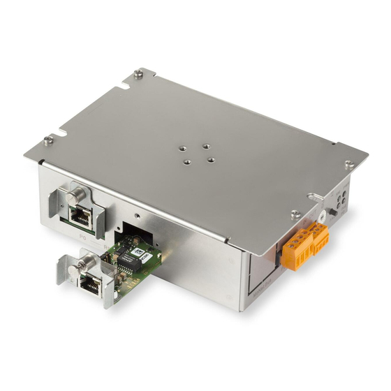
- Page 1 FN2012-A1 Ethernet switch (modular) Installation Mounting Smart Infrastructure A6V10407862_e_en_-- 2019-11-25...
- Page 2 Issued by: Siemens Industry, Inc. Smart Infrastructure 8 Fernwood Road Florham Park, NJ 07932 Tel. +1 973-593-2600 www.sbt.siemens.com/FIS Edition: 2019-11-25 Document ID: A6V10407862_e_en_-- A5Q00060099 © Siemens Industry, Inc., 2015 2 | 32 A6V10407862_e_en_--...
-
Page 3: Table Of Contents
Table of contents Ethernet switch (modular) FN2012-A1 ............Description...................... Installation ...................... Installation in FS20/FS920 housing..............Installation in XLS housings ................Installation of the Ethernet modules ............... Views ......................Wiring ......................Wiring overview ....................General wiring FS20/FS920 ................General wiring XLS.................. - Page 4 4 | 32 A6V10407862_e_en_--...
-
Page 5: Ethernet Switch (Modular) Fn2012-A1
Ethernet switch (modular) FN2012-A1 Description 1 Ethernet switch (modular) FN2012-A1 1.1 Description The Ethernet switch (modular) FN2012 is intended exclusively for the operation of an Ethernet network for the physical connection to voice and VoIP components for use in fire detection. - Page 6 Ethernet switch (modular) FN2012-A1 Description ● 2x Ethernet ports for external Ethernet (increased EMC safety and ground fault supervision) ● MoNet bus connection for transmitting the peripheral data bus signal via connection module (MoNet) ● Configurable with 16-pin rotary switch ●...
-
Page 7: Installation
Installation Installation in FS20/FS920 housing 2 Installation 2.1 Installation in FS20/FS920 housing The Ethernet switch (modular) FN2012 can be installed in all FS20/FS920 housings (1HU and 2HU). The example below illustrates installation in a fire control panel in the housing (2HU). If the Ethernet switch (modular) is used as a repeater, it is installed as a separate component in an external housing (1HU). -
Page 8: Installation In Xls Housings
Installation Installation in XLS housings 3x fixing screw Fixing slot in side tab Threaded standoffs on back box 1. Position the Ethernet switch (2) as shown. 2. Inserting the 3 fastening screws (3) into the side tabs (4) and screw the Ethernet switch (2) to the threaded sleeves (5) in the back box (1). 3. -
Page 9: Installation Of The Ethernet Modules
Installation Installation of the Ethernet modules 2.3 Installation of the Ethernet modules The FN2012 can be equipped with Ethernet modules, depending on the application. All Ethernet modules are installed in the same way. Figure 3: Installing the Ethernet module in the FN2012 Ethernet switch (modular) FN2012 Ethernet module installed Fastening screw with retention spring... - Page 10 Installation Installation of the Ethernet modules 1. Position the Ethernet module (4) as shown. 2. Slide the Ethernet module (4) into the opening of the option slot so that the plug contacts (5) slot into the Ethernet switch plug connector. 3. Make sure that the Ethernet module (4) slots into the positioning aids (7). 4.
-
Page 11: Views
Views 3 Views Figure 4: View of controls and indicators FN2012 Key for the operation and indication elements Element Des. Function Connector POWER X301 plug connection for external supply in the same housing or room FAULT X302 connector strip for fault signals: ●... - Page 12 Views Key for the Ethernet connections Element Des. Function Connector Internal Ethernet connection 1 (LOCAL), limited to the same housing Internal Ethernet connection 2 (LOCAL), limited to the same housing External Ethernet connection 1 (FIELD), limited to the same housing or the same room up to a maximum length of 20 ft/6 m External Ethernet connection 2 (FIELD), limited to the same housing or the same room up to a maximum length of 20 ft/6 m...
-
Page 13: Wiring
Wiring Wiring overview 4 Wiring 4.1 Wiring overview The figure shows a typical application of the Ethernet switch built into an FS20 panel as well as all connections. The example shows the wiring of a panel in an optical Ethernet ring. Ethernet Ring MoNet 2x Ethernet external... -
Page 14: General Wiring Fs20/Fs920
Not used Panel Approved Siemens panel in which the Ethernet switch (modular) is being installed The electrical Ethernet cable for connections P2...P5, as well as the connections via the Ethernet module (electric) VN2001 to connections P0 and P1 must be at least 6 ft/2 m long. -
Page 15: General Wiring Xls
Wiring General wiring XLS 4.3 General wiring XLS non power limited DC 24 V OUT P4/P5 POWER local Ethernet A+, A- Figure 9: Wiring overview of XLS components ● The Ethernet switch (modular) is supplied via the PSC-12 power supply, connection TB4. -
Page 16: Ethernet Switch In The Ethernet Network
Wiring Ethernet switch in the Ethernet network Ribbon cable connection for MoNet bus Figure 11: Connecting the MoNet bus ribbon cable Connect the 1.35 m/4.43 ft long ribbon cable for the MoNet bus as shown on the Ethernet switch (modular). 4.5 Ethernet switch in the Ethernet network The basic circuit diagram below shows the possible applications of the Ethernet switch in a redundant Ethernet ring network. - Page 17 Wiring Ethernet switch in the Ethernet network ● Electric Ethernet with copper wiring via 10/100BaseT connections (RJ-45 connector) with a VN2001 module – max. 330 ft/100 m long ● Optical Ethernet with a fiber-optic 100BaseFX connection in multi-mode version with a VN2002 module – max. 13100 ft/4 km long ●...
-
Page 18: Ethernet Switch As A Repeater
Wiring Ethernet switch as a repeater 4.6 Ethernet switch as a repeater The Ethernet switch (modular) can also be used as a repeater in the electric Ethernet. For each repeater, the distance of the electric Ethernet connection increases by 330 ft/100 m. The repeater is supplied with power via PoE from the installed Ethernet module (electric) VN2001. - Page 19 Wiring Ethernet switch as a repeater Two repeaters Ground fault PoE & Ground fault Electrical Ethernet Switch1 100 m 100 m 100 m Switch2 MoNet MoNet MoNet MoNet Repeater2 Repeater1 MoNet MoNet Ethernet Ethernet PMI & Mainboard PMI & Mainboard Panel Panel Figure 15: 2x Ethernet switch (modular) as a repeater in the electric Ethernet...
-
Page 20: Jumper Settings On The Vn2001
Jumper settings on the VN2001 5 Jumper settings on the VN2001 The slots the jumpers are plugged into on the Ethernet module (electric) differ depending on how the module will be used. The table below shows the different settings for the corresponding function. X102 Figure 16: View of VN2001 with jumper strip X102 jumper strip... - Page 21 Jumper settings on the VN2001 Jumper setting on X102 Function PoE for cables crossed at one end A6V10407862_e_en_-- 21 | 32...
-
Page 22: Pin Assignments
Pin assignments 'POWER' connector strip 6 Pin assignments 6.1 'POWER' connector strip The 'POWER' connector is only needed if the supply is not possible via the MoNetBus or PoE. This is generally only the case if the Ethernet switch (modular) is installed remotely in another device. - Page 23 Pin assignments 'POWER' connector strip Admissible cable cross-section: AWG 24...AWG 12 / 0.2...2.5 mm² F4 F3 F2 F1 Connector Terminal Plug Cover cap (open) A6V10407862_e_en_-- 23 | 32...
-
Page 24: Indicators
Indicators 7 Indicators Color Function Condition Meaning Green Power LED Lit up ● Normal operation Not lit up ● No power supply FAUL Yellow General fault See separate FAULT LED table Green Redundancy manager See separate RM LED table Green Not connected No function No function... - Page 25 Indicators Function indicator Possible troubleshooting steps Fatal FAULT ● Perform a reset. If that does not work, there is a hardware fault. ● Replace the Ethernet switch. Check whether any other fault messages are being displayed in the FS20 system. Table 3: Troubleshooting Function indicators for the RM LED (redundancy manager) Within each MRP ...
- Page 26 Indicators Function indicator Possible troubleshooting steps Ring open ● Check the MRP ring. There is a break in the ring at one or more of the panels. ● Check whether cable is defective. ● Ring port LEDs which are switched off show open ports –...
-
Page 27: Adjustment Elements
Adjustment elements 8 Adjustment elements Reset button The reset button has a number of functions depending on how long it is pressed for. RESET button pressed for … FAULT LED status Function/result <5 s Not lit up Hardware reset: The FN2012 is restarted immediately after pressing the reset button. - Page 28 Adjustment elements Switch position IP address/operating mode Sub-net mask/operating mode Repeater mode Repeater mode 192.168.200.4 255.255.255.0 28 | 32 A6V10407862_e_en_--...
-
Page 29: Technical Data
Technical data 9 Technical data Supply Operating voltage DC 24 V Standby power consumption 95 mA @24 V Built-in power consumption, supply via Max. 380 mA @ 24 V MoNetBus or AUX power Power consumption via PoE Max. 185 mA @ 24 V Ethernet interfaces Sockets 4x RJ45, 10/100 Mbit/s Length of line ●... - Page 30 Technical data Sample calculation ● Optical budget for VN2002: 11 dB ● Cable loss: 2.5 dB/3280 ft / 2.5 dB/km ● Male connector loss: 1.0 dB ● Transmission losses: 0.5 dB Length = (optical budget – 2x male connector loss – transmission losses) / (cable loss per km) Length in km = (11 dB – 2 x 1 dB – 0.5 dB) / 2.5 dB per km = 3.4 km Length in ft = (11 dB –...
-
Page 31: Fcc Statement
FCC Statement 10 FCC Statement WARNING Installation and usage of equipment is not in accordance with instructions manual Radiation of radio frequency energy Interference to radio communications ● Install and use equipment in accordance with instructions manual. ● Read the following information. This equipment generates, uses, and can radiate radio frequency energy and if not installed and used in accordance with the instructions manual, may cause interference to radio communications. - Page 32 © Siemens Industry, Inc., 2015 Issued by Siemens Industry, Inc. Technical specifications and availability subject to change without notice. Smart Infrastructure 8 Fernwood Road Florham Park, NJ 07932 +1 973-593-2600 www.sbt.siemens.com/FIS A6V10407862_e_en_--...