Table of Contents
Advertisement
Quick Links
Advertisement
Table of Contents

Related Manuals for Dell C5518QT


Summary of Contents for Dell C5518QT
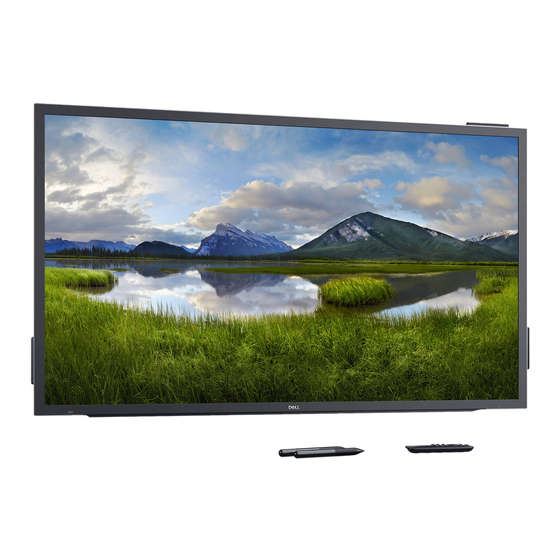
- Page 1 Dell C5518QT User’s Guide Model: C5518QT Regulatory model: C5518QTt...
- Page 2 WARNING: A WARNING indicates a potential for property damage, personal injury, or death. Copyright © 2017-2020 Dell Inc. or its subsidiaries. All rights reserved. Dell, EMC, and other trademarks are trademarks of Dell Inc. or its subsidiaries. Other trademarks may be trademarks of their respective owners. 2020-11...
-
Page 3: Table Of Contents
Using the On-Screen Display (OSD) Menu ....38 Dell Web Management for Displays ..... . . 52 Troubleshooting . - Page 4 FCC Notices (U.S. only) and Other Regulatory Information ..65 Contacting Dell ........65 EU product database for energy label and product information sheet .
-
Page 5: About Your Display
Package Contents Your display ships with the components shown below. Make sure that you have received all the components and contact Dell if something is missing. NOTE: Some items may be optional and may not ship with your display. Some features or media may not be available in certain countries. - Page 6 Stylus x 2 Stylus holder Wire Saddle x 3 Power cable (varies by country) Power cable for connecting Optiplex system to display (see Optiplex (Optional)) USB 3.0 upstream cable (enables the USB ports on the display) DP cable (DP to DP) VGA cable About Your Display...
- Page 7 HDMI cable • Safety, Environmental and Regulatory Information • DisplayNote License Key • Quick Setup Guide About Your Display...
-
Page 8: Product Features
Product Features The Dell C5518QT display has an active matrix, thin film transistor (TFT), liquid crystal display (LCD), and LED backlight. The display features include: • 138.78 cm (54.64-inch) active area display (Measured diagonally) 3840 x 2160 (16:9 aspect ratio) resolution, plus full-screen support for lower resolutions. -
Page 9: Identifying Parts And Controls
Identifying Parts and Controls Front view Label Description Screen drop down touch key IR Lens OSD Launcher touch key (For more information, see Operating the Display) Power on/off button (with LED indicator) Solid white light indicates the monitor is turned on and functioning normally. Blinking white light indicates the monitor is in Standby Mode. - Page 10 Back View Label Description Mounting provision for WR517 (optional For Dell Wireless Receiver : item) WR517(optional) Wire Saddle Use to handle display during installation Handle x 2 Use to move the display. VESA mounting holes (300 x 300 mm) To mount the display.
- Page 11 Side View Label Description HDMI 1 connector HDMI 2 connector Connect your computer with HDMI cable. HDMI 3 connector DP connector Connect your computer with DP cable. VGA connector Connect your computer with VGA cable. Audio line-in port Analog audio (two channel) input. Audio line-out port Connect to external audio peripherals.
- Page 12 USB Dedicated charging USB 3.0 with 12.5 W - For WR517 Wireless Receiver port (Optional) Power supply (5V/2.5A) RS232 connector Remote management and control of display via RS232 RJ-45 connector Remote Network Management and control of display via RJ-45 Input sources and USB pairing Input sources USB upstream HDMI 1...
-
Page 13: Display Specifications
Display Specifications Screen type Active matrix - TFT LCD Panel Type In-plane switching Technology Aspect ratio 16:9 Viewable image dimensions Diagonal 138.78 cm (54.64 inches) Active Area Horizontal 1209.6 mm (47.62 inches) Vertical 680.4 mm (26.79 inches) Area 823011.84 mm (1275.67 inches Pixel pitch 0.315 mm x 0.315 mm... - Page 14 Border width (edge of display to 26.9 mm (Top) active area) 26.9 mm (Left/Right) 26.9 mm (Bottom) Cable management Touch Type InGlass Touch Technology (TM) Input Method Bare finger and stylus Interface USB HID Compliant Touch Driver Windows driver installation for Windows 7 Up to 20 points touch Touch point Up to 4 pens...
- Page 15 >20 mm from active touch area edge >20 mm from active touch area edge Note that touch sensor input accuracy is defined relative to the active touch area as defined in the reference drawing (listed in 8.1). The overall system accuracy, of touch co-ordinates relative to display co-ordinates, is directly affected by integration assembly tolerances.
- Page 16 Electrical Specifications Video input signals • Digital video signal for each differential line Per differential line at 100 ohm impedance • DP/HDMI/VGA signal input support Input voltage/ frequency/current 100-240 VAC / 50 or 60 Hz ± 3 Hz / 4.5 A (maximum) Output voltage/ frequency/current 100-240 VAC / 50 or 60 Hz ±...
- Page 17 Physical Characteristics Connector type • DP connector • VGA connector • HDMI connector • Audio line-out • Audio line-in • USB 3.0 connector • USB Dedicated charging port- supplying power of up to 5 V (max 2.5A) for connected devices • RJ-45 • RS232 connector Signal cable type (in-box) DP, 3 m cable HDMI, 3 m cable VGA, 3 m cable...
- Page 18 Environmental Characteristics Compliant Standards ENERGY STAR certified Monitor EPEAT EPEAT registered where applicable. EPEAT registration varies by country. See www.epeat.net for registration status by country. RoHS Compliant Temperature Operating 0 °C to 40 °C (32 °F to 104 °F) Non-operating –20 °C to 60 °C (–4 °F to 140 °F) Humidity Operating...
- Page 19 Pin Assignments DP connector Pin number 20-pin side of the connected signal cable ML3(n) ML3(p) ML2(n) ML2(p) ML1(u) ML1(p) ML0(n) ML0(p) CONFIG1/(GND) CONFIG2/(GND) AUX CH (p) DP_Cable Detect AUX CH (n) Hot Plug Detect +3.3V DP_PWR About Your Display...
- Page 20 VGA connector Pin number 15-pin side of the connected signal cable Video-Red Video-Green Video-Blue Self-test GND-R GND-G GND-B Computer 5 V / 3.3 V GND-sync DDC data H-sync V-sync DDC clock About Your Display...
- Page 21 HDMI connector Pin number 19-pin side of the connected signal cable TMDS DATA 2+ TMDS DATA 2 SHIELD TMDS DATA 2- TMDS DATA 1+ TMDS DATA 1 SHIELD TMDS DATA 1- TMDS DATA 0+ TMDS DATA 0 SHIELD TMDS DATA 0- TMDS CLOCK+ TMDS CLOCK SHIELD TMDS CLOCK-...
- Page 22 RS232 connector Pin number 9-pin side of the connected signal cable Not Used Not Used About Your Display...
- Page 23 RJ-45 connector Pin number 12-pin side of the connected signal cable LED2_Y+ LED2_Y- LED2_G+ LED2_G- About Your Display...
- Page 24 Universal Serial Bus (USB) This section gives you information about the USB ports available on your display. Your computer has the following USB ports: • 3 USB 3.0 upstream • 3 USB 3.0 downstream • 1 USB Dedicated charging port Power supply port - the ports only for WR517 Wireless receiver Power supply (5V/2.5A).
-
Page 25: Plug-And-Play
During the LCD display manufacturing process, it is not uncommon for one or more pixels to become fixed in an unchanging state which are hard to see and do not affect the display quality or usability. For more information on LCD Display Pixel Policy, see Dell support site at: http:// www.dell.com/support/monitors. -
Page 26: Setting Up The Display
Setting Up the Display Connecting Your Display WARNING: Before you begin any of the procedures in this section, follow the Safety Instructions. To connect your display to the computer: 1. Turn off your computer. 2. Connect the HDMI/DP/VGA/USB cable from your display to the computer. 3. - Page 27 Connecting the HDMI cable Connecting the DP cable Connecting the VGA cable Setting Up the Display...
- Page 28 Optiplex (Optional) Attaching the Optiplex • Remove the Optiplex holder. Remove cable cover. Install Optiplex PC and power adapter into re- spective slot. Insert and organize the cables. • Slide Optiplex holder back into display. Setting Up the Display...
- Page 29 Connecting the Optiplex Connecting the HDMI cable Connecting the DP cable Setting Up the Display...
- Page 30 Connecting the VGA cable Setting Up the Display...
-
Page 31: Wall Mounting (Optional)
• Do not attempt to wall mount the Touch Display by yourself. it should be installed by qualified installers. • Recommended Wall Mount for this Display is can be found in the Dell support website at dell.com/support. NOTE: For use only with UL or CSA or GS-listed wall mount bracket with minimum weight/load bearing capacity of 53 kg (116.84 lb). -
Page 32: Remote Control
Remote Control 4. Left Press to move the selection left in OSD menu. 5. Down Press to move the selection down in OSD menu. 6. Menu Press to turn on the OSD menu. 7. Brightness - Press to decrease the Brightness. 8. - Page 33 Inserting the batteries in the remote control The remote control is powered by two 1.5V AAA batteries. To install or replace batteries: 1. Press and then slide the cover to open it. 2. Align the batteries according to the (+) and (–) indications inside the battery compartment.
- Page 34 Operating range of the remote control Point the top of the remote control toward the LCD display’s remote sensor during button opera- tion. Use the remote control within a distance of about 8 m from remote control sensor or at a hori- zontal and vertical angle of within 15°...
-
Page 35: Operating The Display
Operating the Display Turning on the Display Press the Power button to turn the display On and Off. The white LED indicates the display is On and fully functional. A glowing white LED indicates Standby Mode. Touch OSD Launcher This display comes with a touch OSD functionalities. Press the OSD launcher touch key to access the functionalities. -
Page 36: Using The Touch Control Launcher
Using the Touch Control Launcher Use the touch control icons on the front of the display to adjust the characteristics of the image being displayed. As you use these icons to adjust the controls, an OSD shows the numeric values of the characteristics as they change. -
Page 37: Using The Osd Lock Function
Using the OSD lock function 1. Press the OSD launcher touch key. 2. Touch and hold for 5 seconds. you can see following select option: The following table describes the touch control icons: Description Options Use this icon to lock OSD menu function. OSD menu lock Use this icon to lock power button from powering off. -
Page 38: Using The On-Screen Display (Osd) Menu
3. Touch and hold for 5 seconds, touch to unlock. NOTE: This OSD lock feature is available from firmware version M2T103 or later. Using the On-Screen Display (OSD) Menu Accessing the Menu System NOTE: Any changes you make using the OSD menu are automatically saved if you move to another OSD menu, exit the OSD menu, or wait for the OSD menu to disappear. - Page 39 Use the OK icon to confirm your selection. Use the Back icon to go back to the previous menu. Back Touch OSD Control Icon Menu and Description Submenus Brightness/ Use this menu to activate Brightness/Contrast adjustment. Contrast Brightness Brightness adjusts the luminance of the backlight (minimum 0;...
- Page 40 Icon Menu and Description Submenus Auto Adjust Even though your computer recognizes your display on startup, the Auto Adjustment function optimizes the display settings for use with your particular setup. Auto Adjustment allows the display to self-adjust to the incoming video signal.
- Page 41 Icon Menu and Description Submenus Input Source Use the Input Source menu to select between different video inputs that are be connected to your display. Select VGA input when you are using the VGA connector. Select DP input when you are using the DP (DisplayPort) connector. HDMI 1 Select the HDMI 1 input when you are using the HDMI 1 connector.
- Page 42 Icon Menu and Description Submenus Preset Modes When you select Preset Modes, you can choose Standard, ComfortView, Multimedia, Color Temp., or Custom Color from the list. • Standard: Default color settings. This is the default preset mode. • ComfortView: Decreases the level of blue light emitted from the screen to make viewing more comfortable for your eyes.
- Page 43 Icon Menu and Description Submenus Input Color Allows you to set the video input mode to: Format • RGB: Select this option if your display is connected to a computer (or DVD player) using the HDMI, DP or VGA cable. • YPbPr: Select this option if your DVD player supports only YPbPr output.
- Page 44 Icon Menu and Description Submenus Display Use the Display menu to adjust image. Aspect Ratio Adjust the image ratio to Wide 16:9, Auto Resize,4:3, or 5:4. Horizontal to adjust the image left or right. Position Minimum is ‘0’ (-). Maximum is ‘100’ (+). Vertical to adjust the image up or down.
- Page 45 Icon Menu and Description Submenus Reset Display Restores the display settings to factory defaults. Audio Volume Allows you to set the volume level of audio source. to adjust the volume level from ‘0’ to ‘100’. Audio Source Allows you to set the audio source to PC Audio or HDMI/DP.
- Page 46 Icon Menu and Description Submenus Language Set the OSD display to one of eight languages. (English, Spanish, French, German, Brazilian Portuguese, Russian, Simplified Chinese, or Japanese). Transparency Select this option to change the menu transparency by using icons (min. 0 / max. 100). Timer OSD Hold Time: Sets the time the OSD remains active after you press a button.
- Page 47 Icon Menu and Description Submenus Screen Off Allows you to set the Screen Off Color to White or black. Color Wake On Select Enable to turn on this feature. Touch Reset Restores shortcut keys to factory defaults. Persona- lization Other Select this option to adjust the OSD settings, such as the DDC/CI, LCD conditioning, and so on.
- Page 48 Icon Menu and Description Submenus Helps reduce minor cases of image retention. Depending on the Conditioning degree of image retention, the program may take some time to run. Select Enable to start the process. Firmware Current Firmware version. IP Address Show IP Address.
- Page 49 OSD Warning Messages When the display does not support a particular resolution mode, you can see the following message: This means that the display cannot synchronize with the signal that it is receiving from the computer. See Display Specifications for the Horizontal and Vertical frequency ranges addressable by this display.
- Page 50 If you press any button other than the power button, the following messages will appear depending on the selected input: If either HDMI 1, HDMI 2, HDMI 3, DP or VGA input is selected and the corresponding cable is not connected, a floating dialog box as shown below appears. Operating the Display...
- Page 51 Select OSD items of On in Standby Mode in Personalize feature, the following message will appear: If adjust the Brightness level above the default level over 75%, the following message will appear: Troubleshooting for more information. Operating the Display...
-
Page 52: Dell Web Management For Displays
Touch and hold the touch key 5 on the front panel for 4 seconds to turn off , A network icon appears and is shown on the center for 4 seconds. To access the Dell Display Web Management tool you need to set the IP Addresses for your computer and the display. - Page 53 2. In the computer’s IP Properties tab, specify an IP Address by selecting Use the following IP Address and enter the following values: For IP Address: 10.0.50.101 and for Subnet Mask: 255.0.0.0 (leave all other entries as blanks). 3. The IP Address configuration would now look like this: To access and use the web management tool, follow these steps: 1.
- Page 54 3. The Home page opens: 4. Click Network Settings tab to see the network settings. Operating the Display...
- Page 55 5. Click Display Control to see the display’s status. 6. Update Firmware. You can download the latest drivers from the Dell Support website at www.dell.com/support. 7. Upgrade firmware page and wait for 30 seconds. Operating the Display...
- Page 56 8. Finished. Click on button to proceed after 8 seconds. 9. Click Security to set a password. 10. Click Crestron to control interface. Operating the Display...
-
Page 57: Troubleshooting
Troubleshooting WARNING: Before you begin any of the procedures in this section, follow the Safety Instructions. Self-Test Your display provides a self-test feature that allows you to check whether your display is functioning properly. If your display and computer are properly connected but the display screen remains dark, run the display self-test by performing the following steps: 1. - Page 58 4. This box also appears during normal system operation, if the video cable becomes disconnected or damaged. 5. Turn off your display and reconnect the video cable; then turn on both your computer and the display. If your display screen remains blank after you use the previous procedure, check your video controller and computer, because your display is functioning properly.
-
Page 59: Built-In Diagnostics
Built-in Diagnostics Your display has a built-in diagnostic tool that helps you determine if the screen abnormality you are experiencing is an inherent problem with your display, or with your computer and video card. To run the built-in diagnostics: 1. Make sure that the screen is clean (no dust particles on the surface of the screen). 2. -
Page 60: Common Problems
• Relocate the display and test in another room. Missing Pixels LCD screen has • Cycle power on-off. spots • Pixel that is permanently off is a natural defect that can occur in LCD technology. • For more information on Dell Display Quality and Pixel Policy, see Dell Support site at: http://www.dell.com/support/monitors. Stuck-on Pixels LCD screen has • Cycle power On-Off. bright spots • Pixel that is permanently off is a natural defect that can occur in LCD technology. - Page 61 • Restart the computer in safe mode. Safety Related Visible signs of • Do not perform any troubleshooting steps. Issues smoke or sparks • Contact Dell immediately. Intermittent Display • Ensure that the video cable connecting the display to Problems malfunctions on the computer is connected properly and is secure.
-
Page 62: Product Specific Problems
Common What You Possible Solutions Symptoms Experience Image retention Faint shadow • Set the screen to turn off after a few minutes of from a static from the static screen idle time. These can be adjusted in Windows image left on the image displayed Power Options or Mac Energy Saver setting. -
Page 63: Touchscreen Problems
Specific What You Possible Solutions Symptoms Experience Cursor does not accurately follow • Install touch driver for Windows 7, see Dell Support Windows 7 your finger when site at: http://www.dell.com/support/monitors. you touch the screen Universal Serial Bus (USB) Specific Problems... -
Page 64: Ethernet Problems
Ethernet Problems Specific What You Possible Solutions Symptoms Experience Ethernet not Dell Web • Ensure that the Network cable connecting the Display working Management for is properly secured. Displays Webpage • Touch the icon 5 on the screen for 4 seconds to turn... -
Page 65: Appendix
For customers in the United States, call 800-WWW-DELL (800-999-3355). NOTE: If you do not have an active Internet connection, you can find contact information on your purchase invoice, packing slip, bill, or Dell product catalog. Dell provides several online and telephone-based support and service options. Availability varies by country and product, and some services may not be available in your area. -
Page 66: Setting Up Your Display
2. After installing the drivers for your graphics adapter, attempt to set the resolution to 3840 x 2160 again. NOTE: If you are unable to set the resolution to 3840 x 2160, please contact Dell to inquire about a graphics adapter that supports these resolutions. - Page 67 Non-Dell computer In Windows 7, Windows 8 or Windows 8.1: 1. For Windows 8 or Windows 8.1 only, select the Desktop tile to switch to classic desktop. 2. Right-click on the desktop and click Personalization. 3. Click Change Display Settings.
-
Page 68: Maintenance Guidelines
Maintenance Guidelines Cleaning Your Display WARNING: Before cleaning the display, unplug the display power cable from the electrical outlet. CAUTION: Read and follow the Safety Instructions before cleaning the display. For best practices, follow these instructions in the list below while unpacking, cleaning, or handling your display: • To clean your anti-static screen, lightly dampen a soft, clean cloth with water.