ABB ACS880-11 Hardware Manual
Hide thumbs
Also See for ACS880-11:
- Hardware manual (230 pages) ,
- Manual (52 pages) ,
- Firmware manual (604 pages)
Table of Contents
Advertisement
Advertisement
Table of Contents

Related Manuals for ABB ACS880-11


Summary of Contents for ABB ACS880-11
- Page 1 — ABB INDUSTRIAL DRIVES ACS880-11 drives Hardware manual...
- Page 3 ACS880-11 drives Hardware manual Table of contents 1. Safety instructions 4. Mechanical installation 6. Electrical installation – IEC 7. Electrical installation – North America (NEC) 10. Start-up 3AXD50000045932 Rev F Original instructions EFFECTIVE: 2021-07-15...
-
Page 5: Table Of Contents
Table of contents 5 Table of contents 1 Safety instructions Contents of this chapter ..................Use of warnings and notes ................. General safety in installation, start-up and maintenance ........Electrical safety in installation, start-up and maintenance ........Electrical safety precautions ................ Additional instructions and notes .............. - Page 6 Availability of du/dt filter and common mode filter by drive type ..Additional requirements for explosion-safe (EX) motors ....Additional requirements for ABB motors of types other than M2_, M3_, M4_, HX_ and AM_ ..............Additional requirements for the regenerative and low harmonics drives ....................
- Page 7 Table of contents 7 Power cable types ..................Preferred power cable types ............. Alternate power cable types ............. Not allowed power cable types ............Additional guidelines, North America ............Metal conduit ..................Power cable shield ..................Selecting the control cables ................Shielding ......................
- Page 8 8 Table of contents 6 Electrical installation – IEC Contents of this chapter ..................Safety ........................Required tools ..................... Grounding the motor cable shield at the motor end ..........Measuring the insulation ..................Measuring the insulation resistance of the drive .......... Measuring the insulation resistance of the input power cable .....
- Page 9 Table of contents 9 Required tools ..................... Measuring the insulation ..................Grounding system compatibility check ............... Connecting the power cables ................Connection diagram ..................Connection procedure .................. R8 power cable connection if you detach the connectors ....Connecting the control cables ................Connection diagram ..................
- Page 10 Calculating the short-circuit current of the installation ......... Calculation example ................. Fuses (UL) ......................Circuit breakers (IEC) ..................Circuit breakers (UL) ................... ABB inverse time circuit breakers ..............Dimensions, weights and free space requirements ..........Free space requirements ................Package dimensions ..................
- Page 11 Table of contents 11 Losses, cooling data and noise ................IEC ....................... UL (NEC) ...................... Cooling air flow and heat dissipation for flange mounting (option +C135) ..Terminal and entry data for the power cables ............. UL listed cable lugs and tools ..............Terminal and entry data for the control cables ............
- Page 12 12 Table of contents Description ......................Compliance with the European Machinery Directive and the UK Supply of Machinery (Safety) Regulations ..............Wiring ........................Activation switch ................... Cable types and lengths ................Grounding of protective shields ..............Single drive (internal power supply) ............. Multiple drives ....................
-
Page 13: Safety Instructions
Safety instructions 13 Safety instructions Contents of this chapter This chapter contains the safety instructions which you must obey when you install, start-up, operate and do maintenance work on the drive. If you ignore the safety instructions, injury, death or damage can occur. Use of warnings and notes Warnings tell you about conditions which can cause injury or death, or damage to the equipment. -
Page 14: General Safety In Installation, Start-Up And Maintenance
14 Safety instructions General safety in installation, start-up and maintenance These instructions are for all personnel who do work on the drive. WARNING! Obey these instructions. If you ignore them, injury or death, or damage to the equipment can occur. •... -
Page 15: Electrical Safety In Installation, Start-Up And Maintenance
Safety instructions 15 • Before you adjust the drive operation limits, make sure that the motor and all driven equipment can operate throughout the set operation limits. • Before you activate the automatic fault reset or automatic restart functions of the drive control program, make sure that no dangerous situations can occur. -
Page 16: Additional Instructions And Notes
16 Safety instructions Go through these steps before you begin any installation or maintenance work. 1. Clearly identify the work location and equipment. 2. Disconnect all possible voltage sources. Make sure that re-connection is not possible. Lock out and tag out. •... -
Page 17: Printed Circuit Boards
Safety instructions 17 • Make sure that the electrical power network, motor/generator, and environmental conditions agree with the drive data. • Do not do insulation or voltage withstand tests on the drive. • If you have a cardiac pacemaker or other electronic medical device, keep away from the area near motor, drive, and the drive power cabling when the drive is in operation. - Page 18 18 Safety instructions • Make a 360° grounding of the power and control cable shields at the cable entries to suppress electromagnetic disturbances. • In a multiple-drive installation, connect each drive separately to the protective earth (PE) busbar of the power supply. Note: •...
-
Page 19: General Safety In Operation
Safety instructions 19 General safety in operation These instructions are for all personnel that operate the drive. WARNING! Obey these instructions. If you ignore them, injury or death, or damage to the equipment can occur. • If you have a cardiac pacemaker or other electronic medical device, keep away from the area near motor, drive, and the drive power cabling when the drive is in operation. -
Page 20: Safety In Operation
20 Safety instructions • Do not do work on the drive when a rotating permanent magnet motor is connected to it. A rotating permanent magnet motor energizes the drive including its input and output power terminals. Before installation, start-up and maintenance work on the drive: •... -
Page 21: Introduction To The Manual
Introduction to the manual 21 Introduction to the manual Contents of this chapter This chapter describes the intended audience and contents of the manual. It contains a flowchart of steps in examining the delivery, installing and commissioning the drive. The flowchart refers to chapters/sections in this manual and other manuals. Target audience This manual is intended for people who plan the installation, install, start-up and do maintenance work on the drive, or create instructions for the end user of the drive... - Page 22 22 Introduction to the manual Task Plan the electrical installation and acquire the accessories Guidelines for planning the electrical needed (cables, fuses, etc.). installation (page 53) Check the ratings, required cooling air flow, input power Technical data (page 161) connection, compatibility of the motor, motor connection, and other technical data.
-
Page 23: Terms And Abbreviations
Introduction to the manual 23 Task Firmware manual Commission the drive. Quick start-up guide for the drive Terms and abbreviations Term Description ACS-AP-I Industrial assistant non-Bluetooth control panel ACS-AP-W Industrial assistant control panel with Bluetooth interface Control unit The part in which the control program runs. DC link DC circuit between rectifier and inverter DC link capacitors... -
Page 24: Related Documents
3AXD50000181506 ACQ580-31…+C135 frame R3 flange mounting kit quick installation guide ACS880-11…+C135, ACS880-31…+C135, ACH580- 3AXD50000133611 31…+C135 and ACQ580-31…+C135 frames R6 and R8 flange mounting kit quick installation guide Common mode filter kit for ACS880-01, ACS880-11 and 3AXD50000015178 ACS880-31 drives installation instructions... - Page 25 Code (Transla- lish/Multilingual) tion) Common mode filter kit for ACS880-01 frame R7, and for 3AXD50000015179 ACS880-11, ACS880-31, ACH580-31 and ACQ580-31 frame R8 (option +E208) installation instructions 3AUA0000127818 Common DC systems with ACS880-01, -04, -11, -14, -31 and -34 rives application guide...
-
Page 27: Operation Principle And Hardware Description
Operation principle and hardware description 27 Operation principle and hardware description Contents of this chapter This chapter briefly describes the operation principle and construction of the drive. -
Page 28: Operation Principle
28 Operation principle and hardware description Operation principle The ACS880-11 is a four-quadrant drive for controlling asynchronous AC induction motors, AC induction servomotors, permanent magnet motors and synchronous reluctance motors. The drive includes a line-side converter and a motor-side converter. The parameters and signals for both converters are combined into one primary user program. -
Page 29: Dc Voltage Boost Function
• possibility to use a motor with higher nominal voltage than the actual supply voltage of the drive. Example: A drive that is connected to 415 V can supply 460 V to a 460 V motor. For more information, see ACS880-11, ACS880-31, ACS880-14, ACS880-34, ACS880-17, ACS880-37 drives product note on DC voltage boost (3AXD50000691838 [English]). -
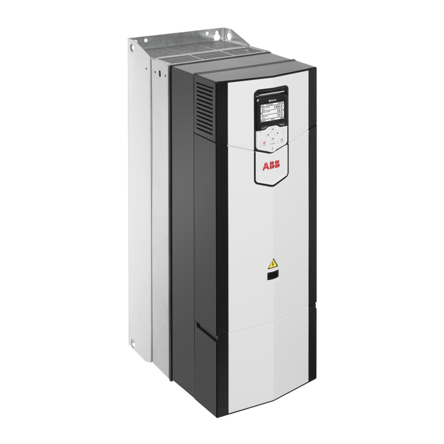
Page 30: Layout
30 Operation principle and hardware description Layout The layout of the drive is shown below. IP21 (UL Type 1) R6 IP55 (UL Type 12) option +B056, R6 UL Type 12 (R6) IP20 (UL Open Type) option +P940 R8 Lifting eyes (2 pcs in frame R3, 6 pcs in Front cover frames R6 and R8) Control panel... - Page 31 Operation principle and hardware description 31 14 15 16 Auxiliary cooling fan. For frame R3 in IP55 Clamps for securing the control cables (UL Type 12 drives) only. mechanically Clamps for securing the FSO wiring Input power cable entry behind the 360- mechanically degree grounding clamps Power cable connection terminals behind...
-
Page 32: Overview Of Power And Control Connections
32 Operation principle and hardware description Overview of power and control connections The logical diagram below shows the power connections and control interfaces of the drive. Slot 1 X208 Slot 2 Slot 3 U/T1 V/T2 W/T3 UDC+ UDC- Analog and digital I/O extension modules, feedback interface modules and fieldbus com- munication modules can be inserted into slots 1, 2 and 3. -
Page 33: Control Panel
Operation principle and hardware description 33 Control panel To remove the control panel, press the retaining clip at the top (1a) and pull the panel forward from the top edge (1b). To reinstall the control panel, put the bottom of the container in position (2a), press the retaining clip at the top (2b) and push the control panel in at the top edge (2c). -
Page 34: Control Panel Door Mounting Kits
34 Operation principle and hardware description ■ Control panel door mounting kits You can use a mounting platform to mount the control panel on the cabinet door. Mounting platforms for control panels are available as options from ABB. For more information, see Manual Code (English) -
Page 35: Type Designation Label
You find the type designation on the type designation label attached to the drive. The first digits from the left express the basic configuration, for example, ACS880-11-025A-3. The optional selections are given after that, separated by plus signs, for example, +K454. The main selections are described below. Not all selections... -
Page 36: Basic Code
36 Operation principle and hardware description ■ Basic code Code Description ACS880 Product series Type Regenerative wall-mounted drive. When no options are selected: IP21 (UL type 1), cable entry from bottom, ACS-AP-W Assistant control panel with a bluetooth interface, no EMC filter, ASC880 primary control program, Safe torque-off, coated boards, quick installation and start-up guide. - Page 37 Operation principle and hardware description 37 Code Description K462 FCNA-01 ControlNet™ adapter module K469 FECA-01 EtherCat adapter module K470 FEPL-02 EtherPOWERLINK adapter module FENA-21 Ethernet adapter module for EtherNet/IP™, Modbus TCP and PROFINET K475 IO protocols, 2-port K490 FEIP-21 EtherNet/IP adapter module K491 FMBT-21 Modbus/TCP adapter module K492...
- Page 38 38 Operation principle and hardware description Code Description R702 Italian R703 Dutch R704 Danish R705 Swedish R706 Finnish R707 French R708 Spanish R709 Portuguese R711 Russian R712 Chinese R714 Turkish...
-
Page 39: Mechanical Installation
(3AUA0000107668 [English]). Flange mounting (option +C135) See also: Manual name Code (English) ACS880-11…, ACS880-31…, ACH580-31… and ACQ580-31…+C135 3AXD50000349838 drives with flange mounting kit supplement 3AXD50000181506 ACS880-11…, ACS880-31…, ACH580-31… and ACQ580-31…+C135 frame R3 flange mounting kit quick installation guide ACS880-11…+C135, ACS880-31…+C135, ACH580-31…+C135 and 3AXD50000133611 ACQ580-31…+C135 frames R6 and R8 flange mounting kit quick install-... -
Page 40: Safety
40 Mechanical installation Safety WARNING! Frames R6 and R8: Lift the drive with a lifting device. Use the lifting eyes of the drive. Do not tilt the module. The drive is heavy and its center of gravity is high. An overturning drive can cause physical injury. Examining the installation site Examine the installation site. - Page 41 Mechanical installation 41 • vertically side by side • horizontally alone, IP21 (UL Type 1) only. Note: The vibration specification in the technical data may not be fulfilled. Note: IP21 (UL Type 1) construction only meets IP20 (UL Type Open) in horizontal orientation.
-
Page 42: Required Tools
42 Mechanical installation 200 mm (7.87 in.) 120 mm (4.72 in.) 250 mm (9.84 in.) 120 mm (4.72 in.) 300 mm (11.81 in.) Required tools To install the drive mechanically, you need the following tools: • drill with suitable bits •... -
Page 43: Moving The Drive
Mechanical installation 43 Moving the drive Move the drive in its transport package to the installation site. Use a pallet truck when you move a heavy drive package. Unpacking and examining delivery The figure below shows the drive package with its contents. Examine that all items are present and there are no signs of damage. - Page 44 44 Mechanical installation R3 IP21 (UL Type 1) and IP55 (UL Type 12) AXD50000664825 Control panel Package cushion Mounting template Foam cushion Package straps Cardboard tray I/O option module Cardboard sleeve Fieldbus option module Cardboard Box which contains control panel box 1 and option boxes 4 and 5 Printed quick guides and manuals, multi- Drive lingual residual voltage warning sticker,...
- Page 45 Mechanical installation 45 R6 IP21 (UL Type 1) 3AXD50000038252 Printed quick guides and manuals, multi- Drive with factory installed options lingual residual voltage warning sticker, manuals CD Accessories Outer box Mounting template Pallet Package straps VCI bag Plastic bag To unpack: •...
- Page 46 46 Mechanical installation R6 IP55 (UL Type 12) 3AXD50000038252 Printed quick guides and manuals, multi- Drive with factory installed options lingual residual voltage warning sticker, manuals CD Accessories Outer box Bubble wrap Cardboard insert Mounting template Pallet Package straps VCI bag Plastic bag UL Type 12 hood To unpack:...
- Page 47 Mechanical installation 47 R8 IP21 (UL Type 1) 3AXD50000106974 Printed quick guides and manuals, multi- Cardboard sleeve lingual residual voltage warning sticker, manuals CD VCI bag Plywood support Mounting template Pallet Package straps Screw Plastic bag Screw Packing bracket Drive with factory installed options Tray Common mode filter (option +E208) To unpack:...
- Page 48 48 Mechanical installation R8 IP55 (UL Type 12) 3AXD50000106974 Printed quick guides and manuals, multi- Cardboard sleeve lingual residual voltage warning sticker, manuals CD VCI bag (not included) Bubble wrap Plywood support Mounting template Pallet Package straps UL Type 12 hood Plastic bag Drive with factory installed options Packing bracket...
-
Page 49: Installing The Drive Vertically
Mechanical installation 49 Installing the drive vertically 1. Mark the hole locations using the mounting template included in the package. Do not leave the mounting template under the drive. The drive dimensions and hole locations are also shown in the dimension drawings. 2. - Page 50 50 Mechanical installation R3: M5 (#10) R6: M8 (5/16 ) R8: M8 (5/16 ) 18.7 29.6 37.2 10.3 IP21, UL Type 1 21.3 46.97 61.0 134.51 246.96 IP55, UL Type 12 23.3 51.38 138.92 260.19...
-
Page 51: Installing The Drive Vertically Side By Side
Mechanical installation 51 Installing the drive vertically side by side Drives can be installed side by side. Follow the steps in section Installing the drive vertically (page 49). Installing the drive horizontally The drive can be installed either the left or right side up. Follow the steps in section Installing the drive vertically (page 49). -
Page 53: Guidelines For Planning The Electrical Installation
ABB does not assume any liability whatsoever for any installation which breaches the local laws and/or other regulations. Furthermore, if the recommendations given by ABB are not followed, the drive may experience problems that the warranty does not cover. -
Page 54: European Union And United Kingdom
54 Guidelines for planning the electrical installation European Union and United Kingdom To meet the European Union Directives and United Kingdom Regulations, according to standard EN 60204-1, Safety of Machinery, the disconnecting device must be one of the following types: •... -
Page 55: North America
Examining the compatibility of the motor and drive Use asynchronous AC induction motors, permanent magnet synchronous motors, AC induction servomotors or ABB synchronous reluctance motors (SynRM motors) with the drive. Select the motor size and drive type from the rating table on basis of the AC line voltage and motor load. -
Page 56: Requirements Table
56 Guidelines for planning the electrical installation ■ Requirements table These tables show how to select the motor insulation system and when a drive du/dt and common mode filters and insulated N-end (non-drive end) motor bearings are required. Ignoring the requirements or improper installation may shorten motor life or damage the motor bearings and voids the warranty. - Page 57 Guidelines for planning the electrical installation 57 This table shows the requirements when an ABB motor is in use. Motor type Nominal AC line Requirement for voltage Motor insu- ABB du/dt and common mode filters, in- lation sys- sulated N-end motor bearings P n <...
- Page 58 58 Guidelines for planning the electrical installation This table shows the requirements when a non-ABB motor is in use. Motor type Nominal AC line Requirement for voltage Motor insu- ABB du/dt and common mode filters, in- lation sys- sulated N-end motor bearings P n <...
-
Page 59: Availability Of Du/Dt Filter And Common Mode Filter By Drive Type
If you will use an explosion-safe (EX) motor, follow the rules in the requirements table above. In addition, consult the motor manufacturer for any further requirements. Additional requirements for ABB motors of types other than M2_, M3_, M4_, HX_ and AM_ Use the selection criteria given for non-ABB motors. -
Page 60: Additional Requirements For Non-Abb High-Output And Ip23 Motors
The rated output power of high-output motors is higher than what is stated for the particular frame size in EN 50347 (2001). If you plan to use a non-ABB high-output motor or an IP23 motor, consider these additional requirements for protecting the motor insulation and bearings in drive systems: •... -
Page 61: Additional Data For Calculating The Rise Time And The Peak Line-To-Line Voltage
Guidelines for planning the electrical installation 61 Nominal AC supply Requirement for voltage Motor insulation sys- ABB du/dt and common mode filters, insu- lated N-end motor bearings P n < 100 kW or frame 100 kW < P n < 350 kW size < IEC 315 IEC 315 <... - Page 62 62 Guidelines for planning the electrical installation Û du/dt ------------ - (1/μs) l (m) du/dt ------------ - (1/μs) Û l (m) Drive with du/dt filter Drive without du/dt filter Motor cable length Relative peak line-to-line voltage Û LL /U N (du/dt)/U N Relative du/dt value Note: Û...
-
Page 63: Additional Note For Sine Filters
Guidelines for planning the electrical installation 63 Additional note for sine filters A sine filter also protects the motor insulation system. The peak phase-to-phase voltage with a sine filter is approximately 1.5 · U Selecting the AC power cables ■ General guidelines Select the input power and motor cables according to local regulations. -
Page 64: Typical Power Cable Sizes
64 Guidelines for planning the electrical installation manner which produces a conductance equivalent to that which results from the application of this table. Cross-sectional area of the phase conduct- Minimum cross-sectional area of the corres- ponding protective conductor S (mm 2 ) S p (mm 2 ) S ≤... -
Page 65: Alternate Power Cable Types
Guidelines for planning the electrical installation 65 Cable type Use as input power cabling Use as motor cabling Symmetrical shielded (or ar- mored) cable with three phase conductors and symmetrically constructed PE conductor and a shield (or armor) Symmetrical shielded (or ar- mored) cable with three phase conductors and a shield (or ar- mor), and separate PE conduct-... -
Page 66: Not Allowed Power Cable Types
66 Guidelines for planning the electrical installation Cable type Use as input power cabling Use as motor cabling Yes with motors up to 100 kW (135 hp). A potential equaliza- tion between the frames of mo- tor and driven equipment is re- quired. -
Page 67: Additional Guidelines, North America
■ Additional guidelines, North America ABB recommends the use of conduit for power wiring to the drive and between the drive and the motor(s). Due to the variety of application needs, metallic and non-metallic conduit can be used. ABB recommends the use of metallic conduit. -
Page 68: Power Cable Shield
68 Guidelines for planning the electrical installation resistor, and control wiring. Do not run motor wiring from more than one drive in the same conduit. ■ Power cable shield If the cable shield is used as the sole protective earth (PE) conductor, make sure that its conductivity agrees with the PE conductor requirements. -
Page 69: Signals In Separate Cables
■ Relay cable The cable type with braided metallic shield (for example ÖLFLEX by LAPPKABEL, Germany) has been tested and approved by ABB. ■ Control panel to drive cable Use EIA-485 with male RJ-45 connector, cable type Cat 5e or better. The maximum permitted length of the cable is 100 m (328 ft). -
Page 70: General Guidelines - North America
70 Guidelines for planning the electrical installation • Where control cables must cross power cables, make sure that they are arranged at an angle as near to 90 degrees as possible. • Do not run extra cables through the drive. •... -
Page 71: Continuous Motor Cable Shield/Conduit Or Enclosure For Equipment On The Motor Cable
Guidelines for planning the electrical installation 71 Input power cabling Motor cabling Conduit ■ Continuous motor cable shield/conduit or enclosure for equipment on the motor cable To minimize the emission level when safety switches, contactors, connection boxes or similar equipment are installed on the motor cable between the drive and the motor: •... -
Page 72: Separate Control Cable Ducts
• possibility to use a motor with higher nominal voltage than the actual supply voltage of the drive. Example: A drive that is connected to 415 V can supply 460 V to a 460 V motor. For more information, see ACS880-11, ACS880-31, ACS880-14, ACS880-34, ACS880-17, ACS880-37 drives product note on DC voltage boost (3AXD50000691838 [English]). -
Page 73: Circuit Breakers
Guidelines for planning the electrical installation 73 Size the fuses or circuit breakers according to local regulations for the input cable protection. Select the fuses or circuit breakers for the drive according to the instructions given in the technical data. The fuses for the drive protection will restrict drive damage and prevent damage to adjoining equipment in case of a short-circuit inside the drive. -
Page 74: Protecting The Motor Against Thermal Overload
74 Guidelines for planning the electrical installation North America: The local code (NEC) requires an overload protection and a short-circuit protection for each motor circuit. Use, for example: • a manual motor protector • circuit breaker, contactor and overload relay or •... -
Page 75: Implementing A Motor Temperature Sensor Connection
Guidelines for planning the electrical installation 75 Implementing a motor temperature sensor connection WARNING! IEC 61800-5-1 requires double or reinforced insulation between live parts and accessible parts when: • the accessible parts are not conductive, or • the accessible parts are conductive, but not connected to the protective earth. Obey this requirement when you plan the connection of the motor temperature sensor to the drive. -
Page 76: Connecting Motor Temperature Sensor To The Drive Via An Option Module
76 Guidelines for planning the electrical installation ■ Connecting motor temperature sensor to the drive via an option module This table shows: • option module types that you can use for the motor temperature sensor connection • insulation or isolation level that each option module forms between its temperature sensor connector and other connectors •... -
Page 77: Implementing The Emergency Stop Function
Guidelines for planning the electrical installation 77 Note: As standard, the drive contains capacitors connected between the main circuit and the frame. These capacitors and long motor cables increase the ground leakage current and may cause nuisance faults in residual current devices. Implementing the emergency stop function For safety reasons, install the emergency stop devices at each operator control station and at other operating stations where emergency stop may be needed. -
Page 78: Implementing The Functions Provided By The Fso-Xx Safety Functions Module
78 Guidelines for planning the electrical installation Implementing the functions provided by the FSO-xx safety functions module You can order the drive with an FSO-12 or FSO-21 safety functions module (option +Q972 or +Q973) which enables the implementation of functions such as Safe brake control (SBC), Safe stop 1 (SS1), Safe stop emergency (SSE), Safely limited speed (SLS) and Safe maximum speed (SMS). -
Page 79: Using A Safety Switch Between The Drive And The Motor
Guidelines for planning the electrical installation 79 Using a safety switch between the drive and the motor ABB recommends to install a safety switch between the permanent magnet motor and the drive output. The switch is needed to isolate the motor from the drive during maintenance work on the drive. -
Page 80: Implementing A Bypass Connection
80 Guidelines for planning the electrical installation WARNING! When the DTC motor control mode is in use, never open the output contactor while the drive controls the motor. The DTC motor control operates extremely fast, much faster than it takes for the contactor to open its contacts. When the contactor starts opening while the drive controls the motor, the DTC control will try to maintain the load current by immediately increasing the drive output voltage to the maximum. - Page 81 Guidelines for planning the electrical installation 81 230 V AC 230 V AC + 24 V DC Relay output Varistor RC filter Diode...
-
Page 83: Electrical Installation - Iec
Electrical installation – IEC 83 Electrical installation – IEC Contents of this chapter This chapter gives instructions on wiring the drive. Safety WARNING! If you are not a qualified electrical professional, do not do installation or maintenance work. Obey the safety instructions of the drive. If you ignore them, injury or death, or damage to the equipment can occur. -
Page 84: Measuring The Insulation
Use a measuring voltage of 1000 V DC. The insulation resistance of an ABB motor must be more than 100 Mohm (reference value at 25 °C [77 °F]). For the insulation resistance of other motors, refer to the manufacturer’s instructions. -
Page 85: Grounding System Compatibility Check
Electrical installation – IEC 85 U1-PE, V1-PE, W1-PE 1000 V DC, > 100 Mohm Grounding system compatibility check The standard drive can be an be installed to a symmetrically grounded TN-S system. For other systems, see sections EMC filter option +E200 or +E202 Ground-to-phase varistors below. -
Page 86: Corner-Grounded And Midpoint-Grounded 525
86 Electrical installation – IEC ■ Corner-grounded and midpoint-grounded 525…690 V delta systems WARNING! Do not install the drive on a 525…690 V corner-grounded or midpoint-grounded delta system. Disconnecting the EMC filter and ground-to-phase varistor does not prevent damage to the drive. ■... - Page 87 • Because the EMC filter screws have been disconnec- ted, ABB does not guarantee the EMC category. • ABB does not guarantee the functioning of the ground leakage detector built inside the drive. • In large systems the residual current device can trip without a real reason.
- Page 88 88 Electrical installation – IEC Frame size EMC filter (options +E200 and +E202) Ground-to-phase varistor screws screws EMC DC 1) VAR screw functions also as EMC AC screws in frame R8.
-
Page 89: Identifying The Grounding System Of The Electrical Power Network
Electrical installation – IEC 89 ■ Identifying the grounding system of the electrical power network WARNING! Only a qualified electrical professional may do the work instructed in this section. Depending on the installation site, the work may even be categorized as live working. -
Page 90: Disconnecting Integrated Emc Filter (Option +E200 Or +E202) And Ground-To-Phase Varistor - Frame R3
90 Electrical installation – IEC ■ Disconnecting integrated EMC filter (option +E200 or +E202) and ground-to-phase varistor – frame R3 1. Stop the drive and do the steps in section Electrical safety precautions (page 15) before you start the work. 2. -
Page 91: Disconnecting Integrated Emc Filter (Option +E200 Or +E202) And Ground-To-Phase Varistor - Frame R6
Electrical installation – IEC 91 ■ Disconnecting integrated EMC filter (option +E200 or +E202) and ground-to-phase varistor – frame R6 1. Stop the drive and do the steps in section Electrical safety precautions (page 15) before you start the work. 2. -
Page 92: Disconnecting Integrated Emc Filter And Ground-To-Phase Varistor - Frame R8
92 Electrical installation – IEC ■ Disconnecting integrated EMC filter and ground-to-phase varistor – frame R8 1. Stop the drive and do the steps in section Electrical safety precautions (page 15) before you start the work. 2. Remove the front cover if it is not already removed. 3. -
Page 93: Connecting The Power Cables
10 mm 2 , you must use a second earthing conductor. See section Grounding (page 17). ABB recommends 360-degree grounding if shielded cable is used. Ground the other end of the input cable shield or PE conductor at the distribution board. ABB requires 360-degree grounding. -
Page 94: Connection Procedure
■ Connection procedure The procedure of connecting the power cables to the standard drive is described below. For the procedure with UK gland plate (option +H358), see also ACS880-11, ACS880-31, ACH580-31 and ACQ580-31 UK gland plate (+H358) installation guide (3AXD50000110711 [English]). - Page 95 Electrical installation – IEC 95 R6, R8 – IP21 R6, R8 – IP55...
- Page 96 96 Electrical installation – IEC 2. Attach the residual voltage warning sticker in the local language. 3. For frames R6 and R8: Remove the shroud on the power cable terminals. 4. For frame R8: For easier installation, you can remove the side plates.
- Page 97 Electrical installation – IEC 97 5. Remove the rubber grommets of the cables to be installed from the cable entry plate. Install the grommets downwards also in unused holes. 6. Cut an adequate hole into the rubber grommet. Slide the grommet onto the cable. 7.
- Page 98 L1, L2 and L3 terminals. For frame R8: Install the common mode filter. For instructions, see Common mode filter kit for ACS880-01 frame R7, and for ACS880-11, ACS880-31, ACH580-31 and ACQ580-31 frame R8 (option +E208) installation instructions (3AXD50000015179 [English]).
- Page 99 Electrical installation – IEC 99 2.9 N·m 2 N·m L1, L2, L3, T1/U, T2/V, T3/W: 5.6 N·m L1, L2, L3: 30 N·m T1/U, T2/V, T3/W: 30 N·m 9.8 N·m 2 N·m...
-
Page 100: R8 Power Cable Connection If You Detach The Cable Connectors
100 Electrical installation – IEC Note: For frame R8: Install the side plates if removed. Note: For frame R8: The power cable connectors can be detached. For the instructions, see section R8 power cable connection if you detach the cable connectors (page 100). -
Page 101: Connecting The Control Cables
Electrical installation – IEC 101 Connecting the control cables ■ Connection diagram See section Default I/O diagram of the drive control unit (ZCU-1x) (page 131) for the default I/O connections of the drive. ■ Connection procedure WARNING! Obey the safety instructions of the drive. If you ignore them, injury or death, or damage to the equipment can occur. - Page 102 102 Electrical installation – IEC 1. Stop the drive and do the steps in section Electrical safety precautions (page 15) before you start the work. 2. Remove the front cover(s) if not already removed. 3. For frame R3: Pull the control panel holder up. 4.
- Page 103 Electrical installation – IEC 103 0.5 N·m 1.5 N·m...
- Page 104 104 Electrical installation – IEC 0.5…0.6 N·m 1.5 N·m...
-
Page 105: Installing Option Modules
Electrical installation – IEC 105 Installing option modules ■ Mechanical installation of option modules See section Overview of power and control connections (page 32) for the available slots for each module. Install the option modules as follows: WARNING! Obey the safety instructions of the drive. If you ignore them, injury or death, or damage to the equipment can occur. -
Page 106: Wiring Option Modules
106 Electrical installation – IEC Note: The screws tightens the connections and grounds the module. It is essential for fulfilling the EMC requirements and for proper operation of the module. ■ Wiring option modules See the appropriate option module manual for specific installation and wiring instructions. See section Connection procedure (page 101) for the routing of the cables. -
Page 107: Installation Next To The Control Unit On Frames R6 And R8
Electrical installation – IEC 107 8. Connect the Safe torque off (STO) cable to connector X111 on the module and to connector XSTO on the drive module control unit as shown in Wiring (page 211). 9. Connect the external +24 V power supply cable to connector X112. 10. - Page 108 108 Electrical installation – IEC 4. Attach the module with four screws. 5. Tighten the grounding screw of the electronics to 0.8 N·m. Note: Correct installation of the grounding screw (a) is essential for fulfilling the EMC requirements and for proper operation of the module. 6.
-
Page 109: Reinstalling Cover(S)
Electrical installation – IEC 109 Reinstalling cover(s) After installation, reinstall the covers. For IP55 (UL Type 12) frame R8, connect the second auxiliary cooling fan power supply wire, see section Replacing the second auxiliary cooling fan IP55 (UL Type 12), frame R8 (page 153). -
Page 110: Connecting A Pc
110 Electrical installation – IEC Connecting a PC WARNING! Do not connect the PC directly to the control panel connector of the control unit as this can cause damage. A PC (with eg, the Drive composer PC tool) can be connected as follows: 1. - Page 111 Electrical installation – IEC 111 • Set other parameters in group 49* if necessary • Use parameter 49.06* to validate any changes. *The parameter group is 149 with supply (line-side), brake or DC/DC converter units. Repeat the above for each drive. 2.
- Page 112 112 Electrical installation – IEC With FDPI-02 modules:...
-
Page 113: Electrical Installation - North America (Nec)
Electrical installation – North America (NEC) 113 Electrical installation – North America (NEC) Contents of this chapter This chapter gives instructions on wiring the drive. Safety WARNING! If you are not a qualified electrical professional, do not do installation or maintenance work. -
Page 114: Measuring The Insulation
For a conduit installation see b. If necessary, install an external filter (du/dt, common mode, or sine filter). Filters are available from ABB. -
Page 115: Connection Procedure
Electrical installation – North America (NEC) 115 All openings in the drive enclosure must be closed with UL listed devices having the same Type rating as the drive Type. ■ Connection procedure The procedure of connecting the power cables to the standard drive is described below. 1. - Page 116 116 Electrical installation – North America (NEC) R6, R8 – UL Type 1 R6, R8 – UL Type 12...
- Page 117 Electrical installation – North America (NEC) 117 2. Attach the residual voltage warning sticker in the local language. 3. For frames R6 and R8: Remove the shroud on the power cable terminals. 4. For frame R8: For easier installation, you can remove the side plates.
- Page 118 118 Electrical installation – North America (NEC) 5. Remove the rubber grommets of the cables to be installed from the cable entry plate. Install the grommets downwards also in unused holes. 6. Attach the cable conduits to the conduit plate. Make sure the conduit is correctly bonded at both ends and that conductivity is consistent throughout the conduit.
- Page 119 L1, L2 and L3 terminals. • For frame R8: Install the common mode filter. For instructions, see Common mode filter kit for ACS880-01 frame R7, and for ACS880-11, ACS880-31, ACH580-31 and ACQ580-31 frame R8 (option +E208) installation instructions (3AXD50000015179 [English]).
- Page 120 120 Electrical installation – North America (NEC) L1, L2, L3, T1/U, T2/V, T3/W, PE (Ground): 1.7 N·m (1.2 lbf·ft)
- Page 121 Electrical installation – North America (NEC) 121 L1, L2, L3, T1/U, T2/V, T3/W: 5.6 N·m PE (Ground): 2.9 N·m (2.1 lbf·ft) (4.1 lbf·ft)
- Page 122 122 Electrical installation – North America (NEC) L1, L2, L3, T1/U, T2/V, T3/W: 30 N·m PE (Ground): 9.8 N·m (7.2 lbf·ft) (22.5 lbf·ft) Note: For frame R8: Install the side plates if removed. Note: For frame R8: The power cable connectors can be detached. For the instructions, see section R8 power cable connection if you detach the connectors (page...
-
Page 123: R8 Power Cable Connection If You Detach The Connectors
Electrical installation – North America (NEC) 123 10. Install the shroud onto the power cable connection terminals. R8 power cable connection if you detach the connectors The power cable connection connectors of frame R8 are detachable. If you detach them, you can connect the cables with cable lugs as follows. -
Page 124: Connecting The Control Cables
124 Electrical installation – North America (NEC) Connecting the control cables ■ Connection diagram Default I/O diagram of the drive control unit (ZCU-1x) (page 131). ■ Connection procedure WARNING! Obey the safety instructions of the drive. If you ignore them, injury or death, or damage to the equipment can occur. - Page 125 Electrical installation – North America (NEC) 125 1. Stop the drive and do the steps in section Electrical safety precautions (page 15) before you start the work. 2. Remove the front cover(s) if not already removed. 3. Frame R3: Pull the control panel holder up. 4.
- Page 126 126 Electrical installation – North America (NEC) Frame R6 and R8: Ground the pair-cable shields and grounding wire under the clamp below the control unit. 9. Connect the conductors to the appropriate terminals of the control unit and tighten to 0.5 … 0.6 N·m (0.4 lbf·ft). Default I/O diagram of the drive control unit (ZCU-1x) (page 131).
-
Page 127: Installing Option Modules
Electrical installation – North America (NEC) 127 Note: • Leave the other ends of the control cable shields unconnected or ground them indirectly through a high-frequency capacitor with a few nanofarads, eg, 3.3 nF / 630 V. The shield can also be grounded directly at both ends if they are in the same ground line with no significant voltage drop between the end points. -
Page 128: Connecting A Pc
128 Electrical installation – North America (NEC) For UL Type 12 frame R8, connect the second auxiliary cooling fan power supply wire, see section Replacing the second auxiliary cooling fan IP55 (UL Type 12), frame R8 (page 153). UL Type 1 UL Type 12 R6, R8 R6, R8... -
Page 129: Control Units Of The Drive
Control units of the drive 129 Control units of the drive Contents of this chapter This chapter • describes the connections of the control unit(s) used in the drive, • contains the specifications of the inputs and outputs of the control unit(s). -
Page 130: Zcu-12 Layout
130 Control units of the drive ZCU-12 layout Description Analog inputs X202 Analog outputs X208 X210 Digital inputs XDIO Digital input/outputs X205 XD24 Digital input interlock (DIIL) and +24 V output XD2D Drive-to-drive link X203 XPOW External power input XRO1 Relay output RO1 XRO2 Relay output RO2... -
Page 131: Default I/O Diagram Of The Drive Control Unit (Zcu-1X)
Control units of the drive 131 Default I/O diagram of the drive control unit (ZCU-1x) Connection Term Description XPOW External power input +24VI 24 V DC, 2 A min. (without optional modules) J1, J2, XAI Reference voltage and analog inputs +VREF 10 V DC, R L 1…10 kohm +VREF... - Page 132 132 Control units of the drive Connection Term Description XD24 Auxiliary voltage output, digital interlock DIIL Run enable DIIL +24VD +24VD +24 V DC 200 mA DICOM DICOM Digital input ground +24VD +24VD DIOGND +24 V DC 200 mA DIOGND Digital input/output ground XDIO Digital input/outputs DIO1...
-
Page 133: Additional Information On The Connections
Control units of the drive 133 Additional information on the connections ■ External power supply for the control unit (XPOW) The control unit is powered from a 24 V DC, 2 A supply through terminal block XPOW. Using an external supply is recommended if •... -
Page 134: Diil Input
134 Control units of the drive ground them indirectly via a high-frequency capacitor with a few nanofarads, for example 3.3 nF / 630 V. The shield can also be grounded directly at both ends if they are in the same ground line with no significant voltage drop between the end points. AI1+ AI1- AGND... -
Page 135: Safe Torque Off (Xsto)
(nominal impedance 100 to 165 ohm, for example Belden 9842) for the wiring. For best immunity, ABB recommends high quality cable. Keep the cable as short as possible. Avoid unnecessary loops and parallel runs near power cables such as motor cables. -
Page 136: Connector Data
136 Control units of the drive Connector data Connector pitch 5 mm, wire size 2.5 mm 2 Power supply (XPOW) 24 V (±10%) DC, 2 A External power input. Connector pitch 5 mm, wire size 2.5 mm 2 Relay outputs RO1…RO3 (XRO1…XRO3) 250 V AC / 30 V DC, 2 A Protected by varistors... - Page 137 Control units of the drive 137 Connector pitch 5 mm, wire size 2.5 mm 2 Analog inputs AI1 and AI2 (XAI:4 … XAI:7). Current input: –20…20 mA, R in = 100 ohm Current/voltage input mode selec- Voltage input: –10…10 V, R in > 200 kohm tion by jumpers Differential inputs, common mode range ±30 V Sampling interval per channel: 0.25 ms...
-
Page 138: Zcu-1X Ground Isolation Diagram
138 Control units of the drive ■ ZCU-1x ground isolation diagram XPOW +24VI +VREF -VREF AGND AI1+ Common mode voltage between AI1- channels ±30 V AI2+ AI2- AGND AGND XD2D BGND XRO1, XRO2, XRO3 XD24 DIIL +24VD DICOM +24VD DIOGND XDIO DIO1 DIO2... -
Page 139: Installation Checklist
Installation checklist 139 Installation checklist Contents of this chapter This chapter contains a checklist of the mechanical and electrical installation of the drive. Checklist Examine the mechanical and electrical installation of the drive before start-up. Go through the checklist together with another person. WARNING! Obey the safety instructions of the drive. - Page 140 140 Installation checklist Make sure that … The insulation resistance of the input power cable, motor cable and motor is measured according to local regulations and the manuals of the drive. The drive is attached securely on an even, vertical and non-flammable wall. The cooling air flows freely in and out of the drive.
-
Page 141: Start-Up
ACS880 with primary control program quick start-up guide (3AUA0000098062 [English]) or in the firmware manual. • For drives with ABB sine filter: Check that parameter 95.15 Special HW settings is set to ABB sine filter. For other sine filters: See Sine filter hardware manual (3AXD50000016814 [English]). -
Page 143: Maintenance
Maintenance intervals The tables below show the maintenance tasks which can be done by the end user. The complete maintenance schedule is available on the Internet (www.abb.com/drivesservices). For more information, consult your local ABB Service representative (www.abb.com/searchchannels). ■ Description of symbols... - Page 144 • Maintenance and component replacement intervals are based on the assumption that the equipment is operated within the specified ratings and ambient conditions. ABB recommends annual drive inspections to ensure the highest reliability and optimum performance. • Long term operation near the specified maximum ratings or ambient conditions may require shorter maintenance intervals for certain components.
-
Page 145: Cleaning The Exterior Of The Drive
Maintenance 145 Cleaning the exterior of the drive WARNING! Obey the safety instructions of the drive. If you ignore them, injury or death, or damage to the equipment can occur. If you are not a qualified electrical professional, do not do installation or maintenance work. 1. -
Page 146: Fans
146 Maintenance 3. Blow dry, clean and oil-free compressed air from bottom to top and simultaneously use a vacuum cleaner at the air outlet to trap the dust. If there is a risk of dust entering adjoining equipment, do the cleaning in another room. 4. -
Page 147: Replacing The Main Cooling Fan, Frame R3
Maintenance 147 ■ Replacing the main cooling fan, frame R3 1. Stop the drive and do the steps in section Electrical safety precautions (page 15) before you start the work. 2. To release the locking, turn clockwise with a screwdriver. 3. -
Page 148: Replacing The Main Cooling Fan, Frame R6
148 Maintenance ■ Replacing the main cooling fan, frame R6 1. Stop the drive and do the steps in section Electrical safety precautions (page 15) before you start the work. 2. Lever the fan assembly off the drive frame with for example a screwdriver (2a) and pull out the fan assembly (2b). -
Page 149: Replacing The Main Cooling Fan, Frame R8
Maintenance 149 ■ Replacing the main cooling fan, frame R8 1. Stop the drive and do the steps in section Electrical safety precautions (page 15) before you start the work. 2. Undo the mounting screws of the fan assembly. 3. Unplug the fan power supply and grounding wires from the drive. 4. -
Page 150: Replacing The Auxiliary Cooling Fan, Ip55 (Ul Type 12) Frame R3
150 Maintenance ■ Replacing the auxiliary cooling fan, IP55 (UL Type 12) frame R3 1. Stop the drive and do the steps in section Electrical safety precautions (page 15) before you start the work. 2. Remove the front cover. See section Connection procedure (page 94). -
Page 151: Replacing The Auxiliary Cooling Fan, Frame R6
Maintenance 151 ■ Replacing the auxiliary cooling fan, frame R6 1. Stop the drive and do the steps in section Electrical safety precautions (page 15) before you start the work. 2. Remove the upper front covers. See section Connection procedure (page 94). -
Page 152: Replacing The Auxiliary Cooling Fan, Frame R8
152 Maintenance ■ Replacing the auxiliary cooling fan, frame R8 1. Stop the drive and do the steps in section Electrical safety precautions (page 15) before you start the work. 2. Remove the upper front covers. See section Connection procedure on page 90. 3. -
Page 153: Replacing The Second Auxiliary Cooling Fan Ip55 (Ul Type 12), Frame R8
Maintenance 153 ■ Replacing the second auxiliary cooling fan IP55 (UL Type 12), frame 1. Stop the drive and do the steps in section Electrical safety precautions (page 15) before you start the work. 2. Remove the IP55 front cover. Unplug the auxiliary cooling fan power supply wire. 3. - Page 154 154 Maintenance *Fan arrow must point up...
-
Page 155: Capacitors
Capacitor failure is usually followed by damage to the unit and an input cable fuse failure, or a fault trip. If you think that any capacitors in the drive have failed, contact ABB. ■... -
Page 156: Control Unit
156 Maintenance LEDs LED lit and steady LED blinking Green Power supply on the unit OK Green Blinking: power (POWER) (POWER) Drive in an alarm state Blinking for one second: Drive selected on the control panel when multiple drives are connected to the same panel bus. -
Page 157: Replacing The Zcu-12 Control Unit Battery
Maintenance 157 4. Replace the unit in reverse order. ■ Replacing the ZCU-12 control unit battery The control unit battery can be changed with the help of the battery ejector (a in the drawing below). The ejector is included on the battery slot. The battery is of type CR2032. 1. -
Page 158: Replacing Safety Functions Modules (Fso-12, Option +Q973 And Fso-21, Option +Q972)
158 Maintenance Replacing safety functions modules (FSO-12, option +Q973 and FSO-21, option +Q972) Do not repair safety functions modules. Replace a faulty module with a new one as described in section Installation of safety functions modules (page 106). -
Page 159: Functional Safety Components
Note that some of the components may already have been renewed earlier, restarting their mission time. The remaining mission time of the whole circuit is however determined by its oldest component. Contact your local ABB service representative for more information. -
Page 161: Technical Data
CE, UL and other approval marks. Ratings The nominal rating for the drive modules with 50 Hz and 60 Hz supply are given below. IEC RATINGS ACS880-11- Frame Input Output ratings size... - Page 162 162 Technical data IEC RATINGS ACS880-11- Frame Input Output ratings size cur- Nominal use Light-duty use Heavy-duty rent I max I Ld P Ld I Hd P Hd 087A-3 1) 122.4 105A-3 145A-3 169A-3 206A-3 U n = 500 V...
- Page 163 The power ratings apply to most IEC 34 motors at the nominal voltage of the drive. ABB recommends to select the drive, motor and gear combination for the required motion profile with the DriveSize dimensioning tool available from ABB.
-
Page 164: Deratings
164 Technical data ■ Deratings Surrounding air temperature derating, IP21 (UL Type 1) Temperature Derating range up to +40 °C No derating up to +104 °F +40 … +55 °C Derate 1% for every 1 °C (1.8 °F): Calculate the output by multiplying the current +104 …... -
Page 165: Surrounding Air Temperature Derating, Ip55 (Ul Type 12)
1.00 0.95 0.90 0.85 0.80 0.75 … -15 °C +40 °C +45 °C +50 °C +55 °C +5 °F +104 °F +113 °F +122 °F +131 °F ACS880-11-206A-3+B056 and -180A-5+B056 up to +40 °C No derating up to +104 °F... -
Page 166: Altitude Derating
166 Technical data Temperature Derating range +40 … +55 °C Derate 1.5% for every 1 °C (1.8 °F): Calculate the output by multiplying the +104 … +131 °F current given in the rating table by the derating factor (k, in the diagram below). 1.00 0.95 0.90... -
Page 167: Deratings For Special Settings In The Drive Control Program
• drive is used with an ABB motor for explosive atmospheres (Ex) and EX motor in parameter 95.15 Special HW settings is enabled • sine filter given in the selection table in chapter Filters is used and ABB Sine filter in parameter 95.15 Special HW settings is enabled... - Page 168 168 Technical data Note: If Ex motors are used together with sine filters, EX motor in parameter 95.15 Special HW settings is disabled and ABB Sine filter in parameter 95.15 Special HW settings is enabled. Obey the instructions of the motor manufacturer.
- Page 169 95.15 Special HW settings is enabled: With output frequencies smaller than this recommended maximum output frequency, the current derating is less than the values given in the table. Contact ABB for operation above the recommended maximum output frequency or for the output current derating with output frequencies above 120 Hz and below the maximum output frequency.
-
Page 170: Derating For Output Voltage Boost
ABB recommends the high speed aR fuses specified below. The gG fuses can be used for frames R3 and R6 if they operate rapidly enough (max. 0.1 seconds). The operating time depends on the supply network impedance and the cross-sectional area and length of the supply cable. -
Page 171: Ar Fuses Din 43653 Stud-Mount
Technical data 171 Note: Fuses from other manufacturers can be used if they meet the ratings and the melting curve of the fuse does not exceed the melting curve of the fuse mentioned in the table. ■ aR fuses DIN 43653 stud-mount ACS880- Min. -
Page 172: Ar Fuses Din 43620 Blade Style
172 Technical data Minimum short-circuit current of the electrical power system ■ aR fuses DIN 43620 blade style ACS880- Min. Input cur- Ultra-rapid (aR) fuses (blade style, one fuse per phase) 11-… short-cir- rent I 2 t Nominal Voltage Buss- Type DIN cuit cur- current... -
Page 173: Gg Fuses Din 43620 Blade Style
■ gG fuses DIN 43620 blade style gG fuses can be used for frames R3 and R6 if they operate rapidly enough (max. 0.1 seconds). ABB recommends, however, aR fuses. gG fuses are not allowed for frame ACS880- Min. Input cur- gG fuses (one fuse per phase) 11-…... -
Page 174: Calculating The Short-Circuit Current Of The Installation
174 Technical data ACS880- Cable type Supply transformer minimum apparent power S n (kVA) 11-… Copper Alumin- Maximum cable length with Maximum cable length with gG fuses aR fuses mm 2 mm 2 10 m 50 m 100 m 10 m 100 m 200 m U n = 400 V... -
Page 175: Calculation Example
+ (22.19 mohm + 13.94 mohm) The calculated short-circuit current 2.7 kA is higher than the minimum short-circuit current of the drive gG fuse type OFAF000H100 (1000 A). -> The 500 V gG fuse (ABB Control OFAF000H100) can be used. -
Page 176: Fuses (Ul)
2. Fuses with a higher current rating than specified must not be used. 3. The UL listed fuses recommended by ABB are the required branch circuit protection per NEC. Circuit breakers listed in section Circuit breakers (UL) are also acceptable as branch circuit protection. -
Page 177: Circuit Breakers (Iec)
Listed drive volumes in the table apply for all three UL Types when installing multiple drives in the enclosure. 5. The ABB circuit breaker part number listed in the table is a base part number. • Symbol α represents 80% or 100% allowable continuous current. Options allowed are U, Q, C and D. - Page 178 ABB specified circuit breaker. 9. Only current limiting inverse time circuit breakers can be used. 10. The drives listed below have no Enclosure Minimum Volume unlike 480 V and 600 V ACS880-01 drives.
-
Page 179: Dimensions, Weights And Free Space Requirements
Technical data 179 Dimensions, weights and free space requirements Frame Height Width Depth Weight size IP21 IP55 (option +B056) IP20 (option +P940) 18.3 1) for types -105A-3, 145A-3, -101A-5, -124A-5: 103 kg 2) for types -105A-3, 145A-3, -101A-5, -124A-5: 109 kg 3) for types -105A-3, 145A-3, -101A-5, -124A-5: 100 kg Frame Height... -
Page 180: Free Space Requirements
180 Technical data Frame Drive weight with flange kit (option +C135) size UL Type 1 UL Type 12 56.11 60.52 147.27 151.85 277.56 290.79 * Hood not included ■ Free space requirements See section Installation orientations (page 40). -
Page 181: Package Dimensions
Technical data 181 ■ Package dimensions... -
Page 182: Losses, Cooling Data And Noise
This table shows typical heat loss values, required air flow and noise at the nominal ratings of the drive. The heat loss values can vary depending on voltage, cable conditions, motor efficiency and power factor. To obtain more accurate values for given conditions, use ABB DriveSize tool (http://new.abb.com/drives/software-tools/drivesize). ■ ACS880-11-…... -
Page 183: Ul (Nec)
Technical data 183 These losses are not calculated according to IEC 61800-9-2. ■ UL (NEC) ACS880-11-… Power losses Air flow Noise Frame size m 3 /h ft 3 /min dB(A) U n = 480 V 07A6-5 11A0-5 014A-5 021A-5 027A-5... -
Page 184: Terminal And Entry Data For The Power Cables
184 Technical data ACS880- Heat dissipation Cooling air flow Frame 11-… size Heatsink Front Heatsink Front m 3 /h m 3 /h 169A-3 3056 206A-3 3849 U n = 500 V 07A6-5 11A0-5 014A-5 021A-5 027A-5 034A-5 040A-5 052A-5 065A-5 1164 077A-5 1494... -
Page 185: Ul Listed Cable Lugs And Tools
Technical data 185 Frame Cable entries L1, L2, L3, T1/U, T2/V, T3/W, UD+, UDC- terminals Ø Max wire size Tightening Min wire size (solid/ stran- torque (solid/ stran- ded) ded) mm 2 mm 2 N·m 1) Note: Only copper cables are allowed for drive types up to -039A-4. For tightening torques of grounding terminals, see section Connection procedure (page... -
Page 186: Terminal And Entry Data For The Control Cables
186 Technical data Wire size Compression lug Crimping tool kcmil/AWG Manufacturer Type Manufacturer Type No. of crimps Thomas & 54143TB Thomas & TBM4S Betts 54142TB Betts TBM4S Burndy YA2C-L4BOX Burndy MY29-3 Ilsco CRC-2 Ilsco IDT-12 Ilsco CCL-2-38 Ilsco MT-25 Thomas & 54148 Thomas &... -
Page 187: Power Cables
Technical data 187 Frame Cable entries Control cable entries and terminal sizes size Holes Max cable +24V, DCOM, DGND, EXT. DI, AI/O, AGND, RO, STO size 24V terminals terminals Wire size Wire size lbf·ft lbf·ft 0.67 24…14 26…14 0.67 26…14 26…14 0.67 26…14... -
Page 188: Electrical Power Network Specification
Voltage: 600 V AC cable is accepted for up to 500 V AC. Electrical power network specification Voltage (U 1 ) ACS880-11-xxxx-3 drives: 380…415 V AC 3-phase +10%…-15%. This is indicated in the type designation label as typical input voltage level 3~400 V AC. - Page 189 Technical data 189 Network type Public low voltage networks. TN (grounded) and IT (ungrounded) sys- tems. See section Compatibility with IT (ungrounded), corner-grounded delta, midpoint-grounded delta and TT systems. Rated conditional 65 kA when protected by the fuses given in the fuse table. short-circuit current (IEC 61439-1) Short-circuit current...
- Page 190 190 Technical data Harmonic distortion Harmonics are below the limits defined in IEEE 519-2014, and G5/4. The drive complies with IEC 61000-3-2, IEC 61000-3-4 and IEC 61000- 3-12. The table below shows typical values of the drive for short-circuit ratio (I sc /I 1 ) of 20 to 100.
-
Page 191: Motor Connection Data
Note 2: Longer motor cables cause a motor voltage decrease which limits the available motor power. The decrease depends on the motor cable length and characteristics. Contact ABB for more information. Note that a sine filter (optional) at the drive output also causes a voltage de- crease. -
Page 192: Protection Classes For Module
IP20 (option +P940) IP55 (option +B056) Enclosure types (UL UL Type 1 50/50E) UL Type Open (option +P940) UL Type 12 (option +B056) Drive types not avail- ACS880-11-… able for IP55 (UL Type 072A-3 087A-3 065A-5 077A-5 Overvoltage category (IEC/EN 60664-1) -
Page 193: Applicable Standards
Technical data 193 Applicable standards The drive complies with the following standards. The compliance with the European Low Voltage Directive is verified according to standard EN 61800-5-1. EN 60204-1:2006 + Safety of machinery. Electrical equipment of machines. Part 1: General AI:2009 + AC:2010 requirements. - Page 194 194 Technical data Installation site altitude 0 to 4000 m (13123 ft) above sea level 0 to 2000 m (6561 ft) above sea level Output derated above 1000 m (3281 ft), see Altitude derat- ing (page 166). Surrounding air temper- -15 to +55 °C -40 to +70 °C -40 to +70 °C...
-
Page 195: Markings
Technical data 195 2) For corner-grounded TN, TT and IT systems Markings These markings are attached to the drive: CE mark Product complies with the applicable European Union legislation. For fulfilling the EMC requirements, see the additional information concerning the drive EMC compliance (IEC/EN 61800-3). -
Page 196: Compliance With The En 61800-3:204 + A1:2012
196 Technical data Electronic Information Products (EIP) green mark The product complies with the People’s Republic of China Electronic Industry Standard (SJ/T 11364-2014). The product does not contain toxic and hazardous substances or elements above the maximum concentration values, and it is an environmentally-friendly product which can be recycled. -
Page 197: Category C3
Technical data 197 4. For the maximum motor cable length with 4 kHz switching frequency, see section Motor connection data (page 191). WARNING! The drive may cause radio interference if used in residential or domestic environment. The user is required to take measures to prevent interference, in association to the requirements for the CE compliance listed above, if necessary. -
Page 198: Ul And Csa Checklist
198 Technical data sufficient. If in doubt, the supply transformer with static screening between the primary and secondary windings can be used. Medium voltage network Equipment Neighboring network Supply transformer Point of measurement Static screen Low voltage Drive Equipment (victim) 2. -
Page 199: Declarations Of Conformity
• The drive provides motor overload protection. This feature is not enabled when the drive leaves the ABB factory. For enabling this motor overload protection, see the firmware manual. • The drive overvoltage category according to IEC 60664-1 is III •... -
Page 200: Disclaimers
Notwithstanding any other provision to the contrary and regardless whether the contract is terminated or not, ABB and its affiliates are under no circumstances liable for damages and/or losses related to such security breaches, any unauthorized access, interference,... -
Page 201: Dimension Drawings
Dimension drawings 201 Dimension drawings Contents of this chapter This chapter shows the dimension drawings of the drive. The dimensions are given in millimeters and [inches]. -
Page 202: R3, Ip21 (Ul Type 1)
202 Dimension drawings R3, IP21 (UL Type 1) -
Page 203: R3 - Option +B056 (Ip55, Ul Type 12)
Dimension drawings 203 R3 – Option +B056 (IP55, UL Type 12) -
Page 204: R6, Ip21 (Ul Type 1)
204 Dimension drawings R6, IP21 (UL Type 1) -
Page 205: R6 - Option +B056 (Ip55, Ul Type 12)
Dimension drawings 205 R6 – Option +B056 (IP55, UL Type 12) -
Page 206: R8, Ip21 (Ul Type 1)
206 Dimension drawings R8, IP21 (UL Type 1) -
Page 207: R8 - Option +B056 (Ip55, Ul Type 12)
Dimension drawings 207 R8 – Option +B056 (IP55, UL Type 12) -
Page 209: The Safe Torque Off Function
The Safe torque off function 209 The Safe torque off function Contents of this chapter This chapter describes the Safe torque off (STO) function of the drive and gives instructions for its use. Description WARNING! In case of parallel-connected drives or dual-winding motors, the STO must be activated on each drive to remove the torque from the motor. -
Page 210: Compliance With The European Machinery Directive And The Uk Supply Of Machinery (Safety) Regulations
210 The Safe torque off function The Safe torque off function complies with these standards: Standard Name IEC 60204-1:2016 Safety of machinery – Electrical equipment of machines – Part 1: EN 60204-1:2018 General requirements IEC 61000-6-7:2014 Electromagnetic compatibility (EMC) – Part 6-7: Generic stand- ards –... -
Page 211: Wiring
The Safe torque off function 211 Wiring For the electrical specifications of the STO connection, see the technical data of the control unit. ■ Activation switch In the wiring diagrams, the activation switch has the designation [K]. This represents a component such as a manually operated switch, an emergency stop push button switch, or the contacts of a safety relay or safety PLC. -
Page 212: Single Drive (Internal Power Supply)
212 The Safe torque off function ■ Single drive (internal power supply) OUT1 +24 V SGND UDC+ UDC– Drive Control unit Control logic To motor Activation switch... -
Page 213: Multiple Drives
The Safe torque off function 213 ■ Multiple drives Internal power supply XSTO OUT1 +24 V SGND XSTO OUT1 SGND XSTO OUT1 SGND Drive Control unit Activation switch... -
Page 214: External Power Supply
214 The Safe torque off function External power supply 24 V DC – XSTO OUT1 +24 V SGND XSTO OUT1 SGND XSTO OUT1 SGND Drive Control unit Activation switch... -
Page 215: Operation Principle
The Safe torque off function 215 Operation principle 1. The Safe torque off activates (the activation switch is opened, or safety relay contacts open). 2. The STO inputs of the drive control unit de-energize. 3. The control unit cuts off the control voltage from the output IGBTs. 4. -
Page 216: Start-Up Including Validation Test
216 The Safe torque off function Start-up including validation test To ensure the safe operation of a safety function, validation is required. The final assembler of the machine must validate the function by performing a validation test. The test must be performed •... - Page 217 The Safe torque off function 217 Action Test the operation of the STO function when the motor is stopped. • Give a stop command for the drive (if running) and wait until the motor shaft is at a standstill. Make sure that the drive operates as follows: •...
-
Page 218: Use
218 The Safe torque off function 1. Open the activation switch, or activate the safety functionality that is wired to the STO connection. 2. The STO inputs on the drive control unit de-energize, and the control unit cuts off the control voltage from the output IGBTs. 3. - Page 219 The Safe torque off function 219 • The Safe torque off function overrides all other functions of the drive. • The Safe torque off function is ineffective against deliberate sabotage or misuse. • The Safe torque off function has been designed to reduce the recognized hazardous conditions.
-
Page 220: Maintenance
If any wiring or component change is needed after start-up, or the parameters are restored, do the test given in section Validation test procedure (page 216). Use only spare parts approved by ABB. Record all maintenance and proof test activities in the machine logbook. ■ Competence... -
Page 221: Fault Tracing
See the firmware manual of the drive control program for the indications generated by the drive, and for details on directing fault and warning indications to an output on the control unit for external diagnostics. Any failures of the Safe torque off function must be reported to ABB. -
Page 222: Safety Data
222 The Safe torque off function Safety data The safety data for the Safe torque off function is given below. Note: The safety data is calculated for redundant use, and does not apply if both STO channels are not used. PFD avg PFD avg Frame... -
Page 223: Terms And Abbreviations
The Safe torque off function 223 • Fault detection time: Channels in different states for longer than 200 ms • Fault reaction time: Fault detection time + 10 ms • Indication delays: • STO fault indication (parameter 31.22) delay: < 500 ms •... -
Page 224: Tüv Certificate
After the mission time elapses, the safety device must be replaced. Note that any T M values given cannot be regarded as a guarantee or warranty. ■ TÜV certificate The TÜV certificate is available on the Internet at www.abb.com/drives/documents. -
Page 225: Declarations Of Conformity
The Safe torque off function 225 ■ Declarations of conformity... - Page 226 The product(s) referred in this declaration of conformity fulfil(s) the relevant provisions of other UK statutory requirements, which are notified in a single declaration of conformity 3AXD10001326405. Authorized to compile the technical file: ABB Limited, Daresbury Park, Cheshire, United Kingdom, WA4 4BT. Helsinki, May 7, 2021...
-
Page 227: Common Mode, Du/Dt And Sine Filters
Examining the compatibility of the motor and drive (page 55). Common mode filter is available with option code +E208 for frames R6 and R8. Common mode filter kit for frame R8 is available from ABB also with order number 3AXD50000017270. For installation instructions, see •... -
Page 228: Du/Dt Filter Types
228 Common mode, du/dt and sine filters ■ du/dt filter types Type du/dt filter type Type du/dt filter type ACS880-11 ACS880-11 U n = 400 V U n = 500 V 09A4-3 NOCH0016-6X 07A6-5 NOCH0016-6X 12A6-3 NOCH0016-6X 11A0-5 NOCH0016-6X 017A-3... -
Page 229: Definitions
Common mode, du/dt and sine filters 229 Type Sine filter type Heat dissipation Noise ACS880-11 Drive Filter Total dB(A) 038A-3 B84143V0050R229 18.5 045A-3 B84143V0050R229 1132 061A-3 B84143V0066R229 1088 1338 072A-3 B84143V0075R229 1502 1812 087A-3 B84143V0095R229 1904 2304 105A-3 B84143V0130S230 1877... -
Page 230: Description, Installation And Technical Data
230 Common mode, du/dt and sine filters ■ Description, installation and technical data For the filter data sheets, go to http://en.tdk.eu/. See also Sine filters hardware manual (3AXD50000016814 [English]). -
Page 231: Further Information
Product and service inquiries Address any inquiries about the product to your local ABB representative, quoting the type designation and serial number of the unit in question. A listing of ABB sales, support and service contacts can be found by navigating to www.abb.com/searchchannels. - Page 232 3AXD50000045932F © Copyright 2021 ABB. All rights reserved. Specifications subject to change without notice.