
Related Manuals for GE Invenia ABUS 2.0


Summary of Contents for GE Invenia ABUS 2.0
- Page 1 Technical Publication 4700-0043-00 Rev. 4 Invenia ABUS 2.0 System Setup and Basic Service Manual Operating Documentation Copyright © 2018-2019 by General Electric Company Inc. All Rights Reserved.
- Page 2 Product Information 0197 This manual is a reference for the Invenia ABUS 2.0. It applies to Version 2.0 software or later.
- Page 3 Engineering Central portion in MyWorkshop. If you need to know the latest revision, contact your distributor, local GE Sales Representative or in the USA call the GE Ultrasound Clinical Answer Center at 1 800 682 5327 or 1 262 524 5698.
- Page 4 Important precautions Translation policy Invenia ABUS 2.0 – System Setup and Basic Service Manual 4700-0043-00 Rev. 4...
- Page 5 Invenia ABUS 2.0 – System Setup and Basic Service Manual 4700-0043-00 Rev. 4...
- Page 6 Invenia ABUS 2.0 – System Setup and Basic Service Manual 4700-0043-00 Rev. 4...
- Page 7 Invenia ABUS 2.0 – System Setup and Basic Service Manual 4700-0043-00 Rev. 4...
- Page 8 Invenia ABUS 2.0 – System Setup and Basic Service Manual 4700-0043-00 Rev. 4...
- Page 9 Invenia ABUS 2.0 – System Setup and Basic Service Manual 4700-0043-00 Rev. 4...
- Page 10 Invenia ABUS 2.0 – System Setup and Basic Service Manual 4700-0043-00 Rev. 4...
- Page 11 Invenia ABUS 2.0 – System Setup and Basic Service Manual 4700-0043-00 Rev. 4...
- Page 12 Invenia ABUS 2.0 – System Setup and Basic Service Manual 4700-0043-00 Rev. 4...
- Page 13 Invenia ABUS 2.0 – System Setup and Basic Service Manual i-11 4700-0043-00 Rev. 4...
- Page 14 Invenia ABUS 2.0 – System Setup and Basic Service Manual 4700-0043-00 Rev. 4...
- Page 15 Invenia ABUS 2.0 – System Setup and Basic Service Manual i-13 4700-0043-00 Rev. 4...
- Page 16 Invenia ABUS 2.0 – System Setup and Basic Service Manual 4700-0043-00 Rev. 4...
-
Page 17: Damage In Transportation
In performing all electrical work on these products, GE will use its own specially trained field engineers. All of GE’s electrical work on these products will comply with the requirements of the applicable electrical codes. -
Page 18: Omission And Errors
GE employees should use Post-market Quality Management (PQM) to report service documentation issues. These issues will then be in the internal problem reporting tool and communicated to the writer. i-16 Invenia ABUS 2.0 – System Setup and Basic Service Manual 4700-0043-00 Rev. 4... -
Page 19: Service Safety Considerations
For a complete review of all safety requirements, refer to Chapter 1 in the Service Manual. Invenia ABUS 2.0 – System Setup and Basic Service Manual i-17 4700-0043-00 Rev. 4... -
Page 20: Legal Notes
Legal notes The contents of this publication may not be copied or duplicated in any form, in whole or in part, without prior written permission. GE may revise this publication from time to time without written notice. Trademarks All products and their name brands are trademarks of their respective holders. -
Page 21: Table Of Contents
Invenia ABUS 2.0... - Page 22 Warnings for receiving and unpacking - - - - - - - - - - - - - - - - - - - - - - - - 3-4 Receiving the Invenia ABUS 2.0- - - - - - - - - - - - - - - - - - - - - - - - - - - - - 3-5 Unpacking the Invenia ABUS 2.0 - - - - - - - - - - - - - - - - - - - - - - - - - - - - 3-9...
- Page 23 Power ON/Boot Up - - - - - - - - - - - - - - - - - - - - - - - - - - - - - - - - - - - - - - 4-4 Moving and Transporting the Invenia ABUS 2.0- - - - - - - - - - - - - - - - - - 4-7...
- Page 24 Invenia ABUS 2.0 Troubleshooting and System Messages - - - - - - - - - 7-29 Invenia ABUS 2.0 Messages - - - - - - - - - - - - - - - - - - - - - - - - - - - - - - 7-38 Invenia ABUS 2.0 Error Log...
- Page 25 Cleaning Air Filter - - - - - - - - - - - - - - - - - - - - - - - - - - - - - - - - - - - - - - 10-8 Index Invenia ABUS 2.0 – System Setup and Basic Service Manual i-23...
- Page 26 Invenia ABUS 2.0 – System Setup and Basic Service Manual 4700-0043-00 Rev. 4...
-
Page 27: Chapter 1 - Introduction
This chapter describes important issues related to safely servicing the Invenia ABUS 2.0. The service provider must read and understand all the information presented here before installing or servicing the Invenia ABUS 2.0. Invenia ABUS 2.0 – System Setup and Basic Service Manual 4700-0043-00 Rev. 4... -
Page 28: Manual Overview
Invenia ABUS 2.0. Replacement procedures Provides disassembly procedures and reassembly procedures for all changeable FRU. Renewal Parts Contains a list of replacement parts for Invenia ABUS 2.0. Care & Maintenance Provides maintenance procedures for Invenia ABUS 2.0. Index Index A quick way to the topic you’re looking for. -
Page 29: Typical Users Of The System Setup And Basic Service Manual
Invenia ABUS 2.0 documentation is provided to the customer in the electronic Instruction for Use Kit (eIFU Kit) that is shipped with the Invenia ABUS 2.0. The eIFU Kit provides all of the manuals in all languages. Printed version is available, free of charge. -
Page 30: Instrument Overview
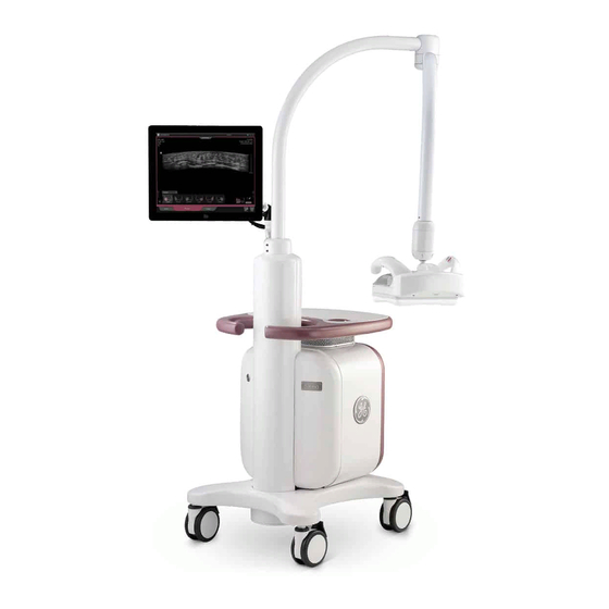
Figure 1-1. Invenia ABUS 2.0 The terms “scan station”, “product”, “device” or “instrument” may be used interchangeably throughout the manual to indicate the Invenia ABUS 2.0 product. ABUS=Automated Breast Ultrasound System Invenia ABUS 2.0 – System Setup and Basic Service Manual 4700-0043-00 Rev. 4... - Page 31 Locking Caster Wheels Signal flows from the transducer in the Scan Head (1), down the Weight Tower (4), through the Invenia ABUS 2.0 chassis (7), and finally to the Display (3). System configuration is stored on the itself. All necessary software is loaded from the hard drive upon powerup.
- Page 32 Figure 1-3. Minimum space around the exam bed. Maximum arm reach is 40 inches (1.02 m) ~0.76 m, or 30” clear space recommended ~0.61 m, or 24” clear space recommended Invenia ABUS 2.0 – System Setup and Basic Service Manual 4700-0043-00 Rev. 4...
-
Page 33: View-On Pacs
Instrument Overview View-on PACs After performing the exam on the Invenia ABUS 2.0, the exam can be transferred manually or automatically to a DICOM- compatible viewing station for review. After the review, the exam can be sent to a PACS for archiving, or to some other form of manual archive. -
Page 34: Important Conventions
Pictures, or icons, are used wherever they will reinforce the printed message. The icons, labels, and conventions used on the product and in the service information are described in this chapter. Invenia ABUS 2.0 – System Setup and Basic Service Manual 4700-0043-00 Rev. 4... - Page 35 Notes are used to provide important information about an item or a procedure. NOTE: Be sure to read the notes; the information contained in a note can often save you time or effort. Invenia ABUS 2.0 – System Setup and Basic Service Manual 4700-0043-00 Rev. 4...
-
Page 36: Standard Hazard Icons
Even if a symbol isn’t used in this manual, it may be included for your reference. Table 1-3: Standard hazard icons ELECTRICAL MECHANICAL HEAT PINCH MAGNET PACEMAKER 1-10 Invenia ABUS 2.0 – System Setup and Basic Service Manual 4700-0043-00 Rev. 4... -
Page 37: Standard Icons That Indicate That A Special Procedure Is To Be Used
Product icons Always refer to the product’s User Manual for a full list of labels used on the Invenia ABUS 2.0. Invenia ABUS 2.0 – System Setup and Basic Service Manual 1-11 4700-0043-00 Rev. 4... -
Page 38: Label Locations
It is important to refer to the current revision of the Invenia ABUS 2.0 Basic User Manual for a full list of product labels prior to servicing the system. The following figure shows the location of the GE Cares Label on the Invenia ABUS 2.0 monitor. 1-12 Invenia ABUS 2.0 –... -
Page 39: Safety Considerations
WALL OUTLET BEFORE YOU REMOVE ANY PARTS. BE CAUTIOUS WHENEVER POWER IS STILL ON AND COVERS ARE REMOVED. If the covers are removed from an operating Invenia ABUS 2.0, WARNING some metal surfaces may be warm enough to pose a potential heat hazard if touched, even while in shutdown mode. - Page 40 Because of the danger of introducing additional hazards, ONLY install GE approved parts. DO NOT perform any unauthorized modification of the equipment. Ensure that the Invenia ABUS 2.0 is turned off and unplugged WARNING Wait for at least 20 seconds for capacitors to discharge as there are no test points to verify isolation.
- Page 41 PPE should be used to reduce the risk of injury. Wear all PPE including gloves as indicated in the chemical WARNING MSDS. Invenia ABUS 2.0 – System Setup and Basic Service Manual 1-15 4700-0043-00 Rev. 4...
-
Page 42: Dangerous Procedure Warnings
ARE PRESENT IN THIS EQUIPMENT. USE EXTREME CAUTION WHEN HANDLING, TESTING AND ADJUSTING. Heat warning If the covers are removed from an operating Invenia ABUS 2.0, some metal surfaces may be warm enough to pose a potential heat hazard if touched, even while in shutdown mode. -
Page 43: Electrical Safety
Both the system power cable and the power connector must meet international electrical standards Electrical Warning DANGER Connecting an Invenia ABUS 2.0 to the wrong voltage level will most likely damage it. Transducer Follow these guidelines before connecting the transducer to the Invenia ABUS 2.0:... -
Page 44: Mechanical Safety
To avoid injury when you move the Touch Screen Display and the Display Arm, do not put your finger, hand, or object on the joint of the Display or the Display arm. 1-18 Invenia ABUS 2.0 – System Setup and Basic Service Manual 4700-0043-00 Rev. 4... - Page 45 Mechanical safety (continued) Personal Injury WARNING Invenia ABUS 2.0 weighs 100 kg (220 lb.) when ready for use. Care must be used when moving it or replacing its parts. Failure to follow the precautions listed below could result in personal injury, uncontrolled motion and costly damage.
- Page 46 Introduction Mechanical safety (continued) Equipment Damage CAUTION Before you move or transport the Invenia ABUS 2.0, make sure to lock the Touch Screen Display and Display Arm to prevent damage to the Invenia ABUS 2.0. Equipment Damage CAUTION Keep the heat venting holes on the Touch Screen Display unobstructed to avoid overheating of the Display.
- Page 47 Safety considerations Mechanical safety (continued) Equipment Damage CAUTION Do not transport Invenia ABUS 2.0 in a vehicle without locking the casters (wheels) and securing it as described in the User Manual. NOTE: Special care should be taken when transporting the Invenia ABUS 2.0 in a vehicle:...
-
Page 48: Electromagnetic Compatibility (Emc)
Proper installation following all comments noted in this service manual is required in order to achieve full EMC performance. 1-22 Invenia ABUS 2.0 – System Setup and Basic Service Manual 4700-0043-00 Rev. 4... -
Page 49: Electrostatic Discharge (Esd) Prevention
2.0 (near the power connector). Follow general guidelines for handling of electrostatic sensitive equipment. Risk of electrical shock, Invenia ABUS 2.0 must be turned off. WARNING Avoid all contact with electrical contacts, conductors and components. Always use non-conductive handles designed for the removal and replacement of ESD sensitive parts. -
Page 50: Customer Assistance
Refer to Figure 3-2 on page 3-35 to locate the System ID Serial Number on the Invenia ABUS 2.0. Specific label descriptions can be found in the user manuals. 1-24 Invenia ABUS 2.0 – System Setup and Basic Service Manual 4700-0043-00 Rev. 4... -
Page 51: Phone Numbers For Customer Assistance
Customer assistance Phone numbers for Customer Assistance Invenia ABUS 2.0 – System Setup and Basic Service Manual 1-25 4700-0043-00 Rev. 4... -
Page 52: System Manufacturer
Introduction System manufacturer Table 1-5: System manufacturer MANUFACTURER GE Medical Systems Ultrasound and Primary Care Diagnostics, LLC 9900 Innovation Drive Wauwatosa, WI 53226 1-26 Invenia ABUS 2.0 – System Setup and Basic Service Manual 4700-0043-00 Rev. 4... -
Page 53: Returning Parts
The USER/SERVICE staff should dispose of all the waste properly, per federal, state, and local waste disposal regulations. The Invenia ABUS 2.0 is not meant to be used for long-term storage of patient data or images. The user is responsible for the data on the system. - Page 54 1-28 Invenia ABUS 2.0 – System Setup and Basic Service Manual 4700-0043-00 Rev. 4...
- Page 55 Chapter 2 Site Preparations This chapter provides the information required to plan and prepare for the setup of an Invenia ABUS 2.0. Included are descriptions of the facility and electrical needs to be met by the purchaser of the Invenia ABUS 2.0.
-
Page 56: General Requirements
If the Invenia ABUS 2.0 is very cold or hot, do not turn on its CAUTION power until it has had a chance to acclimate to its operating environment. -
Page 57: Electrical Requirements
ABUS 2.0 without extension cords. Other outlets adequate for the external peripherals, medical and test equipment needed to support this Invenia ABUS 2.0 must also be present within 1 m (3.2 ft.) of the Invenia ABUS 2.0. Electrical installation must meet all current local, state, and national electrical codes. - Page 58 70% UT (30% dip in UT) for 25 cycles UT) for 25 cycles <5% UT (>95% dip in <5% UT (>95% dip in UT) for 5 s UT) for 5 s Invenia ABUS 2.0 – System Setup and Basic Service Manual 4700-0043-00 Rev. 4...
- Page 59 Interference (EMI) from radio frequencies, magnetic fields, and transients in the air or wiring. They also generate EMI. The Invenia ABUS 2.0 complies with limits as stated on the EMC label. However there is no guarantee that interference will not occur in a particular installation.
- Page 60 EMI prevention/abatement EMI RULE DETAILS Be aware of Radio • Keep the Invenia ABUS 2.0 at least 5 meters (15 feet) away from other EMI Frequency sources sources. • Special shielding may be required to eliminate interference problems caused by high frequency, high powered radio or video broadcast signals.
-
Page 61: Facility Needs
Potential sources of EMI (electromagnetic interference) should also be investigated before delivery. Dirt, static, and EMI can negatively impact Ultrasound system reliability. Invenia ABUS 2.0 – System Setup and Basic Service Manual 4700-0043-00 Rev. 4... -
Page 62: Time And Manpower Requirements
• Nearby waiting room, lavatory, and dressing room • Dual level lighting (bright and dim) • Storage area for Single Use Stabilization Membranes and Ultrasound Coupling Lotion Invenia ABUS 2.0 – System Setup and Basic Service Manual 4700-0043-00 Rev. 4... - Page 63 • Special shielding may be required if the console is to be operated in the vicinity of radio broadcast equipment. Invenia ABUS 2.0 – System Setup and Basic Service Manual 4700-0043-00 Rev. 4...
- Page 64 The Invenia ABUS 2.0 requires a dedicated power and ground for the proper operation of its Ultrasound equipment. A separate power outlet with a minimum 10 amp circuit breaker for 100-240 VAC.
- Page 65 • Maximum arm reach is 40” • ~0.76 m, or 30” clear side space recommended • ~0.61 m, or 24” clear front and back space recommended Invenia ABUS 2.0 – System Setup and Basic Service Manual 2-11 4700-0043-00 Rev. 4...
- Page 66 Site Preparations Room Layout (continued) Figure 2-2. Invenia ABUS 2.0 2-12 Invenia ABUS 2.0 – System Setup and Basic Service Manual 4700-0043-00 Rev. 4...
- Page 67 DICOM 3.0 Compliant • Worklist (DMWL) • Modality Performed Procedure Step (MPPS) • Store (SCU) • 10/100/1000 Base-T Ethernet • User-Replaceable Fan Filter • Remote Service Diagnostics Invenia ABUS 2.0 – System Setup and Basic Service Manual 2-13 4700-0043-00 Rev. 4...
- Page 68 Single-Use Stabilization Membrane • Single Volume Acquisition in less than 60 Seconds • Multi-Row LED Task Lighting • Removeable Scan Head Clear Cast Cover, for easier clean-up 2-14 Invenia ABUS 2.0 – System Setup and Basic Service Manual 4700-0043-00 Rev. 4...
- Page 69 Display: 17” High Resolution LCD Touch Screen • Cart: Mobile platform with 4-wheel steering and braking • Operating System: MS Windows 7 Embedded Standard, 64 bit Invenia ABUS 2.0 – System Setup and Basic Service Manual 2-15 4700-0043-00 Rev. 4...
-
Page 70: Networking Setup Requirements
With DICOM, images can be archived, stored, and retrieved faster, easier, and at a lower cost. 2-16 Invenia ABUS 2.0 – System Setup and Basic Service Manual 4700-0043-00 Rev. 4... -
Page 71: Dicom Setup Requirements
DICOM APPLICATION INFORMATION. A field for the make (manufacturer) and the revision of the device, is also included. This information may be useful for error solving. Invenia ABUS 2.0 – System Setup and Basic Service Manual 2-17 4700-0043-00 Rev. 4... -
Page 72: Environmental Dangers
AC outlets, or providing the device with extra protective earth, will be required in order to meet UL60601-1 and IEC60601-1 / IEC60601-1-1 standards for electrical leakage. 2-18 Invenia ABUS 2.0 – System Setup and Basic Service Manual 4700-0043-00 Rev. 4... -
Page 73: Patient Vicinity Ul60601-1 (Usa)
(examination table, dental chair, treatment booth, and the like) in its intended location, and extending vertically 2.29 m (7.5 ft.) above the floor. 1. Patient environment Invenia ABUS 2.0 – System Setup and Basic Service Manual 2-19 4700-0043-00 Rev. 4... - Page 74 Site Preparations 2-20 Invenia ABUS 2.0 – System Setup and Basic Service Manual 4700-0043-00 Rev. 4...
-
Page 75: Chapter 3 - System Setup
How to set up the system and how to check and test the unit, transducer, and external peripherals for electrical safety are also included in this procedure. Invenia ABUS 2.0 – System Setup and Basic Service Manual 4700-0043-00 Rev. 4... -
Page 76: Setup Time And Warnings
System performance and cooling require this. The system must be supplied by an adequately rated electrical CAUTION circuit. The capacity of the supply circuit must be as specified. Invenia ABUS 2.0 – System Setup and Basic Service Manual 4700-0043-00 Rev. 4... - Page 77 Operator Manual CAUTION The User Manual should be fully read and understood before operating the Invenia ABUS 2.0 and kept near the Ultrasound instrument for quick reference. Invenia ABUS 2.0 – System Setup and Basic Service Manual 4700-0043-00 Rev. 4...
-
Page 78: Receiving And Unpacking The Equipment
Remember to use relevant personal protecting equipment CAUTION (PPE) during packing and unpacking. Check with your local EHS representative. Work gloves are highly recommended to protect your hands while unpacking the crate. Invenia ABUS 2.0 – System Setup and Basic Service Manual 4700-0043-00 Rev. 4... -
Page 79: Receiving The Invenia Abus 2.0
• If YES; continue with the instructions in ‘Damage in transportation’ on page 3-6. • If NO; continue with the next step. Continue with the instructions in ‘Unpacking the Invenia ABUS 2.0’ on page 3-9. Invenia ABUS 2.0 – System Setup and Basic Service Manual... - Page 80 14 day period. Invenia ABUS 2.0 Transportation Box Label The Invenia ABUS 2.0 transportation crate label is located at the front of the transportation crate. Figure 3-1. Invenia ABUS 2.0 transportation box label Invenia ABUS 2.0 –...
- Page 81 Invenia ABUS 2.0 Transportation Box Label (continued) Table 3-2: Package Label Icons Label/Icon Purpose/Meaning Location Keep this way up. Package Fragile. Package Keep it away from rain. Package 2 levels at most. Package Invenia ABUS 2.0 – System Setup and Basic Service Manual 4700-0043-00 Rev. 4...
- Page 82 System Setup Table 3-2: Package Label Icons Label/Icon Purpose/Meaning Location Humidity Limitation Package Temperature Limitation Package Pressure Limitation Package Invenia ABUS 2.0 – System Setup and Basic Service Manual 4700-0043-00 Rev. 4...
-
Page 83: Unpacking The Invenia Abus 2.0
Instructions and pry bar are provided in the materials attached to the shipping crate. There are two sizes of Invenia ABUS 2.0 package, one is 1715x845x1650mm and the other is 1167x905x1807mm. Wear gloves to protect your hands from wood splinters or metal CAUTION edges. - Page 84 Table 3-3: Unpacking the Invenia ABUS 2.0 (for Size 1715x845x1650mm) Step Description Illustration Locate the pry tool taped to one of the sides of the crate. 3-10 Invenia ABUS 2.0 – System Setup and Basic Service Manual 4700-0043-00 Rev. 4...
- Page 85 NOTE: Ensure that the metal tabs are straightened until they are vertical, or the top will be difficult to remove. Invenia ABUS 2.0 – System Setup and Basic Service Manual 3-11 4700-0043-00 Rev. 4...
- Page 86 NOTE: Straighten the bottom tabs first, and then straighten the tabs on the side panels. Use caution when removing the crate side panels. 3-12 Invenia ABUS 2.0 – System Setup and Basic Service Manual 4700-0043-00 Rev. 4...
- Page 87 Receiving and Unpacking the Equipment Table 3-3: Unpacking the Invenia ABUS 2.0 (for Size 1715x845x1650mm) Step Description Illustration Use a pair of scissors to remove the clear plastic wrapping. Invenia ABUS 2.0 – System Setup and Basic Service Manual 3-13 4700-0043-00 Rev. 4...
- Page 88 System Setup Table 3-3: Unpacking the Invenia ABUS 2.0 (for Size 1715x845x1650mm) Step Description Illustration Remove the waterproof foil. 3-14 Invenia ABUS 2.0 – System Setup and Basic Service Manual 4700-0043-00 Rev. 4...
- Page 89 Receiving and Unpacking the Equipment Table 3-3: Unpacking the Invenia ABUS 2.0 (for Size 1715x845x1650mm) Step Description Illustration Remove the accessories box (membranes, lotion, network cable, power cord, etc..) Invenia ABUS 2.0 – System Setup and Basic Service Manual 3-15 4700-0043-00 Rev. 4...
- Page 90 Open ratchet until it is completely open and flat. c. Grab webbing from non-fixed side and pull to release webbing. 3-16 Invenia ABUS 2.0 – System Setup and Basic Service Manual 4700-0043-00 Rev. 4...
- Page 91 Receiving and Unpacking the Equipment Table 3-3: Unpacking the Invenia ABUS 2.0 (for Size 1715x845x1650mm) Step Description Illustration Remove the ramps from both sides of the Invenia ABUS 2.0. Invenia ABUS 2.0 – System Setup and Basic Service Manual 3-17 4700-0043-00 Rev. 4...
- Page 92 CAUTION: Ensure that the ramps are positioned with the white bounding boards outside of the black straps. These boards keep the wheels on the ramp. 3-18 Invenia ABUS 2.0 – System Setup and Basic Service Manual 4700-0043-00 Rev. 4...
- Page 93 Unpacking the Invenia ABUS 2.0 (for Size 1715x845x1650mm) Step Description Illustration Unlock the caster wheels, and then carefully move the Invenia ABUS 2.0 down the ramp. Invenia ABUS 2.0 – System Setup and Basic Service Manual 3-19 4700-0043-00 Rev. 4...
- Page 94 Description Illustration Remove the Scan Arm Assembly protective foam. Then, use a pair of scissors to cut the cable ties holding the protective Display Monitor foam. 3-20 Invenia ABUS 2.0 – System Setup and Basic Service Manual 4700-0043-00 Rev. 4...
- Page 95 Step Description Illustration Move up the Scan Arm Assembly then remove the Scan Arm Assembly and Display monitor protective foam. Remove the Tube Covers protective foam. Invenia ABUS 2.0 – System Setup and Basic Service Manual 3-21 4700-0043-00 Rev. 4...
- Page 96 Scan Head or other equipment. Remove all of the packaging and place the removed packaging back into the crate to store for possible future use. 3-22 Invenia ABUS 2.0 – System Setup and Basic Service Manual 4700-0043-00 Rev. 4...
- Page 97 Unpacking the Invenia ABUS 2.0 (for Size 1167x905x1807mm) Step Description Illustration Position the crate to allow room which have enough space to unload the Invenia ABUS 2.0. Invenia ABUS 2.0 – System Setup and Basic Service Manual 3-23 4700-0043-00 Rev. 4...
- Page 98 Table 3-4: Unpacking the Invenia ABUS 2.0 (for Size 1167x905x1807mm) Step Description Illustration Unlock 4pcs Butterfly Lock, open the package door and put it down carefully. 3-24 Invenia ABUS 2.0 – System Setup and Basic Service Manual 4700-0043-00 Rev. 4...
- Page 99 Open ratchet until it is completely open and flat. c. Grab webbing from non-fixed side and pull to release webbing. Invenia ABUS 2.0 – System Setup and Basic Service Manual 3-25 4700-0043-00 Rev. 4...
- Page 100 System Setup Table 3-4: Unpacking the Invenia ABUS 2.0 (for Size 1167x905x1807mm) Step Description Illustration Take out the accessory box. 3-26 Invenia ABUS 2.0 – System Setup and Basic Service Manual 4700-0043-00 Rev. 4...
- Page 101 Unpacking the Invenia ABUS 2.0 (for Size 1167x905x1807mm) Step Description Illustration Remove the baffle, then untie the nylon cable which tie to seal the high barrier PE bag. Invenia ABUS 2.0 – System Setup and Basic Service Manual 3-27 4700-0043-00 Rev. 4...
- Page 102 Unpacking the Invenia ABUS 2.0 (for Size 1167x905x1807mm) Step Description Illustration Unlock the caster wheels, and then carefully move the Invenia ABUS 2.0 down the ramp. 3-28 Invenia ABUS 2.0 – System Setup and Basic Service Manual 4700-0043-00 Rev. 4...
- Page 103 Receiving and Unpacking the Equipment Table 3-4: Unpacking the Invenia ABUS 2.0 (for Size 1167x905x1807mm) Step Description Illustration Use a pair of scissors to remove the clear plastic wrapping. Invenia ABUS 2.0 – System Setup and Basic Service Manual 3-29 4700-0043-00 Rev. 4...
- Page 104 Description Illustration Remove the Scan Arm Assembly protective foam. Then, use a pair of scissors to cut the cable ties holding the protective Display Monitor foam. 3-30 Invenia ABUS 2.0 – System Setup and Basic Service Manual 4700-0043-00 Rev. 4...
- Page 105 Step Description Illustration Move up the Scan Arm Assembly then remove the Scan Arm Assembly and Display monitor protective foam. Remove the Tube Covers protective foam. Invenia ABUS 2.0 – System Setup and Basic Service Manual 3-31 4700-0043-00 Rev. 4...
- Page 106 Scan Head or other equipment. Remove all of the packaging and place the removed packaging back into the crate to store for possible future use. 3-32 Invenia ABUS 2.0 – System Setup and Basic Service Manual 4700-0043-00 Rev. 4...
- Page 107 Lever locking (hinges) are made of zinc plated steel. • The inner reinforcements are made of Ethafoam (Polyethylene foam). • The plastic foil is made of LDPE (Low Density Polyethylene). Invenia ABUS 2.0 – System Setup and Basic Service Manual 3-33 4700-0043-00 Rev. 4...
-
Page 108: Preparing For Setup
EMI protection The Invenia ABUS 2.0 has been designed to minimize the effects of Electro-Magnetic Interference (EMI). Many of the covers, shields, and screws are provided primarily to protect the device from image artifacts caused by this interference. -
Page 109: Warning Label Locations
Preparing for Setup Warning Label Locations Figure 3-2. Rear Panel Label Location Invenia ABUS 2.0 – System Setup and Basic Service Manual 3-35 4700-0043-00 Rev. 4... - Page 110 8. Identification and Rating Plate–USA/Asia 120V 18. GE Cares console 9. CISPR Emissions Label Device and transducer IP Code GE Cares Label Placement Figure 3-3. GE Cares Label Location 3-36 Invenia ABUS 2.0 – System Setup and Basic Service Manual 4700-0043-00 Rev. 4...
- Page 111 IP Code Indicates the degree of protection Rating Plate • IPX0 provided by the enclosure per IEC60 • IPX1 529. Can be used in operating room environment. Invenia ABUS 2.0 – System Setup and Basic Service Manual 3-37 4700-0043-00 Rev. 4...
- Page 112 “Mains ON” indicates the power on Rear Panel position of the mains power breaker. Power Switch • Power Standby Switch CAUTION: This Power Switch DOES NOT ISOLATE Mains Supply. 3-38 Invenia ABUS 2.0 – System Setup and Basic Service Manual 4700-0043-00 Rev. 4...
- Page 113 General Electric. GE Cares label with System ID and Monitor service phone number. (rear panel) Invenia ABUS 2.0 – System Setup and Basic Service Manual 3-39 4700-0043-00 Rev. 4...
-
Page 114: Setup Warnings And Cautions
This defeats safety grounding. Do not wear the ESD wrist strap when you work on live circuits Electrical and more than 30 V peak is present. Hazard 3-40 Invenia ABUS 2.0 – System Setup and Basic Service Manual 4700-0043-00 Rev. 4... -
Page 115: Electrical Specifications
The User Manual(s) should be fully read and understood before operating the Invenia ABUS 2.0 and kept near the Ultrasound system for quick reference. Electrical specifications Connecting an Invenia ABUS 2.0 to the wrong voltage level will WARNING damage it. Verification of the system’s voltage setting Verify that the mains voltage specified for the Invenia ABUS 2.0... -
Page 116: Connections On The Rear Panel
GE. Connection from Invenia ABUS 2.0 to a DICOM destination on a network You will need one network cable to connect the Invenia ABUS 2.0 to a wall outlet on the hospital’s network. - Page 117 Location of the USB Flash Drive Ports You can install the USB Flash Drive in one of the following USB ports on the Invenia ABUS 2.0: two on the back panel of the Display, and one on the back panel of the chassis (lower left, next to the Ethernet port).
- Page 118 All unused ports will be locked down; no anti-virus software is required. Anti-virus software is not recommended to be placed on the Invenia ABUS 2.0. No alterations or modifications can be done via software on this medical device unless outlined and approved by the manufacturer.
-
Page 119: Switch On The Ac Power To Invenia Abus 2.0
Power button is located on the right front cover. 1. Switch ON the Power Mains Switch at the rear of the unit. 2. Press once on the On/Off button on the Invenia ABUS 2.0 to boot the unit. DO NOT unplug the power cord until after the complete WARNING shutdown procedure has been performed. -
Page 120: Setting Up The Invenia Abus 2.0
Windows desktop. This icon is available only with the Service login. • Configuration (gears): displays the configuration screens. • Exit: closes the application software. Figure 3-6. Service icons 3-46 Invenia ABUS 2.0 – System Setup and Basic Service Manual 4700-0043-00 Rev. 4... -
Page 121: Calibrating The Touch Screen Display
Figure 3-7. Calibrate Screen in System Configuration 3. Follow the onscreen instructions or tap the X in the upper right corner to close the configuration screen. Invenia ABUS 2.0 – System Setup and Basic Service Manual 3-47 4700-0043-00 Rev. 4... -
Page 122: Entering Institution Name
Figure 3-8. Institution Name in System Configuration 3. Follow the onscreen instructions or tap the X in the upper right corner to close the configuration screen. 3-48 Invenia ABUS 2.0 – System Setup and Basic Service Manual 4700-0043-00 Rev. 4... -
Page 123: Setting Up Time And Date Setting
2. Tap the Clock Setting button to open the Windows clock setting function. Figure 3-9. Clock setting in System Configuration Figure 3-10. Windows Date and Time Settings Invenia ABUS 2.0 – System Setup and Basic Service Manual 3-49 4700-0043-00 Rev. 4... - Page 124 Figure 3-11. Select time zone 5. Continue to the next configuration step or tap the X in the upper right corner to close the configuration screen. 3-50 Invenia ABUS 2.0 – System Setup and Basic Service Manual 4700-0043-00 Rev. 4...
-
Page 125: Setting Up The Windows Network
3. Double-click the “Local Area Connection” box. The Local Area Connection Status pop-up appears. Figure 3-13. Windows Connectivity Screen The Local Area Connection Status pop-up appears. Invenia ABUS 2.0 – System Setup and Basic Service Manual 3-51 4700-0043-00 Rev. 4... - Page 126 4. On the Local Area Connection Status pop-up, select “Properties” from the lower, left-hand corner of the pop-up. Figure 3-14. Local Area Connection Status Pop-Up The Local Area Network Properties pop-up appears. 3-52 Invenia ABUS 2.0 – System Setup and Basic Service Manual 4700-0043-00 Rev. 4...
- Page 127 “Internet Protocol Version 4 (TCP/IPv4)”. The Internet Protocol Version 4 (TCP/IPv4) Properties pop-up appears. Figure 3-15. Local Area Network Properties Pop-Up The Internet Protocol Version 4 (TCP/IPv4) Properties pop-up appears. Invenia ABUS 2.0 – System Setup and Basic Service Manual 3-53 4700-0043-00 Rev. 4...
- Page 128 Figure 3-16. Protocol Version 4 (TCP/IPv4) Properties Pop-Up 7. Type in the following information: • IP address (IPv4 address) • Subnet prefix length • Default gateway 3-54 Invenia ABUS 2.0 – System Setup and Basic Service Manual 4700-0043-00 Rev. 4...
-
Page 129: Setting Up Connectivity Between Invenia Abus 2.0 And Destinations
Setting up Connectivity between Invenia ABUS 2.0 and destinations 1. Refer to the Site Survey Planner for additional information. 2. Touch the Invenia ABUS 2.0 configuration icon, then the General tab. 3. Touch each Server button and enter the appropriate IP address and port numbers. -
Page 130: Customizing The Invenia Abus 2.0
• Storage • System • Service (only displays when Service logs in with the Service Login and Password) • Post-Processing • About Figure 3-17. General Menu 3-56 Invenia ABUS 2.0 – System Setup and Basic Service Manual 4700-0043-00 Rev. 4... -
Page 131: General Configuration
2. MPPS Server location 3. Destinations (single or multiple) 4. User Interface operating language 5. Manage System Storage. The Status gauge displays the Invenia ABUS 2.0 hard disk capacity (250GB) 6. Acoustic Power (%) 7. Scan depth (4.0cm is default) Figure 3-18. - Page 132 1. Manually record all the IP addresses and port information of the destinations you will be pushing files to. 2. Sign in with your service account on the Invenia ABUS 2.0. To add a destination a. Touch the Configuration button and on the General tab touch the destination button.
- Page 133 Touch the Return button to save the changes. NOTE: Export Images Settings: Unless customer is planning on reading the Invenia ABUS 2.0 images on PACS do not modify the default settings. To delete a destination a. Touch the Configuration button , and on the General tab touch the Destination button.
- Page 134 Any destination configured in the destination list can be selected prior to completing the exam information (manual or worklist). The drop down list is shown below. Figure 3-21. Selecting destination 3-60 Invenia ABUS 2.0 – System Setup and Basic Service Manual 4700-0043-00 Rev. 4...
- Page 135 Touch an exam that needs to be resent to a different destination. c. Touch the Resend button. d. Select the desired destination from the displayed list. Figure 3-22. Completed Exams Invenia ABUS 2.0 – System Setup and Basic Service Manual 3-61 4700-0043-00 Rev. 4...
- Page 136 NOTE: An account with a password set with any specific language characters may not be accessible if the language setting is changed on the system. 3-62 Invenia ABUS 2.0 – System Setup and Basic Service Manual 4700-0043-00 Rev. 4...
- Page 137 2. On the System tab, select the date and time display format from the dropdown lists of Date and Time, respectively. Figure 3-24. Date and Time Format Invenia ABUS 2.0 – System Setup and Basic Service Manual 3-63 4700-0043-00 Rev. 4...
-
Page 138: Scanning Protocols
Perform complete exam from only the patient’s left side (left side of the bed only) • Specify location of the transducer’s start position. Figure 3-25. Scanning Protocol Configuration Menu 3-64 Invenia ABUS 2.0 – System Setup and Basic Service Manual 4700-0043-00 Rev. 4... -
Page 139: Worklist Configuration (Continued)
Referring Physician • Accession Number • Study ID • Default Select Page (Worklist, Work Item Input) • Procedure DICOM Tag (Administrator) Figure 3-26. Worklist Configuration (User) Invenia ABUS 2.0 – System Setup and Basic Service Manual 3-65 4700-0043-00 Rev. 4... - Page 140 This facilitates better coordination of image storage servers by providing the server with a list of objects to send prior to or while actually sending such object. 3-66 Invenia ABUS 2.0 – System Setup and Basic Service Manual 4700-0043-00 Rev. 4...
-
Page 141: Storage Configuration
Storage Configuration The Storage Configuration menu allows you to configure how exam data is stored and deleted from the Invenia ABUS 2.0 hard drive. The Storage Forced Manual Cleanup lets you specify when the Invenia ABUS 2.0 will require exam data to be removed from the hard disk. -
Page 142: Service Configuration Menu
Description Delete or anonymize patient Clean System: Completely removes all patient data out of the image information data folder. Deletes any study on the Invenia ABUS 2.0. Keep 16-bit data ALWAYS set this to OFF. Export Anonymization On/Off -- When you export patient data to a USB drive, patient demographic information is removed. -
Page 143: About Page
The About Page shows the software version, lists 3rd Party Software used on the instrument. It also provides the online user manual through the Help “?” key. Figure 3-30. About Page Invenia ABUS 2.0 – System Setup and Basic Service Manual 3-69 4700-0043-00 Rev. 4... -
Page 144: Checking Connections Between The Invenia Abus 2.0 And Destinations
Figure 3-31. Network Indicator 2. Perform a scan on the Invenia ABUS 2.0. 3. At the Invenia ABUS 2.0, send a study from the software to the other destination: a. Turn on system power, log in as a typical user, and run through the functional checks found in Chapter 4. -
Page 145: Paperwork After Setup
During and after setup, the documentation (e.g. USB drives with documentation, User Manuals, Installation Manuals, etc.) for the Invenia ABUS 2.0 and the peripherals must be kept as part of the original Ultrasound system documentation. This ensures that all relevant safety and user information is available during the operation and service of the complete Ultrasound system. -
Page 146: Product Locator Installation Card
Product Locator card. From the factory, a sheet with five Product Locator cards for transportation and one for Installation are included. Figure 3-32. Product Locator Installation Card (Example) 3-72 Invenia ABUS 2.0 – System Setup and Basic Service Manual 4700-0043-00 Rev. 4... -
Page 147: Chapter 4 - Functional Checks
Invenia ABUS 2.0 functions. During new installations and Update Installations this chapter can be a great asset in determining if the Invenia ABUS 2.0 is working as it should. Invenia ABUS 2.0 – System Setup and Basic Service Manual... -
Page 148: General Procedures
Operate this Ultrasound system only when all board covers and frame panels are securely in place. The covers are required for safe operation, good Ultrasound system performance and cooling purposes. Invenia ABUS 2.0 – System Setup and Basic Service Manual 4700-0043-00 Rev. 4... -
Page 149: Overview
Checking the Software Version To check the version of software on the Invenia ABUS 2.0: 1. Log into the Invenia 2.0 2.0 software. 2. Click the configuration icon (lower, right corner of the Image tab) to open the System Configuration page. -
Page 150: Power On/Boot Up
HOSPITAL-GRADE TYPE (WHERE REQUIRED). Invenia ABUS 2.0 Scan Station requires all covers. CAUTION Operate this Invenia ABUS 2.0 Scan Station only when all board covers and frame panels are securely in place. The covers are required for safe operation, good Ultrasound system performance and cooling purposes. - Page 151 General procedures Connect AC (mains) Power to the Invenia ABUS 2.0 Connecting AC Power to the Invenia ABUS 2.0 ultrasound unit, involves preliminary checks of the power cord, voltage level and compliance with electrical safety requirements. 1. Ensure that the wall outlet is of appropriate type, and that the Power Mains Switch is turned off.
- Page 152 Functional Checks 2. Press once on the On/Off button on the Invenia ABUS 2.0 to boot the unit. Figure 4-3. On/Off Power shut down When you switch off the unit by pressing the Power button, the system performs an automatic shutdown sequence.
-
Page 153: Moving And Transporting The Invenia Abus 2.0
Disconnect the power cord prior to moving the system. Failure CAUTION to do so could cause you to run over the power cord or cause a tripping hazard. Invenia ABUS 2.0 – System Setup and Basic Service Manual 4700-0043-00 Rev. 4... - Page 154 DO NOT park or leave the system unattended on a slope. Even CAUTION if the rear brakes are locked, the system may slide down a ramp. Invenia ABUS 2.0 – System Setup and Basic Service Manual 4700-0043-00 Rev. 4...
- Page 155 7. Employ two to three persons to load and unload safely from a vehicle. Invenia ABUS 2.0 – System Setup and Basic Service Manual 4700-0043-00 Rev. 4...
- Page 156 2. Position the Articulating Display Arm, Scan Arm, and Scan Head Assembly away from a walking or work area. 3. Position the Scan Arm and Scan Head Assembly at the lowest position. 4-10 Invenia ABUS 2.0 – System Setup and Basic Service Manual 4700-0043-00 Rev. 4...
-
Page 157: Where Are The User Manuals And The Service Manual
Both the User Manuals and the Service Manual may be downloaded from the Common Documentation Library. You can download manuals from the Common Documentation Library (http:// www3.gehealthcare.com/en/Support/Support_Documentation_Library). Invenia ABUS 2.0 – System Setup and Basic Service Manual 4-11 4700-0043-00 Rev. 4... -
Page 158: Functional Checks
Functional Checks Functional checks Overview This section describes the functional checks used with the Invenia ABUS 2.0. Functional checks are used to verify that the product works as specified after performing maintenance procedures. Functional checks may also be used during troubleshooting. - Page 159 Access the Worklist and/or Enter Patient information manually. • Perform the exam. • Verify the exam. • Send the exam to the Workstation / PACS. • Perform Query/Retrieve process to PACS Invenia ABUS 2.0 – System Setup and Basic Service Manual 4-13 4700-0043-00 Rev. 4...
-
Page 160: Mechanical Functions Checks
• Doesn’t drop any pixels. Casters (Wheels) and Brakes Functional Checks Examine the wheels frequently for defects to avoid breaking or jamming and the brakes lock. 4-14 Invenia ABUS 2.0 – System Setup and Basic Service Manual 4700-0043-00 Rev. 4... -
Page 161: Connectivity Functional Checks
Exams transfer successfully • InSite is active • DICOM Worklist functions • DICOM MPPS functions For additional information see the Invenia ABUS 2.0 Basic User Manual (PN: 4700-0041-XX) Invenia ABUS 2.0 – System Setup and Basic Service Manual 4-15 4700-0043-00 Rev. 4... - Page 162 Functional Checks 4-16 Invenia ABUS 2.0 – System Setup and Basic Service Manual 4700-0043-00 Rev. 4...
- Page 163 Chapter 5 Components and Functions (Theory) This chapter examines the Invenia ABUS 2.0 architecture. It first identifies physical elements and then discusses the function of elements. Invenia ABUS 2.0 – System Setup and Basic Service Manual 4700-0043-00 Rev. 4...
-
Page 164: Introduction
The cart holds the Dual Box Chassis housing the two major electronics assemblies: the Ultrasound Box, and the PC Box. Figure 5-1. Invenia ABUS 2.0 Key to numbered items in Figure 5-1: Invenia ABUS 2.0 – System Setup and Basic Service Manual 4700-0043-00 Rev. 4... - Page 165 The cMST board handles the ultrasound analog signals, controls the relays in the MPSB Relay Board, and provides the control logic for the MFEPS power board. The cMST transfers Invenia ABUS 2.0 – System Setup and Basic Service Manual 4700-0043-00 Rev. 4...
- Page 166 This USB cable is routed to the Ultrasound Box where the USB signals are routed alongside other signal lines in a custom cable to the Weight Tower and Weight Controller board. Invenia ABUS 2.0 – System Setup and Basic Service Manual 4700-0043-00 Rev. 4...
-
Page 167: General Physical Design Of The Abus 2.0 System
PC Box (providing back end electronics)) • Service Table and covers • Weight Tower (providing sliding Scan Arm, adjustable compression pressure to Scan Head, support for operator Invenia ABUS 2.0 – System Setup and Basic Service Manual 4700-0043-00 Rev. 4... - Page 168 Scan Head. The board reports their state to the Motherboard via USB Power Check OK LED on top of PC Box Driven from ACDC box; lights when all outputs from ACDC box are operational Invenia ABUS 2.0 – System Setup and Basic Service Manual 4700-0043-00 Rev. 4...
-
Page 169: General Theory Of Operation
The following figure outlines general flow of data from Invenia ABUS 2.0 to external systems for image data handling. Invenia ABUS 2.0 – System Setup and Basic Service Manual 4700-0043-00 Rev. 4... -
Page 170: Image File Management
PC. They can be copied over Ethernet to a separate image viewing device (such as a GE Workstation) for image review and diagnosis, or to a USB drive, or to a PACS for storage. -
Page 171: System Elements And Their Operation
Motherboard and GPU, and the power supply and power supply PWAs. The chassis grillwork on the bottom has round holes permitting air intake from below, through the removable air filter. Invenia ABUS 2.0 – System Setup and Basic Service Manual 4700-0043-00 Rev. 4... - Page 172 I2C interface. The 12 VDC power for the fan board comes from the MFEPS board. Figure 5-5. Ultrasound Box fan tray 5-10 Invenia ABUS 2.0 – System Setup and Basic Service Manual 4700-0043-00 Rev. 4...
-
Page 173: Pc Box
Air is pulled up through the box by fans at the top. The box is removable as a single object; it is separate from the Ultrasound Box. Figure 5-6. CAD view of PC Box Invenia ABUS 2.0 – System Setup and Basic Service Manual 5-11 4700-0043-00 Rev. 4... - Page 174 Provide air flow from the PC Box to cool it Computing electronics in PC Box Motherboard and CPU Computing in the Invenia ABUS 2.0 is done in two places, the PC Box and the Ultrasound Box. PC Box computing is done by the Motherboard.
- Page 175 PCIe connector for cable to U/S Box cMST board The PC Box has an external-mounted PCIe connector, that provides signals to the PCIe cable between it and the U/S Box cMST board. Invenia ABUS 2.0 – System Setup and Basic Service Manual 5-13 4700-0043-00 Rev. 4...
-
Page 176: Weight Tower
2. Counterbalances the weight of the Scan Arm so it can be moved easily 3. Provides locking of Scan Head position 4. Provides adjustable compression pressure through an electromechanical system 5-14 Invenia ABUS 2.0 – System Setup and Basic Service Manual 4700-0043-00 Rev. 4... - Page 177 The following steps outline the sequence for scan setup and pressure control. Invenia ABUS 2.0 – System Setup and Basic Service Manual 5-15 4700-0043-00 Rev. 4...
- Page 178 Lower Weight by pressing the Abort Button (the red button located on the left-hand arm of the Scan Head Assembly). Then the Scan Arm is free to move. 5-16 Invenia ABUS 2.0 – System Setup and Basic Service Manual 4700-0043-00 Rev. 4...
-
Page 179: Scan Arm Assembly
The Ball Joint on the end of the Scan Arm enables the operator to swivel the Scan Head and at start of a scan, the joint is electronically commanded to lock position. Invenia ABUS 2.0 – System Setup and Basic Service Manual 5-17 4700-0043-00 Rev. 4... - Page 180 Scan Arm must be replaced as a unit. The Ball Joint can be disassembled but due to complexity is not field serviceable. Disassembly is not recommended. 5-18 Invenia ABUS 2.0 – System Setup and Basic Service Manual 4700-0043-00 Rev. 4...
-
Page 181: Scan Head
Box and from there, also by USB, to the PC Box. The Scan Head has two LED lighting strips illuminating the inside area around the Transducer. Invenia ABUS 2.0 – System Setup and Basic Service Manual 5-19 4700-0043-00 Rev. 4... - Page 182 1. Buttons: Begin/Stop Scan 2. Transducer 3. Buttons: Increase/Decrease compression 4. Single-Use Stabilizing Membrane 5. Scan Head Assembly Cover 6. LED Lights 7. Multi-Axis Ball Joint Lock 5-20 Invenia ABUS 2.0 – System Setup and Basic Service Manual 4700-0043-00 Rev. 4...
- Page 183 Transducer for different View Types (Lateral, Anterior/Posterior, and Medial). Arrows identify these position types 1. Anterior/Posterior 2. Lateral and Medial 3. Not Used Invenia ABUS 2.0 – System Setup and Basic Service Manual 5-21 4700-0043-00 Rev. 4...
- Page 184 Pressing a button once changes the weight by one step (about 7 pounds force). The touchscreen displays a picture identifying compression state. 5-22 Invenia ABUS 2.0 – System Setup and Basic Service Manual 4700-0043-00 Rev. 4...
-
Page 185: Display Arm Assembly With Touchscreen Monitor
Figure 5-10. Display Arm and Monitor The components of the arm are: 1.Shoulder joint 2.Extension arm 3.Elbow joint 4.Lift arm 5.Wrist joint 6.Display joint Invenia ABUS 2.0 – System Setup and Basic Service Manual 5-23 4700-0043-00 Rev. 4... -
Page 186: Controls, Displays, And Ports
Power Switch pushbutton on the side of the chassis. This is intended to be used for daily operations. The status of this pushbutton is sensed by the Motherboard. 5-24 Invenia ABUS 2.0 – System Setup and Basic Service Manual 4700-0043-00 Rev. 4... - Page 187 General theory of operation User displays and indicators Touchscreen monitor The Invenia ABUS 2.0 has a touchscreen display monitor that provides users with onscreen data entry, operating information and scan images. It has on-screen touch activated controls for system operation. The monitor shows error conditions and...
- Page 188 External access ports The base of the rear chassis cover has an externally-accessible Ethernet port and a USB port. Figure 5-11. Ethernet and USB service port 5-26 Invenia ABUS 2.0 – System Setup and Basic Service Manual 4700-0043-00 Rev. 4...
-
Page 189: Electrical / Electronic
Use of the Remote Diagnostics requires a User ID and an authorized password. For further information refer to Troubleshooting section of this document. Invenia ABUS 2.0 – System Setup and Basic Service Manual 5-27 4700-0043-00 Rev. 4... - Page 190 Programmable Gain Amplifier An amplifier whose gain can digitally controlled VCAT Voltage Controlled Attenuator A voltage divider whose ratio for dividing down the input can be set electronically 5-28 Invenia ABUS 2.0 – System Setup and Basic Service Manual 4700-0043-00 Rev. 4...
-
Page 191: Chapter 6 - Service Adjustments And Lubrication
Service Adjustments and lubrication This chapter describes how to test and make adjustments to the Invenia ABUS 2.0. You can use these to test the system for errors. Invenia ABUS 2.0 – System Setup and Basic Service Manual 4700-0043-00 Rev. 4... -
Page 192: Service Adjustments
This Chapter only covers the components or assemblies that require adjustments for the Invenia ABUS 2.0. System adjustments need to be performed by trained, qualified personnel. Contact GE for training. Invenia ABUS 2.0 – System Setup and Basic Service Manual 4700-0043-00 Rev. 4... -
Page 193: Scan Head Drive Screw Damper Adjustment
Damper then the Drive Screw when pushing. When Damper and Drive Screw are in the correct position, the Drive Screw will be centered in the Dampers. Invenia ABUS 2.0 – System Setup and Basic Service Manual 4700-0043-00 Rev. 4... -
Page 194: Ball Joint Lubrication
• Scan Head Cassette from the Scan Head • Clear Cast Cover 3. Rest the Scan Head Assembly on a flat, safe surface. The Scan Head Assembly must be supported for this procedure. Invenia ABUS 2.0 – System Setup and Basic Service Manual 4700-0043-00 Rev. 4... -
Page 195: Chapter 7 - Diagnostics/Troubleshooting
Very basic host, system and board level diagnostics are run whenever power is applied. Some Service Tools may be run at the application level. Invenia ABUS 2.0 – System Setup and Basic Service Manual 4700-0043-00 Rev. 4... -
Page 196: Service Safety Considerations
DANGER EQUIPMENT. USE EXTREME CAUTION WHEN HANDLING, TESTING, AND ADJUSTING. IF THE COVERS ARE REMOVED FROM AN OPERATING Invenia ABUS 2.0, SOME WARNING METAL SURFACES MAY BE WARM ENOUGH TO POSE A POTENTIAL HEAT HAZARD IF TOUCHED, EVEN WHILE IN SHUTDOWN MODE. -
Page 197: Gathering Troubleshooting Data
The error logs will be collected using Insite. • Error Logs • Crash Log (protected information) • Vital Product Data • DICOM Logs • Windows Event Logs • Diagnostic Logs • Service Logs Invenia ABUS 2.0 – System Setup and Basic Service Manual 4700-0043-00 Rev. 4... -
Page 198: Service Desktop
Basic Service access (Class A) – a user locally logged into the machine with Basic Service Access privilege. This level provides limited access to Service desktop widgets and utilities. Invenia ABUS 2.0 – System Setup and Basic Service Manual 4700-0043-00 Rev. 4... -
Page 199: Connecting To Service Desktop
Service Desktop Connecting to Service Desktop 1. Log into the Invenia ABUS 2.0. using your service ID and password. Figure 7-1. Login Screen 2. In the application software, locate and click the light colored GE icon in the Invenia ABUS 2.0 screen to open the Connectivity Menu. -
Page 200: Color Status
Item Icon Description InSite Indicators • White InSite connected to GE. User can send requests for service, but service is not connected. • White with blue radio waves. Service is connected and investigating the problem. • Red=Service desktop is active,... -
Page 201: Licenses
With Service Basic Access, these are the available options: (Class C) • HOME • Utilities • Delete Files • Gather Logs • Third Party Licenses • Agent Configuration Invenia ABUS 2.0 – System Setup and Basic Service Manual 4700-0043-00 Rev. 4... -
Page 202: Basic Class Access
Diagnostics/Troubleshooting Basic Class Access Basic configurations vary depending upon the purchased service level. Figure 7-3. Home with Class M Access Invenia ABUS 2.0 – System Setup and Basic Service Manual 4700-0043-00 Rev. 4... - Page 203 Service Desktop System Information System Information displays general information about the Invenia ABUS 2.0. When the Invenia ABUS 2.0 has been successfully configured with the back office, these elements will have the corresponding values: • Agent Registered will be Yes •...
- Page 204 No – The agent is not verified in the back office. Not Available – The agent is not running or has not been configured. Model Number GE part number for the Invenia ABUS 2.0. The same number as listed on the rating plate. Serial Number Serial number of the Invenia ABUS 2.0.
- Page 205 The information on Software Status is available to all service class licenses. To access Software Status, navigate to Utility > Service > Home. Figure 7-5. Software Status Invenia ABUS 2.0 – System Setup and Basic Service Manual 7-11 4700-0043-00 Rev. 4...
- Page 206 Version number of the base image software. Application Software Version Version number of the application software. Application Status Status of the application. Valid values are: Running Stopped 7-12 Invenia ABUS 2.0 – System Setup and Basic Service Manual 4700-0043-00 Rev. 4...
- Page 207 The information on System Status is available to Basic access licenses. To access System Status, navigate to Utility > Service > Home. Figure 7-6. System Status Invenia ABUS 2.0 – System Setup and Basic Service Manual 7-13 4700-0043-00 Rev. 4...
- Page 208 Voltage Displays the voltage monitoring of the Invenia ABUS 2.0 as normal, warning or error using the standard colors and icons. Includes voltage out-of-spec events including an overall count of the event warnings and errors for the last 30 days or last status checkpoint whichever is sooner.
- Page 209 This table shows all the elements available on Hardware Configuration with descriptions. Element DESCRIPTION Hardware component. Component Item Parameter with the vital product data (VPD). Value Actual value of the Item. Invenia ABUS 2.0 – System Setup and Basic Service Manual 7-15 4700-0043-00 Rev. 4...
- Page 210 To access this page, under System Status, select Temperature and then select Graphs. Figure 7-8. Graphs 7-16 Invenia ABUS 2.0 – System Setup and Basic Service Manual 4700-0043-00 Rev. 4...
- Page 211 Fan Status displays the details for each fan. The peak level of operation for the fans is 2500 RPM. To access this page, under System Status, select Temperature and then select Fan Status. Figure 7-9. Fan Status Invenia ABUS 2.0 – System Setup and Basic Service Manual 7-17 4700-0043-00 Rev. 4...
- Page 212 Upper Limit Warnings Number of high limit temperature warnings. Lower Limit Errors Number of low limit temperature errors. Number of high limit temperature errors. Upper Limit Errors 7-18 Invenia ABUS 2.0 – System Setup and Basic Service Manual 4700-0043-00 Rev. 4...
- Page 213 Service Desktop Voltage Use Voltage to troubleshoot problems with monitored FRUs and the AC voltage of the Invenia ABUS 2.0. Specifically, use these pages: • FRU Status • AC Voltage To access Voltage, navigate to Utility > Service > Home, and then under System Status, select Voltage.
- Page 214 FRU. To access this page, under System Status, select Voltage and then select FRU Status. Figure 7-10. FRU Status 7-20 Invenia ABUS 2.0 – System Setup and Basic Service Manual 4700-0043-00 Rev. 4...
- Page 215 Number of high limit voltage warnings. Upper Limit Warnings Number of low limit voltage errors. Lower Limit Errors Upper Limit Errors Number of high limit voltage errors. Invenia ABUS 2.0 – System Setup and Basic Service Manual 7-21 4700-0043-00 Rev. 4...
- Page 216 Last Alert Local Time Time the alert was last sent to the back office. Last Alert Sent Time Number of times that the alert has occurred. Count 7-22 Invenia ABUS 2.0 – System Setup and Basic Service Manual 4700-0043-00 Rev. 4...
- Page 217 This table shows all the elements available on Disk Drive Space with descriptions. Element DESCRIPTION C: Drive C: partition shows the graphical representation of the following: Used space in GB Available free space in GB Invenia ABUS 2.0 – System Setup and Basic Service Manual 7-23 4700-0043-00 Rev. 4...
- Page 218 The information on Network Configuration is available to Class M licenses. To access Network Configuration, navigate to Utility > Service > Home. Figure 7-13. Network Configuration 7-24 Invenia ABUS 2.0 – System Setup and Basic Service Manual 4700-0043-00 Rev. 4...
- Page 219 Service Desktop Figure 7-14. Network Configuration with More Details Invenia ABUS 2.0 – System Setup and Basic Service Manual 7-25 4700-0043-00 Rev. 4...
- Page 220 Default gateway for the wireless connection. MAC Address Address for the MAC for the wireless connection. Speed of the wireless connection. Speed (Mbps) Current status of the wireless connection. Status 7-26 Invenia ABUS 2.0 – System Setup and Basic Service Manual 4700-0043-00 Rev. 4...
-
Page 221: Utilities
OK. 4. When the gather log operation is complete, click the notification icon in the banner to view the location of the log files. Invenia ABUS 2.0 – System Setup and Basic Service Manual 7-27 4700-0043-00 Rev. 4... - Page 222 To access Third Party Software Licenses, select Utility (second page) > Service > Utilities > Third Party Software Licenses. Figure 7-16. Third Party Software Licenses 7-28 Invenia ABUS 2.0 – System Setup and Basic Service Manual 4700-0043-00 Rev. 4...
-
Page 223: Troubleshooting And System Messages
1 hour. Keep the system a distance of 18 inches Image Quality (~0.46 m) from curtains. CAUTION: DO NOT operate the system without a filter. Invenia ABUS 2.0 – System Setup and Basic Service Manual 7-29 4700-0043-00 Rev. 4... - Page 224 Image doesn’t transfer from the Invenia ABUS 2.0 Confirm that the Workstation Network Indicator light system is green. Shut down both the Invenia ABUS 2.0 and Workstation; then 1st reboot the Workstation, and 2nd reboot the Invenia ABUS 2.0. Lines in the Image Remove the transducer, then reverse it 180 degrees and plug it back in.
- Page 225 … at special times of the day (or night)? When? … at all locations in the hospital, or only in one room/area? … from time to time, no special pattern of time is observed? Invenia ABUS 2.0 – System Setup and Basic Service Manual 7-31 4700-0043-00 Rev. 4...
- Page 226 Interference (EMI) from radio frequencies, magnetic fields, and transients in the air or wiring. They also generate EMI. The Invenia ABUS 2.0 complies with limits as stated on the EMC label. However there is no guarantee that interference will not occur in a particular installation.
- Page 227 EMI prevention/abatement EMI RULE DETAILS Be aware of Radio • Keep the Invenia ABUS 2.0 at least 5 meters (15 feet) away from other EMI Frequency sources sources. • Special shielding may be required to eliminate interference problems caused by high frequency, high powered radio or video broadcast signals.
- Page 228 Ultrasound outlet. Different system Try another Invenia ABUS 2.0 at the same location and look for the same noise. If the noise is present on the new system too, the noise is most likely from an external source/equipment.
- Page 229 Verify if the noise change or disappear when the cables are removed. Often, this type of noise is due to grounding problems in the mains power system or that the Invenia ABUS 2.0 is sharing a power line with other equipment. Intermittent noise •...
- Page 230 Press Start on the Scan Head Assembly to begin the scan. Press Start button to start scan Press Start on the Scan Head Assembly to begin the scan. 7-36 Invenia ABUS 2.0 – System Setup and Basic Service Manual 4700-0043-00 Rev. 4...
- Page 231 A patient must be selected from the Worklist before scanning can begin. Please finish the current scan! The current scan is processing, the user must finish the current scan. Invenia ABUS 2.0 – System Setup and Basic Service Manual 7-37 4700-0043-00 Rev. 4...
-
Page 232: Invenia Abus 2.0 Messages
Local Port or AE Title. Only three lines of text are allowed for Institute Informational message. Please try the operation Address. again. 7-38 Invenia ABUS 2.0 – System Setup and Basic Service Manual 4700-0043-00 Rev. 4... - Page 233 The view type of the image stored in the Invenia Informational message. ABUS 2.0 Storage can’t be changed. Unauthorized to access the printer. Informational message. Invenia ABUS 2.0 – System Setup and Basic Service Manual 7-39 4700-0043-00 Rev. 4...
- Page 234 You have images pending int he DICOM queue. Informational message. You must restart Invenia ABUS 2.0 for the Please restart the application. configuration changes to take effect. 7-40 Invenia ABUS 2.0 – System Setup and Basic Service Manual 4700-0043-00 Rev. 4...
-
Page 235: Invenia Abus 2.0 Error Log
Invenia ABUS 2.0 creates three error logs per day: Daily error logs • ABUSApp_(serial number).(date).log.uct • ScannerApp_(serial number).(date).log.uct • ScannerAppMtCtrLib_(serial number).(date).log.uct Figure 7-17. ABUS daily error logs Invenia ABUS 2.0 – System Setup and Basic Service Manual 7-41 4700-0043-00 Rev. 4... - Page 236 Logs information from the Scan Head Assembly (Membrane, Buttons Pushed), Scan Arm (i.e. Ball Joint Lock) and Weight Controller (motor controller) For example: -ENTER MEMB_DETACHED by Event Membrane - attached 7-42 Invenia ABUS 2.0 – System Setup and Basic Service Manual 4700-0043-00 Rev. 4...
- Page 237 Logs information from the Scan Head Assembly (Membrane, Buttons Pushed), Scan Arm (i.e. Ball Joint Lock) and Weight Controller (motor controller) For example: -ENTER MEMB_DETACHED by Event Membrane - attached Invenia ABUS 2.0 – System Setup and Basic Service Manual 7-43 4700-0043-00 Rev. 4...
-
Page 238: Collecting Error Logs
Since there is not an ALT + D function, you might have to download the logs by selecting each individual file under the /Log folder: Figure 7-20. Downloading Log File Figure 7-21. Example of downloaded error logs 7-44 Invenia ABUS 2.0 – System Setup and Basic Service Manual 4700-0043-00 Rev. 4... -
Page 239: Common Error Codes For The Invenia Abus 2.0
Box) error codes does not overlap with old Verasonics (VDAS/ Acquisition) codes. Thus, the error codes related to GEUS and VDAS are unique to each system design. Invenia ABUS 2.0 – System Setup and Basic Service Manual 7-45 4700-0043-00 Rev. 4... -
Page 240: Error Code Identifications
Service Desktop to determine if the problem is caused by the Ultrasound Box fans or possible temperature reading errors on the cMST board sensors. 7-46 Invenia ABUS 2.0 – System Setup and Basic Service Manual 4700-0043-00 Rev. 4... - Page 241 Service Manual. However, some error codes/problems may still require the service team to collect and to analyze the system error logs. Invenia ABUS 2.0 – System Setup and Basic Service Manual 7-47 4700-0043-00 Rev. 4...
-
Page 242: Error Code List
GEUS fatal error DSP not detected requiring system restart 32001 GEUS Info GEUS information error 32002 GEUS Info GEUS information error requiring system restart 33001 GEUS Service GEUS service type error information category 7-48 Invenia ABUS 2.0 – System Setup and Basic Service Manual 4700-0043-00 Rev. 4... - Page 243 System will be shutdown! 35011 GEUS Failure ERR_BEP_011 - Bep Monitor abnormal,System will be shutdown! 35012 GEUS Failure ERR_APPLICATION_012 - Please reselect the application once again to continue. Invenia ABUS 2.0 – System Setup and Basic Service Manual 7-49 4700-0043-00 Rev. 4...
- Page 244 - Transducer scan head is disconnected 36013 GEUS Info INFO_TRANSDUCER_SCANHEAD_NOT_ACCEPT ED_013 - The transducer is not supported 36014 GEUS Info INFO_MPSB_BROKEN_014 - The MPSB is broken 7-50 Invenia ABUS 2.0 – System Setup and Basic Service Manual 4700-0043-00 Rev. 4...
-
Page 245: Chapter 8 - Replacement Procedures
Chapter 8 Replacement Procedures This chapter describes how to remove and replace the system’s filter and transducer. Invenia ABUS 2.0 – System Setup and Basic Service Manual 4700-0043-00 Rev. 4... -
Page 246: Warnings And Important Information
Warnings Energy Control and Power Lockout for Invenia ABUS 2.0. WARNING When servicing parts of the Invenia ABUS 2.0 where there is exposure to voltage greater than 30 volts: 1. Follow LOCKOUT/TAGOUT procedures. 2. Turn off the Power Mains Switch. -
Page 247: Manpower
Please contact the manufacturer or other authorized disposal company to decommission your equipment. Manpower Two people are required for: • Anything over 35 LBS (16 KG) Invenia ABUS 2.0 – System Setup and Basic Service Manual 4700-0043-00 Rev. 4... -
Page 248: Returning/Shipping Transducers And Repair Parts
Equipment being returned must be clean and free of blood and other infectious substances. GE policy states that body fluids must be properly removed from any part or equipment prior to shipment. GE employees, as well as customers, are responsible for ensuring that parts/equipment have been properly decontaminated prior to shipment. -
Page 249: Parts Disposal
Properly dispose of all old or used parts and media according to current policies and procedures. Never keep old software or leave old software at the customer site. Invenia ABUS 2.0 – System Setup and Basic Service Manual 4700-0043-00 Rev. 4... - Page 250 1. Power down the system. 2. Remove the filter which is located on the bottom of the Invenia ABUS 2.0. The filter is attached using Velcro. 3. Vacuum the filter. Invenia ABUS 2.0 – System Setup and Basic Service Manual 4700-0043-00 Rev. 4...
-
Page 251: Filter Replacement Functional Check
That the software runs through its initialization. • That each user type (User, Admin) can successfully login to the system. • And that the system images the patient successfully. Invenia ABUS 2.0 – System Setup and Basic Service Manual 4700-0043-00 Rev. 4... -
Page 252: Replacing The Transducer
Remove the four (4) screws securing the Transducer Cover assembly to the Transducer adapter mounting. NOTE: There are two (2) screws on either side of the Transducer Adapter Mounting. Invenia ABUS 2.0 – System Setup and Basic Service Manual 4700-0043-00 Rev. 4... - Page 253 Replacing the Transducer Hold the Transducer with one hand and the Transducer Cover assembly with the opposite hand. Gently pull the Transducer away from the Transducer Cover. Invenia ABUS 2.0 – System Setup and Basic Service Manual 4700-0043-00 Rev. 4...
-
Page 254: Replacing The Transducer (Continued)
10 in-lbs. (1.15 N-m) NOTE: There are two (2) screws on either side of the Transducer Adapter Mounting. Install the Scan Head assembly Clear Cast Cover. 8-10 Invenia ABUS 2.0 – System Setup and Basic Service Manual 4700-0043-00 Rev. 4... -
Page 255: Transducer Functional Check
Monitor. • Images evenly across the entire Touch Screen. 3D Volume Functional Checks Confirm that the 3D Volume: • Gets generated after each Scan View performed. Invenia ABUS 2.0 – System Setup and Basic Service Manual 8-11 4700-0043-00 Rev. 4... -
Page 256: Performing The Exam
Access the Worklist and/or Enter Patient information manually. • Perform the exam. • Verify the exam. • Send the exam to the Workstation / PACS. • Perform Query/Retrieve process to PACS 8-12 Invenia ABUS 2.0 – System Setup and Basic Service Manual 4700-0043-00 Rev. 4... -
Page 257: Replacing The Power Cord
2. Align the power cord prongs to match the receptacle, then securely push the cord straight back into the receptacle. 3. Pull the steel retaining clip down to retain the plug in the system. Invenia ABUS 2.0 – System Setup and Basic Service Manual 8-13 4700-0043-00 Rev. 4... -
Page 258: System Backup And Software Load
There are no user serviceable components inside the console. Refer all servicing to qualified service personnel only. Ensure that unauthorized personnel do not tamper with the unit. 8-14 Invenia ABUS 2.0 – System Setup and Basic Service Manual 4700-0043-00 Rev. 4... -
Page 259: Internal Component Replacement
There are no user serviceable components inside the console. Refer all servicing to qualified service personnel only. Ensure that unauthorized personnel do not tamper with the unit. Invenia ABUS 2.0 – System Setup and Basic Service Manual 8-15 4700-0043-00 Rev. 4... - Page 260 Replacement Procedures 8-16 Invenia ABUS 2.0 – System Setup and Basic Service Manual 4700-0043-00 Rev. 4...
-
Page 261: Chapter 9 - Renewal Parts
Chapter 9 Renewal Parts This chapter lists the renewal parts available for the Invenia ABUS 2.0. Invenia ABUS 2.0 – System Setup and Basic Service Manual 4700-0043-00 Rev. 4... -
Page 262: List Of Abbreviations
EXTERNAL INPUT/OUTPUT INTERNAL LIQUID CRYSTAL DISPLAY PCIe PCI EXPRESS POWER SUPPLY PRINTED CIRCUIT ASSEMBLY PRINTED WIRE ASSEMBLY POWER QUANTITY USED PER Invenia ABUS 2.0 SOLID STATE DRIVE Invenia ABUS 2.0 – System Setup and Basic Service Manual 4700-0043-00 Rev. 4... -
Page 263: Reordering Supplies
• ProteX Ultra Disinfectant Wipes - 60 ct Soft-pack w/ stay-put adhesive backing (not available in all markets) • ProteX Ultra Disinfectant Wipes -- 120 ct Canister pack (not available in all markets) Invenia ABUS 2.0 – System Setup and Basic Service Manual 4700-0043-00 Rev. 4... - Page 264 Invenia ABUS 2.0 Starter Kit:, contains: • Lotion, Ultrasound Coupling Pack, non-sterile (12 pack) • Invenia ABUS 2.0 Single Use Stabilization Membrane (50 pack) • Country-specific power cords (see below) Invenia ABUS 2.0 – System Setup and Basic Service Manual 4700-0043-00 Rev. 4...
-
Page 265: Chapter 10 - Care And Maintenance
Invenia ABUS 2.0 and peripherals. These procedures are intended to maintain the quality of the Ultrasound system’s performance. Read this chapter completely and familiarize yourself with the procedures before performing a task. Invenia ABUS 2.0 – System Setup and Basic Service Manual 10-1 4700-0043-00 Rev. 4... -
Page 266: Why Do Maintenance
Testing results, corrective action and the effects of corrective action must be documented and maintained on the site. As a GE service representative, you can help the customer with establishing, performing and maintaining records for a quality assurance program. - Page 267 NOTE: If preventative maintenance is performed, it should be done by a qualified ABUS-trained service person. Invenia ABUS 2.0 – System Setup and Basic Service Manual 10-3 4700-0043-00 Rev. 4...
- Page 268 ABUS 2.0 instrument and outlines items that may require special attention. As the GE Service Representative, you can emphasize that it is the customer’s responsibility to perform the tasks as indicated in the Care and Maintenance Schedule to ensure a high level of safety and performance of the Invenia ABUS 2.0 instrument.
- Page 269 3. Turn the Touch Screen back on and verify calibration is still accurate. Clean Filter(s) Clean the Invenia ABUS 2.0 air filter using the procedure on page 10-6. NOTE: The germicidal wipes listed below are approved for use with the Invenia ABUS 2.0.
- Page 270 Scan Head Assembly. Use disinfecting wipes to clean away residual lotion and other debris from the patient contact areas. See list of approved wipes on page 10-5. 10-6 Invenia ABUS 2.0 – System Setup and Basic Service Manual 4700-0043-00 Rev. 4...
- Page 271 See note on approved disinfectant wipes on page 10-5. Inspect transducer for wear. CAUTION: DO NOT use an alcohol-based solution to clean the transducer. Invenia ABUS 2.0 – System Setup and Basic Service Manual 10-7 4700-0043-00 Rev. 4...
- Page 272 2. Remove the air filter, which is located on the bottom of the Invenia ABUS 2.0. 3. Vacuum the air filter. 4. Replace the air filter, velcro side up. 10-8 Invenia ABUS 2.0 – System Setup and Basic Service Manual 4700-0043-00 Rev. 4...
- Page 273 2-2 recommendations, 7-32 copyrights, i-18 electrostatic discharge prevention, 1-23 covers and service table replacement, 8-15 customer assistance, 1-24 compliance, 1-22 phone numbers, 1-25 electromagnetic compatibility, 1-22 Invenia ABUS 2.0 – System Setup and Basic Service Manual Index-1 4700-0043-00 Rev. 4...
- Page 274 1-11 if the unit is very cold or hot, 2-2 important conventions, 1-8 important notices omission and errors, i-16 Index-2 Invenia ABUS 2.0 – System Setup and Basic Service Manual 4700-0043-00 Rev. 4...
- Page 275 3-33 renewal parts, 9-1 abbreviations, 9-2 replacement time and manpower requirements covers, 8-15 site preparations, 2-8 service table, 8-15 time format, 3-63 replacement procedures, 8-1 Invenia ABUS 2.0 – System Setup and Basic Service Manual Index-3 4700-0043-00 Rev. 4...
- Page 276 3-34 voltage settings, 3-41 warnings dangerous procedures, 1-16 power on/boot up, 4-4 receiving and unpacking, 3-4 replacement procedures, 8-2 what is EMC?, 1-22 Index-4 Invenia ABUS 2.0 – System Setup and Basic Service Manual 4700-0043-00 Rev. 4...
- Page 278 Invenia ABUS 2.0 – System Setup and Basic Service Manual 4700-0043-00 Rev. 4...