Siemens Simotics T-1FW6 Configuration Manual
Built-in torque motors external rotor
Hide thumbs
Also See for Simotics T-1FW6:
- Configuration manual (560 pages) ,
- Operating instructions manual (138 pages) ,
- Operating instructions manual (120 pages)
Table of Contents
Advertisement
Quick Links
Advertisement
Table of Contents

Related Manuals for Siemens Simotics T-1FW6


Summary of Contents for Siemens Simotics T-1FW6
- Page 3 Introduction Fundamental safety instructions Description of the motor SIMOTICS Mechanical properties Drive technology 1FW6 external rotor built-in Motor components and options torque motors Configuring Configuration Manual Technical data and characteristics Preparation for use Electrical connection Installation drawings/ dimension sheets Appendix 12/2020 A5E50516483B AA...
- Page 4 Note the following: WARNING Siemens products may only be used for the applications described in the catalog and in the relevant technical documentation. If products and components from other manufacturers are used, these must be recommended or approved by Siemens. Proper transport, storage, installation, assembly, commissioning, operation and maintenance are required to ensure that the products operate safely and without any problems.
-
Page 5: Introduction
Introduction Standard version This documentation only describes the functionality of the standard version. The machine OEM documents any extensions or changes to the motor made by it. For reasons of clarity, this documentation cannot contain all of the detailed information on all of the product types. - Page 6 Products (http://www.siemens.com/motioncontrol) My support Information on how to produce individual contents for your own machine documentation based on Siemens contents is available under the link: My support (https://support.industry.siemens.com/My/de/en/documentation) Note If you want to use this function, you must register once.
- Page 7 Introduction Training The following link provides information on SITRAIN - training from Siemens for products, systems and automation engineering solutions: SITRAIN (http://siemens.com/sitrain) Technical Support Country-specific telephone numbers for technical support are provided on the Internet under Contact: Technical Support (https://support.industry.siemens.com) If you need support with the topics "Application"...
- Page 8 Siemens does not control the information on these websites and is not responsible for the content and information provided there. The user bears the risk for their use.
- Page 9 This document contains recommendations relating to third-party products. Siemens accepts the fundamental suitability of these third-party products. You can use equivalent products from other manufacturers. Siemens does not accept any warranty for the properties of third-party products. 1FW6 external rotor built-in torque motors Configuration Manual, 12/2020, A5E50516483B AA...
- Page 10 Introduction 1FW6 external rotor built-in torque motors Configuration Manual, 12/2020, A5E50516483B AA...
-
Page 11: Table Of Contents
Table of contents Introduction ............................. 3 Fundamental safety instructions ......................13 General safety instructions ..................... 13 Equipment damage due to electric fields or electrostatic discharge ........19 Security information ........................ 20 Residual risks of power drive systems ..................21 Description of the motor ........................23 Highlights and benefits...................... - Page 12 Table of contents Maintenance and service intervals..................56 3.5.1 Safety instructions for maintenance ..................56 3.5.2 Maintenance work ........................62 3.5.3 Checking the insulation resistance ..................63 3.5.4 Inspection and change intervals for the coolant ..............64 Motor components and options ......................65 Motor components .........................
- Page 13 Table of contents Preparation for use ..........................133 Shipping and packaging ....................... 135 Transporting and storage ...................... 136 7.2.1 Packaging specifications for air transportation ..............137 7.2.2 Environmental conditions for long term storage and transport ..........138 7.2.3 Storage ..........................139 Electrical connection ...........................
- Page 14 Table of contents 1FW6 external rotor built-in torque motors Configuration Manual, 12/2020, A5E50516483B AA...
-
Page 15: Fundamental Safety Instructions
Fundamental safety instructions General safety instructions WARNING Electric shock and danger to life due to other energy sources Touching live components can result in death or severe injury. • Only work on electrical devices when you are qualified for this job. •... - Page 16 Fundamental safety instructions 1.1 General safety instructions WARNING Electric shock due to damaged motors or devices Improper handling of motors or devices can damage them. Hazardous voltages can be present at the enclosure or at exposed components on damaged motors or devices. •...
- Page 17 Therefore, if you move closer than 20 cm to the components, be sure to switch off radio devices or mobile telephones. • Use the "SIEMENS Industry Online Support app" only on equipment that has already been switched off. WARNING Unrecognized dangers due to missing or illegible warning labels Dangers might not be recognized if warning labels are missing or illegible.
- Page 18 Fundamental safety instructions 1.1 General safety instructions WARNING Unexpected movement of machines caused by inactive safety functions Inactive or non-adapted safety functions can trigger unexpected machine movements that may result in serious injury or death. • Observe the information in the appropriate product documentation before commissioning.
- Page 19 Fundamental safety instructions 1.1 General safety instructions WARNING Active implant malfunctions due to permanent-magnet fields Even when switched off, electric motors with permanent magnets represent a potential risk for persons with heart pacemakers or implants if they are close to converters/motors. •...
- Page 20 Fundamental safety instructions 1.1 General safety instructions CAUTION Burn injuries caused by hot surfaces In operation, the motor can reach high temperatures, which can cause burns if touched. • Mount the motor so that it is not accessible in operation. Measures when maintenance is required: •...
-
Page 21: Equipment Damage Due To Electric Fields Or Electrostatic Discharge
Fundamental safety instructions 1.2 Equipment damage due to electric fields or electrostatic discharge Equipment damage due to electric fields or electrostatic discharge Electrostatic sensitive devices (ESD) are individual components, integrated circuits, modules or devices that may be damaged by either electric fields or electrostatic discharge. NOTICE Equipment damage due to electric fields or electrostatic discharge Electric fields or electrostatic discharge can cause malfunctions through damaged... -
Page 22: Security Information
Siemens’ products and solutions undergo continuous development to make them more secure. Siemens strongly recommends that product updates are applied as soon as they are available and that the latest product versions are used. Use of product versions that are no longer supported, and failure to apply the latest updates may increase customer’s exposure... -
Page 23: Residual Risks Of Power Drive Systems
Fundamental safety instructions 1.4 Residual risks of power drive systems Residual risks of power drive systems When assessing the machine- or system-related risk in accordance with the respective local regulations (e.g., EC Machinery Directive), the machine manufacturer or system installer must take into account the following residual risks emanating from the control and drive components of a drive system: 1. - Page 24 Fundamental safety instructions 1.4 Residual risks of power drive systems For more information about the residual risks of the drive system components, see the relevant sections in the technical user documentation. 1FW6 external rotor built-in torque motors Configuration Manual, 12/2020, A5E50516483B AA...
-
Page 25: Description Of The Motor
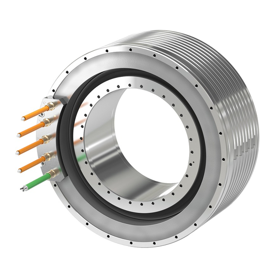
Description of the motor 1FW6 external rotor built-in torque motor Figure 2-1 1FW6 external rotor built-in torque motor with integrated cooling 1FW6 external rotor built-in torque motors Configuration Manual, 12/2020, A5E50516483B AA... -
Page 26: Highlights And Benefits
Highlights and benefits 2.1.1 Overview SIMOTICS T-1FW6 external rotor built-in torque motors are designed as built-in motors for use in low-speed direct drives with a high torque output. These built-in torque motors are liquid-cooled, permanent-magnet-excited, high-pole-number three-phase synchronous motors. The motors are delivered as components that are subsequently built-in. -
Page 27: Benefits
To ensure that the motor and the encoder are optimally integrated into the mechanical structure, Siemens offers its Application & Mechatronic Support Direct Motors service, see Catalog. For additional information, please contact your Siemens contact person, also refer to the Internet link in the Introduction under "Technical Support". -
Page 28: Intended Use
Where relevant, take into account deviations regarding approvals or country-specific regulations. • Contact your local Siemens office if you have any questions relating to correct use. • If you wish to use special versions and design versions whose technical details vary from the motors described in this document, then you must contact your local Siemens office. - Page 29 Description of the motor 2.2 Intended use WARNING Injury and material damage by not observing machinery directive 2006/42/EC There is a risk of death, serious injury and/or material damage if machinery directive 2006/42/EC is not carefully observed. • The products included in the scope of delivery are exclusively designed for installation in a machine.
-
Page 30: Technical Features And Environmental Conditions
Description of the motor 2.3 Technical features and environmental conditions Technical features and environmental conditions 2.3.1 Guidelines and standards Standards that are complied with The motors of the type series SIMOTICS S, SIMOTICS M, SIMOTICS L, SIMOTICS T, SIMOTICS A, called "SIMOTICS motor series" below, fulfill the requirements of the following directives and standards: •... - Page 31 UL or cUL mark on the rating plate! Quality systems Siemens AG employs a quality management system that meets the requirements of ISO 9001 and ISO 14001. Certificates for SIMOTICS motors can be downloaded from the Internet at the following link: Certificates for SIMOTICS motors (https://support.industry.siemens.com/cs/ww/de/ps/13347/cert)
-
Page 32: Danger From Strong Magnetic Fields
Description of the motor 2.3 Technical features and environmental conditions 2.3.2 Danger from strong magnetic fields Occurrence of magnetic fields Motor components with permanent magnets generate very strong magnetic fields. In the no- current condition, the magnetic field strength of the motors comes exclusively from the magnetic fields of components equipped with permanent magnets. - Page 33 Description of the motor 2.3 Technical features and environmental conditions For magnetic fields, you must carefully comply with the requirements laid down in the DGUV regulation 103-013 of the German Social Accident Insurance. CAUTION Safety distance to the rotor The rotor magnetic fields are permanent. If you come into direct bodily contact with the rotors, a static magnetic flux density of 2 T is not exceeded.
- Page 34 Description of the motor 2.3 Technical features and environmental conditions WARNING Risk of rotor permanent magnets causing crushing injuries The forces of attraction of magnetic rotors act on materials that can be magnetized. The forces of attraction increase significantly close to the rotor. The response threshold of 3 mT for risk of injury through attraction and causing a projectile effect is reached at a distance of 100 mm (Directive 2013/35/EU).
- Page 35 Description of the motor 2.3 Technical features and environmental conditions Note Installation device Because of the numerous installation situations and installation constraints, it is not possible to specify a general joining fixture. First aid in the case of accidents involving permanent magnets •...
-
Page 36: Technical Features
Description of the motor 2.3 Technical features and environmental conditions 2.3.3 Technical features Note The values specified in the following table only apply in conjunction with the system prerequisites described in the Chapter "System integration". Table 2- 1 Standard version of the 1FW67 built-in torque motor Technical feature Version Motor type... -
Page 37: Defining The Direction Of Rotation
Description of the motor 2.3 Technical features and environmental conditions 2.3.4 Defining the direction of rotation Direction of rotation If the built-in torque motor is connected with phase sequence U-V-W, and is fed from a three-phase system with a clockwise phase sequence, then the rotor will rotate counterclockwise. -
Page 38: Environmental Conditions For Stationary Use
Description of the motor 2.3 Technical features and environmental conditions 2.3.5 Environmental conditions for stationary use You can classify the ambient conditions for stationary use at weatherprotected locations according to the standard IEC 60721-3-3. The environmental effects and their limit values are defined in various classes in this standard. - Page 39 Description of the motor 2.3 Technical features and environmental conditions You can find additional data on the environmental conditions, such as ambient temperatures or conditions for transport and storage of the motors, in the relevant chapters of this documentation. 1FW6 external rotor built-in torque motors Configuration Manual, 12/2020, A5E50516483B AA...
-
Page 40: Scope Of Delivery
Description of the motor 2.3 Technical features and environmental conditions 2.3.6 Scope of delivery 2.3.6.1 1FW6 external rotor built-in torque motors • Rotor • Stator with ready-to-connect cooling system; one cable for the power connection and one cable for the signal connection with open core ends •... - Page 41 Description of the motor 2.3 Technical features and environmental conditions Any danger areas encountered during normal operation and when maintaining and servicing the motor must be identified using clearly visible warning and prohibit signs (pictograms) in the immediate vicinity of the danger (close to the motor). The associated texts must be available in the language of the country in which the product is used.
-
Page 42: Derating Factors
Description of the motor 2.4 Derating factors Derating factors For installation altitudes more than 2000 m above sea level, reduce the voltage stress of the motors according to the "Factors to reduce the maximum DC link voltage" table (reciprocal values from EN 60664-1 Table A. 2). Table 2- 5 Factors to reduce the maximum DC link voltage Installation altitude above sea level in m up to... -
Page 43: Selection And Ordering Data
Description of the motor 2.5 Selection and ordering data Selection and ordering data 2.5.1 Order designation The article number serves as order designation. The article number comprises a combination of digits and letters. When placing an order, it is sufficient just to specify the unique Article number. -
Page 44: 1Fw6 External Rotor Built-In Torque Motor
Description of the motor 2.5 Selection and ordering data 2.5.1.1 1FW6 external rotor built-in torque motor 1FW6 external rotor built-in torque motors Configuration Manual, 12/2020, A5E50516483B AA... -
Page 45: Rotor As Individual Component
Description of the motor 2.5 Selection and ordering data 2.5.1.2 Rotor as individual component 2.5.1.3 Ordering examples Example 1: Stator and rotor not joined, active part length 75 mm, for SINAMICS S120 drive system Motor Module with 30 A rated current/56 A maximum current Article number 1FW6720-2PB07-3AA3 Example 2: Stator and rotor not joined, active part length 75 mm, for SINAMICS S120 drive system... -
Page 46: Selection And Ordering Data For 1Fw67
Description of the motor 2.5 Selection and ordering data 2.5.2 Selection and ordering data for 1FW67 Table 2- 6 Overview Order designation Frame Rated torque Maximum Rated cur- Maximum Rated Max. speed size torque M rent current I speed at max. torque in Nm in Nm... -
Page 47: Rating Plate Data
Description of the motor 2.6 Rating plate data Rating plate data Technical data of the stator is provided on the rating plate (name plate). A second rating plate is provided loose for the stator. If, at a certain point in time, the stator and rotor are separated, then you must ensure that the stator and rotor can be assigned to one another at a later point in time. - Page 48 Description of the motor 2.6 Rating plate data 1FW6 external rotor built-in torque motors Configuration Manual, 12/2020, A5E50516483B AA...
-
Page 49: Mechanical Properties
Mechanical properties Cooling A water-cooling system dissipates the heat loss generated by the stator winding. • Connect the cooling ducts to the cooling circuit of a cooling device. You can find characteristic curves for the pressure drop of the coolant between the flow and return circuit of the coolers as a function of the volume flow rate in Chapter "Technical data and characteristics". -
Page 50: Cooling Circuit
Mechanical properties 3.1 Cooling Note No motor operation without liquid cooling • Ensure that the torque motor cooling system functions perfectly. • Only operate the motor in conjunction with liquid cooling. 3.1.1 Cooling circuit Cooling circuit requirements Avoid algae growth by using suitable chemical agents and opaque water hoses. We recommend that the cooling circuits be designed as closed systems. - Page 51 Mechanical properties 3.1 Cooling NOTICE Corrosion as a result of unsuitable materials used to connect the cooler Corrosion damage can occur if you use unsuitable materials to connect to the cooler. • We recommend that you use brass or stainless steel fittings when connecting the cooler.
- Page 52 Mechanical properties 3.1 Cooling Figure 3-1 Influence of the coolant inlet temperature Heat-exchanger unit Use a heat-exchanger unit to ensure an inlet temperature of 35 °C. More than one motor can be operated on a single heat-exchanger unit. The heat-exchanger units are not included in the scope of supply.
-
Page 53: Coolants
Power derating when using oil as coolant If you are using oil as coolant, then this can reduce the power loss dissipated by the cooler. Appropriately reduce the motor power. Please contact your local Siemens office if you have any questions. - Page 54 Mechanical properties 3.1 Cooling Requirements placed on the water Water which is used as basis for the coolant must comply as a minimum with the following requirements: • Chloride concentration: c < 100 mg/l • Sulfate concentration: c < 100 mg/l •...
-
Page 55: Degree Of Protection
Mechanical properties 3.2 Degree of protection Degree of protection NOTICE Damage to the motor caused by pollution If the area where the motor is installed is polluted and dirty, then the motor can malfunction and clog up. • Keep the area where the motor is installed free of all dirt and pollution. The machine construction surrounding the motor must fulfill degree of protection IP54 to EN 60529 as a minimum. -
Page 56: Vibration Behavior
Mechanical properties 3.3 Vibration behavior Vibration behavior The vibration response of build-in motors in operation essentially depends on the machine design and the application itself. As a result of an unfavorable machine design, configuration or system settings, resonance points can be excited, so that vibration severity level A according to EN 6003414 is not reached. -
Page 57: Noise Emission
Mechanical properties 3.4 Noise emission Noise emission WARNING Hearing damage Hearing damage may occur if the motor exceeds a sound pressure level of 70 dB (A) due to the type of mounting or pulse frequency. • Reduce the sound pressure level by implementing sound damping and/or soundproofing measures. -
Page 58: Maintenance And Service Intervals
Mechanical properties 3.5 Maintenance and service intervals Maintenance and service intervals 3.5.1 Safety instructions for maintenance WARNING Risk of injury as a result of undesirable rotary motion If, with the motor switched on, you work in the rotational range of the motor, and the motor undesirably rotates, this can result in death, injury and/or material damage. - Page 59 Mechanical properties 3.5 Maintenance and service intervals WARNING Risk of rotor permanent magnets causing crushing injuries The forces of attraction of magnetic rotors act on materials that can be magnetized. The forces of attraction increase significantly close to the rotor. The response threshold of 3 mT for risk of injury through attraction and causing a projectile effect is reached at a distance of 100 mm (Directive 2013/35/EU).
- Page 60 Mechanical properties 3.5 Maintenance and service intervals Note Installation device Because of the numerous installation situations and installation constraints, it is not possible to specify a general joining fixture. WARNING Risk of burning when touching hot surfaces There is a risk of burning when touching hot surfaces immediately after the motor has been operational.
- Page 61 Mechanical properties 3.5 Maintenance and service intervals WARNING Risk of electric shock due to incorrect connection There is a risk of electric shock if direct drives are incorrectly connected. This can result in death, serious injury, or material damage. • Motors must always be precisely connected up as described in these instructions.
- Page 62 • When performing disassembly work, observe the information in the Chapter "Decommissioning and disposal" of the operating instructions for "SIMOTICS T-1FW6 external rotor built-in motors". The motors have been designed for a long service life. Carefully ensure that maintenance work is correctly performed, e.g.
- Page 63 Siemens regarding personal injury or material damage. Siemens service centers are available to answer any questions you may have. Siemens Service Center addresses can be found at http://www.siemens.com/automation/service&support...
-
Page 64: Maintenance Work
Mechanical properties 3.5 Maintenance and service intervals 3.5.2 Maintenance work Performing maintenance work on the motor Note It is essential that you observe the safety information provided in this documentation. As a result of their inherent principle of operation, the motors are always wear-free. To ensure that the motor functions properly and remains free of wear, the following maintenance work needs to be carried out: •... -
Page 65: Checking The Insulation Resistance
Check the insulation resistance on the individual motors only according to the following procedure. • If a DC voltage > 1000 V or an AC voltage is necessary to test the machine/system, coordinate this test with your local Siemens office. • Carefully observe the operating instructions of the test device. Procedure 1. -
Page 66: Inspection And Change Intervals For The Coolant
Mechanical properties 3.5 Maintenance and service intervals 3.5.4 Inspection and change intervals for the coolant Test and replacement intervals of the cooling medium The test and replacement intervals for the cooling medium should be agreed with the manufacturers of the anti-corrosion agent and the cooling system. 1FW6 external rotor built-in torque motors Configuration Manual, 12/2020, A5E50516483B AA... -
Page 67: Motor Components And Options
Motor components and options Motor components 4.1.1 Overview of the motor design The built-in torque motor contains the following components: • Stator: comprises an iron core and a 3-phase winding. The winding is encapsulated to ensure that the heat loss can be dissipated more effectively. -
Page 68: Temperature Monitoring And Thermal Motor Protection
Motor components and options 4.1 Motor components 4.1.2 Temperature monitoring and thermal motor protection 4.1.2.1 Temperature monitoring circuits Temp-S and Temp-F The motors are equipped with the two temperature monitoring circuits – Temp-S and Temp-F – that are described below. •... - Page 69 Motor components and options 4.1 Motor components Every phase winding is monitored so that also uneven currents – and therefore the associated different thermal loads of the individual phase windings – are detected. For the following motion and/or operating states, the individual phase windings have different thermal loads, while the motor simultaneously outputs a torque: •...
- Page 70 Motor components and options 4.1 Motor components Temp-F The Temp-F temperature monitoring circuit comprises an individual temperature sensor. Contrary to Temp-S, this temperature sensor only monitors one phase winding. As a consequence, Temp-F is only used for monitoring the temperature and diagnosing the motor winding temperature.
-
Page 71: Technical Features Of The Temperature Sensors
Motor components and options 4.1 Motor components 4.1.2.2 Technical features of the temperature sensors Technical features of PTC temperature sensors Every PTC temperature has a "quasi-switching" characteristic. The resistance suddenly increases in the vicinity of the response threshold (nominal response temperature ϑ PTC temperature sensors have a low thermal capacity - and have good thermal contact with the motor winding. - Page 72 Motor components and options 4.1 Motor components Technical features of the Pt1000 temperature sensor The Pt1000 has a linear temperature resistance characteristic. In addition, the Pt1000 has a low thermal capacity and provides good thermal contact with the motor winding. Table 4- 2 Technical data of the Pt1000 PTC thermistor Name...
-
Page 73: Encoder
Siemens will support you with dimensioning, designing and optimizing your machine by means of measurement-based and computer-based analyses. You can obtain additional information from your Siemens contacts. You will find the Internet link on "Technical Support" in the "Introduction". Encoder system In the following text, encoder systems stand for angular measuring systems, rotary encoders, encoders etc. - Page 74 • Extremely stiff dynamic machine design to avoid the excitation of low-frequency mechanical oscillation Figure 4-3 Performance-resolution diagram Note Siemens does not accept any warranty for the properties/features of third-party products. 1FW6 external rotor built-in torque motors Configuration Manual, 12/2020, A5E50516483B AA...
- Page 75 As a consequence, a general recommendation for integrating the encoder cannot be given for all encoder types and axis concepts. To ensure that the encoder is optimally integrated into the mechanical structure, Siemens offers its Application & Mechatronic Support Direct Motors service, see Catalog. For additional information, contact your local Siemens office.
-
Page 76: Bearings
Motor components and options 4.1 Motor components 4.1.4 Bearings Selecting the bearing 1FW6 external rotor torque motors are built-in motors for directly driven rotary or swivel axes. To set up a complete drive unit, a bearing between the stator and rotor is required in addition to the phase-angle encoder system. -
Page 77: Brake Concepts
Motor components and options 4.1 Motor components 4.1.5 Brake concepts WARNING Uncontrolled coast down of the drive as a result of malfunctions Malfunctions on a rotating machine axes can lead to the drive coasting to a stop in an uncontrolled manner. •... - Page 78 Motor components and options 4.1 Motor components Braking and emergency stop concepts In the case of rotating axes that are restricted to a rotation angle of < 360°, damping and impact absorption elements at the limits of the rotation range offer reliable protection. To dissipate the kinetic energy of the rotating mass before it comes into contact with the damping elements, the following measures should be taken to support mechanical braking systems:...
- Page 79 Motor components and options 4.1 Motor components Deploying a holding brake Due to cogging torques, torque motors can be pulled into a preferable magnetic operating position if the motor is no longer supplied with power from the drive. If the drive is already at a standstill, this can cause unexpected movements in up to a half magnetic pole pitch in both directions.
-
Page 80: Options
Motor components and options 4.2 Options Options 4.2.1 Plug connector Connector type Connector size Article No. Power connection 6FX2003-0LA10 Power connection 6FX2003-0LA00 Signal connection 6FX2003-0SU07 4.2.2 Rotor flange variants The drilling pattern of the rotor is compatible with the commercially available, very rigid rotary table bearings. -
Page 81: Configuring
Siemens will support you with dimensioning, designing and optimizing your machine by means of measurement-based and computer-based analyses. You can obtain additional information from your Siemens contacts. You will find the Internet link on "Technical Support" in the "Introduction". 1FW6 external rotor built-in torque motors... -
Page 82: Configuring Software
Configuring 5.1 Configuring software Configuring software The STARTER commissioning tool offers • Commissioning • Optimization • Diagnostics Table 5- 1 Article number for STARTER Commissioning tool Article no. of the DVD STARTER 6SL3072-0AA00-0AG0 German, English, French, Italian, Spanish 1FW6 external rotor built-in torque motors Configuration Manual, 12/2020, A5E50516483B AA... -
Page 83: Configuring Workflow
Configuring 5.2 Configuring workflow Configuring workflow Requirements Your choice of torque motor depends on the following factors: • The peak and rms torque of the duty cycle required for the application • The required speed and angular acceleration • The installation space available •... - Page 84 Configuring 5.2 Configuring workflow Procedure Selecting the motors is generally an iterative process because – in particular with highly- dynamic direct drives – the moment of inertia of the motor type is a factor in determining the required torques. 1FW6 external rotor built-in torque motors Configuration Manual, 12/2020, A5E50516483B AA...
-
Page 85: General Mechanical Conditions
Configuring 5.2 Configuring workflow 5.2.1 General mechanical conditions Moment of inertia The kinetic energy generated by a rotating body is directly proportional to its moment of inertia J in kgm . The moment of inertia takes into account the rotating mass and its spatial distribution across the entire volume of the body with respect to the rotary axes. -
Page 86: Type Of Duty Cycle
Configuring 5.2 Configuring workflow 5.2.2 Type of duty cycle Uninterrupted duty S1 With uninterrupted duty S1, the motor runs permanently with a constant load. The load period is sufficient to achieve thermal equilibrium. The rated data is of relevance when dimensioning the motor for uninterrupted duty. NOTICE Motor overload An excessively high load can lead to shutdown, or if the temperature sensors are not... - Page 87 Configuring 5.2 Configuring workflow Example A motor should be operated with maximum current from the cold state. • I = 47 A, I = 26 A; this results in ν = 3.268 • t = 180 s The motor can be operated for a maximum of 66 s at maximum current. Intermittent duty S3 With intermittent duty S3, periods of load time Δt with constant current alternate with...
- Page 88 Configuring 5.2 Configuring workflow In this respect, the cycle duration should not exceed 10% of the thermal time constant t If a longer cycle duration is necessary, please contact your local Siemens office. Example When the thermal time constant t...
-
Page 89: Torque-Time Diagram
Configuring 5.2 Configuring workflow Example Figure 5-2 Example of a duty cycle with a speed-time diagram n(t), the resulting angular acceleration-time diagram α(t), and a machining torque-time diagram M 5.2.3 Torque-time diagram Required motor torque The required motor torque M is always the sum of the individual torques. - Page 90 Configuring 5.2 Configuring workflow Determining the required motor torque The frictional torque characteristic can be determined on the basis of the speed characteristic. The total formula can then be used to create the motor torque-time diagram (see diagram below) from which the required peak torque M can be read directly.
- Page 91 Configuring 5.2 Configuring workflow In addition to the peak torque M , the required rms torque M of the motor is also a mMAX decisive factor when dimensioning the motor. The rms torque M mainly responsible for the temperature rise in the motor can be derived from the motor torque-time diagram by means of quadratic averaging (root mean square) and must not exceed the rated torque M If the individual torques are stable in each section, the integral can be simplified to create a totals formula (see also the following diagram).
-
Page 92: Selecting Motors
70% of its rated torque, see also M * in Chapter "Technical data and characteristics". For exact configurations, contact your local Siemens office. Note Uneven current load Not all of the three phases are necessarily evenly loaded in all motor operating modes! Examples of uneven current load: •... -
Page 93: Motor Torque-Speed Diagram
Configuring 5.2 Configuring workflow 5.2.6 Motor torque-speed diagram Checking torques and speeds At high speeds, the maximum available motor torque is limited by the available DC link voltage. The speeds occurring in the motion sequence can exceed the maximum speed n MAX,MMAX specified for the motor type at the maximum torque M . - Page 94 Configuring 5.2 Configuring workflow Determining the motor torque-speed diagram If the motor torque-speed diagram is not available, then determine the motor torque-speed diagram from the following data taken from the "Motor torque speed diagram" figure. • Maximum torque M with the associated speed n MAX,MMAX •...
-
Page 95: Torque-Speed Requirements
Configuring 5.2 Configuring workflow 5.2.7 Torque-speed requirements Fulfilling the torque-speed requirements If the selected torque motor cannot fulfill the torque-speed requirements, the following options are available: • Larger motor If an operating point in the range A is required, a motor with a larger diameter and/or longer length is required (see motor 2 in the following diagram). -
Page 96: Checking The Moments Of Inertia
Configuring 5.2 Configuring workflow • Field weakening operation If an operating point in range C is required, then the motor must be operated in the field weakening range (see the following diagram). Advantage: Significantly higher speeds are possible. Disadvantage: The torques available are very low. A lower current is required, refer to the description for field weakening operation in Chapter "Technical data and characteristics"... -
Page 97: Selecting The Drive System Components For The Power Connection
To dampen the oscillations we recommend the use of the associated Active Interface Module or an HFD reactor with damping resistor. For specific details, refer to the documentation of the drive system being used or contact your local Siemens office. Note The corresponding Active Interface Module or the appropriate HFD line reactor must be used to operate the Active Line Module controlled infeed unit. -
Page 98: Calculation Of The Required Infeed
Configuring 5.2 Configuring workflow 5.2.10 Calculation of the required infeed Dimensioning the Active Infeed Use the drive's power balance to dimension the Active Infeed. The first important quantity to know is the mechanical power P to be produced on the mech motor shaft. -
Page 99: Mounting
Configuring 5.3 Mounting Mounting 5.3.1 Safety instructions for mounting WARNING Risk of death and crushing as a result of permanent magnet fields Severe injury and material damage can result if you do not take into consideration the safety instructions relating to permanent magnet fields. •... - Page 100 Configuring 5.3 Mounting WARNING Risk of rotor permanent magnets causing crushing injuries The forces of attraction of magnetic rotors act on materials that can be magnetized. The forces of attraction increase significantly close to the rotor. The response threshold of 3 mT for risk of injury through attraction and causing a projectile effect is reached at a distance of 100 mm (Directive 2013/35/EU).
- Page 101 Configuring 5.3 Mounting Note Installation device Because of the numerous installation situations and installation constraints, it is not possible to specify a general joining fixture. WARNING Electric shock caused by defective cables Defective connecting cables can cause an electric shock and/or material damage, e.g. by fire.
- Page 102 Configuring 5.3 Mounting WARNING Electrical shock hazard Every movement of the rotor compared with the stator and vice versa induces a voltage at the stator power connections. When the motor is switched on, the stator power connections are also at a specific voltage. If you use defective cable ports, you could suffer an electric shock.
-
Page 103: Forces That Occur Between The Stator And Rotor
Configuring 5.3 Mounting 5.3.2 Forces that occur between the stator and rotor Figure 5-10 Active forces when stators and rotors are joined ① Stator ② Rotor Axial force of attraction Radial attractive force Radial forces between the stator and rotor The following table shows the active radial forces in N per 0.1 mm centering error between the stator and rotor. -
Page 104: Specifications For Mounting The Torque Motor
Configuring 5.3 Mounting Example The eccentricity for a 1FW6720-2PB10-2Exx torque motor (active part length 100 mm) is, for example, 0.15 mm. The active radial force due to this centering error is therefore: 5.3.3 Specifications for mounting the torque motor Mounting system The following must be taken into account when the torque motor is mounted: •... - Page 105 Configuring 5.3 Mounting Screw material and tightening torques Screws of the following strength classes are required to fasten the motor to the machine construction. Table 5- 3 Required strength classes and tightening torques for the stator and rotor Screw Tightening torque (strength class) in Nm M8 (8.8)
-
Page 106: Procedure For Installing The Motor
Configuring 5.3 Mounting 5.3.4 Procedure for installing the motor Sequence for installing the motor WARNING Risk of injury and material damage Injury and/or destruction of motor components can occur if you do not observe the specified sequence when installing the motor. •... - Page 107 Configuring 5.3 Mounting Procedure 1. Prepare the mounting surfaces of the components to be installed and the machine as follows: – Deburr and round off any drill holes (e.g. cooling inlet/outlet drill holes) inside the machine housing. – Carefully remove machining debris, e.g. metal chips, dirt and foreign particles. 2.
-
Page 108: Cooler Connection
Configuring 5.3 Mounting 5.3.5 Cooler connection The connectors can generally be installed using standard tools. First determine the sum of the pressure losses of the individual cooling components and the associated piping. Compare the result with the cooling capacity of the cooling unit. You can connect the cooling system either by means of a connection integrated in the machine construction or via 1/4"... -
Page 109: Checking The Work Performed
Configuring 5.3 Mounting 5.3.6 Checking the work performed Checking the mounting work After installation has been completed, check that the rotor can freely rotate. Note that with short-circuited motor phases, the rotor is difficult to turn – even if no mechanical resistance is otherwise present. - Page 110 Configuring 5.3 Mounting 1FW6 external rotor built-in torque motors Configuration Manual, 12/2020, A5E50516483B AA...
-
Page 111: Technical Data And Characteristics
Technical data and characteristics The technical data and characteristics of 1FW6 external rotor built-in torque motors are specified in this chapter. This data collection provides the motor data required for configuration and contains a number of additional data for more detailed calculations for detailed analyses and problem analyses. -
Page 112: Explanations
Technical data and characteristics 6.1 Explanations Explanations 6.1.1 Explanations of the formula abbreviations Content of the data sheet The data specified on the data sheets is explained in the following section. It is categorized as follows: • Boundary conditions • Data at the rated operating point •... - Page 113 Technical data and characteristics 6.1 Explanations Note The sum of the mechanical power P output and power loss P yields the electric power mech drawn by the motor P Also refer to "Calculating the required infeed power." The rated electric power drawn by the motor at the rated operating point with M = M n = n can be calculated as follows: = 2π...
- Page 114 Technical data and characteristics 6.1 Explanations Physical constants Motor torque constants at a rotor temperature of 20 °C (refers to the lower linear T,20 range of the torque-current characteristic). Voltage constants for calculating the mutually induced line-to-line voltage. Motor constant for a winding temperature of T = 20 °C. M,20 The motor constant k (T) can be calculated for other temperatures:...
- Page 115 Technical data and characteristics 6.1 Explanations Phase resistance of the winding at a winding temperature of 20 °C. STR,20 The value of the phase resistance is required for calculating the power loss, among other things. R can be converted for other phase resistances as follows: (T) = R ∙...
- Page 116 Technical data and characteristics 6.1 Explanations Figure 6-3 Sample characteristic: "Pressure losses in the main cooler over volume flow rate" 1FW6 external rotor built-in torque motors Configuration Manual, 12/2020, A5E50516483B AA...
-
Page 117: Explanations Of The Characteristic Curves
Technical data and characteristics 6.1 Explanations 6.1.2 Explanations of the characteristic curves Torque-speed diagram with field weakening S1 duty S1 duty with field weakening S3 duty, cycle duration should not exceed 10% of the thermal time constant t S3 duty with field weakening, cycle duration should not exceed 10% of the thermal time constant t Voltage limit characteristic Limit characteristic for S1 duty Voltage limit characteristic with field weakening... - Page 118 Technical data and characteristics 6.1 Explanations that can be reached when motoring, are located to the left or below the "voltage limiting characteristic with field weakening" and to the right of the "voltage limiting characteristic". Note Above a certain speed, a Voltage Protection Module (VPM) is required; refer to the Chapter "AUTOHOTSPOT"...
-
Page 119: Data Sheets And Characteristics
Technical data and characteristics 6.2 Data sheets and characteristics Data sheets and characteristics Table 6- 1 Color coding of the M-n characteristics in the diagrams Color Resulting DC link voltage Converter output voltage Permissible line supply SINAMICS S120 (rms value) U voltage Line Module a max... -
Page 120: 1Fw6720-Xxb07-Xxxx
Technical data and characteristics 6.2 Data sheets and characteristics 6.2.1 1FW6720-xxB07-xxxx Data sheet 1FW6720-xxB07-3Axx Table 6- 2 1FW6720-xxB07-3Axx, 1FW6720-xxB07-3Axx-Z S80 Technical data Symbol Unit -xxB07-3Axx -xxB07-3Axx-Z S80 1FW6720 Boundary conditions DC link voltage Water cooling inlet temperature °C VORL Rated temperature of winding °C Data at the rated operating point Rated torque... - Page 121 Technical data and characteristics 6.2 Data sheets and characteristics Characteristics for 1FW6720-xxB07-3Axx Torque M versus speed n Torque M versus speed n 1FW6 external rotor built-in torque motors Configuration Manual, 12/2020, A5E50516483B AA...
- Page 122 Technical data and characteristics 6.2 Data sheets and characteristics Short-circuit braking torque M versus speed n Main cooler - pressure losses Δp over volume flow rate V ̇ 1FW6 external rotor built-in torque motors Configuration Manual, 12/2020, A5E50516483B AA...
-
Page 123: 1Fw6720-Xxb10-Xxxx
Technical data and characteristics 6.2 Data sheets and characteristics 6.2.2 1FW6720-xxB10-xxxx Data sheet 1FW6720-xxB10-2Exx Table 6- 3 1FW6720-xxB10-2Exx, 1FW6720-xxB10-2Exx-Z S80 Technical data Symbol Unit -xxB10-2Exx -xxB10-2Exx-Z S80 1FW6720 Boundary conditions DC link voltage Water cooling inlet temperature °C VORL Rated temperature of winding °C Data at the rated operating point Rated torque... - Page 124 Technical data and characteristics 6.2 Data sheets and characteristics Characteristics for 1FW6720-xxB10-2Exx Torque M versus speed n Torque M versus speed n 1FW6 external rotor built-in torque motors Configuration Manual, 12/2020, A5E50516483B AA...
- Page 125 Technical data and characteristics 6.2 Data sheets and characteristics Short-circuit braking torque M versus speed n Main cooler - pressure losses Δp over volume flow rate V ̇ 1FW6 external rotor built-in torque motors Configuration Manual, 12/2020, A5E50516483B AA...
- Page 126 Technical data and characteristics 6.2 Data sheets and characteristics Data sheet 1FW6720-xxB10-4Fxx Table 6- 4 1FW6720-xxB10-4Fxx, 1FW6720-xxB10-4Fxx-Z S80 Technical data Symbol Unit -xxB10-4Fxx -xxB10-4Fxx-Z S80 1FW6720 Boundary conditions DC link voltage Water cooling inlet temperature °C VORL Rated temperature of winding °C Data at the rated operating point Rated torque...
- Page 127 Technical data and characteristics 6.2 Data sheets and characteristics Characteristics for 1FW6720-xxB10-4Fxx Torque M versus speed n Torque M versus speed n 1FW6 external rotor built-in torque motors Configuration Manual, 12/2020, A5E50516483B AA...
- Page 128 Technical data and characteristics 6.2 Data sheets and characteristics Short-circuit braking torque M versus speed n Main cooler - pressure losses Δp over volume flow rate V ̇ 1FW6 external rotor built-in torque motors Configuration Manual, 12/2020, A5E50516483B AA...
-
Page 129: 1Fw6720-Xxb12-Xxxx
Technical data and characteristics 6.2 Data sheets and characteristics 6.2.3 1FW6720-xxB12-xxxx Data sheet 1FW6720-xxB12-4Fxx Table 6- 5 1FW6720-xxB12-4Fxx, 1FW6720-xxB12-4Fxx-Z S80 Technical data Symbol Unit -xxB12-4Fxx -xxB12-4Fxx-Z S80 1FW6720 Boundary conditions DC link voltage Water cooling inlet temperature °C VORL Rated temperature of winding °C Data at the rated operating point Rated torque... - Page 130 Technical data and characteristics 6.2 Data sheets and characteristics Characteristics for 1FW6720-xxB12-4Fxx Torque M versus speed n Torque M versus speed n 1FW6 external rotor built-in torque motors Configuration Manual, 12/2020, A5E50516483B AA...
- Page 131 Technical data and characteristics 6.2 Data sheets and characteristics Short-circuit braking torque M versus speed n Main cooler - pressure losses Δp over volume flow rate V ̇ 1FW6 external rotor built-in torque motors Configuration Manual, 12/2020, A5E50516483B AA...
-
Page 132: 1Fw6720-Xxb14-Xxxx
Technical data and characteristics 6.2 Data sheets and characteristics 6.2.4 1FW6720-xxB14-xxxx Data sheet 1FW6720-xxB14-4Fxx Table 6- 6 1FW6720-xxB14-4Fxx, 1FW6720-xxB14-4Fxx-Z S80 Technical data Symbol Unit -xxB14-4Fxx -xxB14-4Fxx-Z S80 1FW6720 Boundary conditions DC link voltage Water cooling inlet temperature °C VORL Rated temperature of winding °C Data at the rated operating point Rated torque... - Page 133 Technical data and characteristics 6.2 Data sheets and characteristics Characteristics for 1FW6720-xxB14-4Fxx Torque M versus speed n Torque M versus speed n 1FW6 external rotor built-in torque motors Configuration Manual, 12/2020, A5E50516483B AA...
- Page 134 Technical data and characteristics 6.2 Data sheets and characteristics Short-circuit braking torque M versus speed n Main cooler - pressure losses Δp over volume flow rate V ̇ 1FW6 external rotor built-in torque motors Configuration Manual, 12/2020, A5E50516483B AA...
-
Page 135: Preparation For Use
Preparation for use WARNING Risk of death and crushing as a result of permanent magnet fields Severe injury and material damage can result if you do not take into consideration the safety instructions relating to permanent magnet fields. • Refer to Chapter "Danger from strong magnetic fields (Page 30)". WARNING Incorrect packaging, storage and/or incorrect transport Risk of death, injury and/or material damage can occur if the devices are packed, stored, or... - Page 136 • Report any apparent defects / missing components to the appropriate Siemens office immediately. Siemens will not accept any claims relating to items missing from the delivery and which are submitted at a later date. 1FW6 external rotor built-in torque motors...
-
Page 137: Shipping And Packaging
Preparation for use 7.1 Shipping and packaging Shipping and packaging When shipping products that contain permanent magnets by sea or road, no additional packaging measures are required for protection against magnetic fields. Dangers are marked as follows on the original packaging of 1FW6 rotors: Table 7- 1 Warning signs according to BGV A8 and EN ISO 7010 and their significance Sign... -
Page 138: Transporting And Storage
Preparation for use 7.2 Transporting and storage Transporting and storage Note UN number for permanent magnets UN number 2807 is allocated to permit magnets as hazardous item. NOTICE Damage to the motor when incorrectly lifted Improper use of lifting devices can cause plastic deformation of the motor. •... -
Page 139: Packaging Specifications For Air Transportation
Preparation for use 7.2 Transporting and storage 7.2.1 Packaging specifications for air transportation When transporting products containing permanent magnets by air, the maximum permissible magnetic field strengths specified by the appropriate IATA Packing Instruction must not be exceeded. Special measures may be required so that these products can be shipped. Above a certain magnetic field strength, shipping requires that you notify the relevant authorities and appropriately label the products. -
Page 140: Environmental Conditions For Long Term Storage And Transport
Preparation for use 7.2 Transporting and storage 7.2.2 Environmental conditions for long term storage and transport Based on EN 60721-3-1 (for long-term storage) and EN 60721-3-2 (for transport) Table 7- 4 Climatic ambient conditions Lower air temperature limit: - 5 °C (deviates from 3K3) Upper air temperature limit: + 40 °C Lower relative humidity limit:... -
Page 141: Storage
Preparation for use 7.2 Transporting and storage 7.2.3 Storage The motors can be stored for up to two years under the following conditions: Storing indoors • Apply a preservation agent (e.g. Tectyl) to bare external components if this has not already been carried out in the factory. - Page 142 Preparation for use 7.2 Transporting and storage 1FW6 external rotor built-in torque motors Configuration Manual, 12/2020, A5E50516483B AA...
-
Page 143: Electrical Connection
Electrical connection NOTICE Destruction of the motor if it is directly connected to the three-phase line supply The motor will be destroyed if it is directly connected to the three-phase line supply. • Only operate the motors with the appropriately configured converters. WARNING Risk of electric shock If you connect the voltage to the stator as individual component, then there is a risk of... - Page 144 Electrical connection WARNING Electrical shock hazard Every movement of the rotor compared with the stator and vice versa induces a voltage at the stator power connections. When the motor is switched on, the stator power connections are also at a specific voltage. If you use defective cable ports, you could suffer an electric shock.
- Page 145 Electrical connection WARNING Electric shock caused by high leakage currents When touching conductive parts of the machine, high leakage currents can result in an electric shock. • For high leakage currents, observe the increased requirements placed on the protective conductor. The requirements are laid down in standards EN 61800-5-1 and EN 60204-1. •...
-
Page 146: Permissible Line System Types
Electrical connection 8.1 Permissible line system types Permissible line system types Permissible line system types and voltages The following table shows the permissible line voltages of TN line supply systems for the motors. Table 8- 1 Permissible line voltages of TN line supply systems, resulting DC link voltages and converter output voltages Permissible line Resulting DC link voltage U... -
Page 147: Circuit Diagram Of The Motor
Electrical connection 8.2 Circuit diagram of the motor Circuit diagram of the motor The circuit diagram of a stator looks like this: Figure 8-1 Circuit diagram of a stator Note Redundant temperature monitoring circuits Temp-S and Temp-F as reserve The motors are equipped with the following additional temperature monitoring circuits as reserve: •... -
Page 148: System Integration
Electrical connection 8.3 System integration System integration 8.3.1 Drive system Components The drive system that feeds a motor comprises an infeed module, a power module and a control module. For the SINAMICS S120 drive system, these modules are called "Line Modules", "Motor Modules"... - Page 149 Electrical connection 8.3 System integration The following diagram shows an example of a motor integrated into a system with the connection of Temp-S, Temp-F and an incremental encoder (sin/cos 1 V ) via SME120. Figure 8-3 System integration with SME120 (example) Note Connector sizes, see Chapter "Specifications for the signal cable on the stator (Page 152)".
- Page 150 Electrical connection 8.3 System integration Signal connection Only fully-threaded plug connectors can be used to connect signals. SPEED CONNECT connections are not compatible. Power connection Prefabricated cables with full thread plug connectors or SPEED-CONNECT plug connectors can be used as follows to connect the power: Table 8- 2 Compatibility Cable at the motor with...
-
Page 151: Sensor Module Sme12X
To dampen the oscillations we recommend the use of the associated Active Interface Module or an HFD reactor with damping resistor. For specific details, refer to the documentation of the drive system being used or contact your local Siemens office. Note The corresponding Active Interface Module or the appropriate HFD line reactor must be used to operate the Active Line Module controlled infeed unit. -
Page 152: Tm120 Terminal Module
Electrical connection 8.3 System integration 8.3.3 TM120 Terminal Module The TM120 Terminal Module is a module for evaluating temperature signals. The temperature sensors in the motor do not have safe electrical separation in order to achieve better thermal contact to the motor winding. Terminal Module TM120 evaluates the temperature sensors with safe electrical separation. -
Page 153: Electrical Connection Components
Electrical connection 8.3 System integration 8.3.5 Electrical connection components Location of the electrical connections The 1FW6 external rotor motors have an axial cable outlet for power and signals. ① Sensor cable ② Power cable (U, V, W, PE) Figure 8-5 Electrical connection, axial for 1FW6 external rotor 8.3.6 Data of the cable on the stator... -
Page 154: Specifications For The Signal Cable On The Stator
Electrical connection 8.3 System integration 8.3.7 Specifications for the signal cable on the stator Table 8- 4 Specifications for the signal cable on the stator Motor type Frame size Max. diameter No. of cores x Min. bending Max. height of Required con- in mm cross section... - Page 155 Electrical connection 8.3 System integration Table 8- 5 Pin assignment, Size 1.0 power connector Interface Figure 8-8 Pin configuration, M17 signal connector Table 8- 6 PIN assignment, M17 signal connector Interface sensor pair 1 Redundant interface sensor pair 2 -1R2: 1st Pt1000 -2R2: 2nd Pt1000 +1R1: 1st Pt1000 1TP1: 1st PTC 130 °C...
-
Page 156: Power Connection
Electrical connection 8.3 System integration 8.3.9 Power connection Connection assignment Table 8- 7 Power connection for torque motor Converter Torque motor/stator For information on connecting the power, also refer to the diagrams relating to "System integration". The rotor rotates counterclockwise if the torque motor is connected to phase sequence U, V, W. -
Page 157: Signal Connection
At the following link you can find information in the Internet on the topic of "Influence of high- frequency currents on thermal overload trips of circuit breakers (3RV, 3VU) and overload relays (3RU, 3UA)" and "Additional effects that can result in false trips". FAQ entry ID: 24153083 http://support.automation.siemens.com/WW/llisapi.dll?func=cslib.csinfo&objid=24153083&no deid0=20358027&caller=view&lang=de&extranet=standard&viewreg=WW&u=NDAwMDAxN wAA&siteID=cseus 8.3.10... - Page 158 Electrical connection 8.3 System integration Note Redundant temperature sensors Connect only one PTC thermistor triplet and one Pt1000. The redundant temperature sensors are reserve. Connect the open core ends of the redundant temperature sensors to grounded housing potential or insulate the open core ends. Connection assignment Table 8- 8 Core assignment for Temp-S and Temp-F temperature sensor cables...
- Page 159 Electrical connection 8.3 System integration Temperature sensor connection – standard Connect the signal cable as follows: • Using a plug connector at the SME12x (Sensor Module External) • With open cable ends at the TM120 The SME12x or the TM120 is connected to the converter via DRIVE-CLiQ. Refer to the diagrams for "System integration (Page 146)"...
-
Page 160: Shielding, Grounding, And Equipotential Bonding
Connect the power cable shield at the shield connection of the power module. Note Apply the EMC installation guideline of the converter manufacturer. For Siemens converters, this is available under document order No. 6FC5297-□AD30-0□P□. 1FW6 external rotor built-in torque motors... -
Page 161: Requirements For The Motor Feeder Cables
Electrical connection 8.3 System integration 8.3.12 Requirements for the motor feeder cables The selected cables must be able to withstand the mechanical forces caused by high accelerations and speeds. Further, the cables must be suitable for the bending stresses that occur. - Page 162 Electrical connection 8.3 System integration 1FW6 external rotor built-in torque motors Configuration Manual, 12/2020, A5E50516483B AA...
-
Page 163: Installation Drawings/Dimension Sheets
Installation drawings/dimension sheets Information on the installation drawings Fastening holes The schematic representation below shows the position tolerance for fastening holes according to EN ISO 1101:2008-08. The diameter "d" of the circular tolerance zone indicates the tolerance. Figure 9-1 Position tolerance for fastening holes The actual position of the hole's mid-point (actual dimension) must lie within the circular tolerance zone to enable the motor components to be attached without any problems. -
Page 164: Installation Drawing/Dimension Drawing For 1Fw6720-2Pbxx
Installation drawings/dimension sheets 9.2 Installation drawing/dimension drawing for 1FW6720-2PBxx Installation drawing/dimension drawing for 1FW6720-2PBxx 1FW6 external rotor built-in torque motors Configuration Manual, 12/2020, A5E50516483B AA... -
Page 165: Appendix
This document contains recommendations relating to third-party products. Siemens accepts the fundamental suitability of these third-party products. You can use equivalent products from other manufacturers. Siemens does not accept any warranty for the properties of third-party products. A.1.1 Supply sources for connection components and accessories for heat-exchanger... -
Page 166: Supply Sources For Anti-Corrosion Agents
Appendix A.1 Manufacturer recommendations Helmut Schimpke Industriekühlanlagen GmbH + Co. KG www.schimpke.de Hydac International GmbH www.hydac.com Rittal GmbH & Co. KG www.rittal.de A.1.3 Supply sources for anti-corrosion agents TYFOROP CHEMIE GmbH Anti-corrosion protection: www.tyfo.de Tyfocor Clariant Produkte (Deutschland) GmbH Anti-corrosion protection: www.clariant.de Antifrogen N A.1.4... -
Page 167: List Of Abbreviations
Appendix A.2 List of abbreviations List of abbreviations Binding national health and safety at work regulations in Germany, accident prevention regulations Conformité Européenne (European Conformity) Deutsches Institut für Normung (German standards organization) DRIVE-CLiQ European Union Electromotive force Electromagnetic compatibility Europäische Norm (European standard) High-frequency damping Hardware IATA... -
Page 168: Environmental Compatibility
Appendix A.3 Environmental compatibility Environmental compatibility A.3.1 Environmental compatibility during production • The packaging material is made primarily from cardboard. • Energy consumption during production was optimized. • Production has low emission levels. A.3.2 Disposal Recycling and disposal For environmentally-friendly recycling and disposal of your old device, please contact a company certified for the disposal of waste electrical and electronic equipment, and dispose of the old device as prescribed in the respective country of use. -
Page 169: Disposal Of 1Fw6 Rotors
Appendix A.3 Environmental compatibility Main constituents of a proper disposal procedure • Complete demagnetization of the components that contain permanent magnets • Components that are to be recycled should be separated into: – Electronics scrap (e.g. encoder electronics, Sensor Modules) –... -
Page 170: Disposal Of Packaging
Appendix A.3 Environmental compatibility A.3.2.3 Disposal of packaging Packaging materials and disposal The packaging and packing aids we use contain no problematic materials. With the exception of wooden materials, they can all be recycled and should always be disposed of for reuse. -
Page 171: Index
Index Accidents Degree of protection, 34, 53 First aid, 33 Derating factors, 40 Accuracy, 24 Design, 34 Ambient conditions, 36 Direction of rotation, 35 Anti-corrosion protection, 52 Disposal, 166 Area of application, 26 Encoder system, 71 Bearings, 74 Environmental compatibility, 166 Braking, 75, 75 Evaluation Braking and emergency stop concepts, 76... - Page 172 Malfunctions Sensor Module External SME12x, 149 Braking, 75 Shielding, 158 Motor Short-time duty, 84 Circuit diagram, 145 Siemens Service Center, 5 Components, 65 SMC20 Sensor Module Cabinet-Mounted, 150 Disposal, 167 STARTER, 80 Motor installation, 97 Storage, 133 Mounting system, 102...