Table of Contents
Advertisement
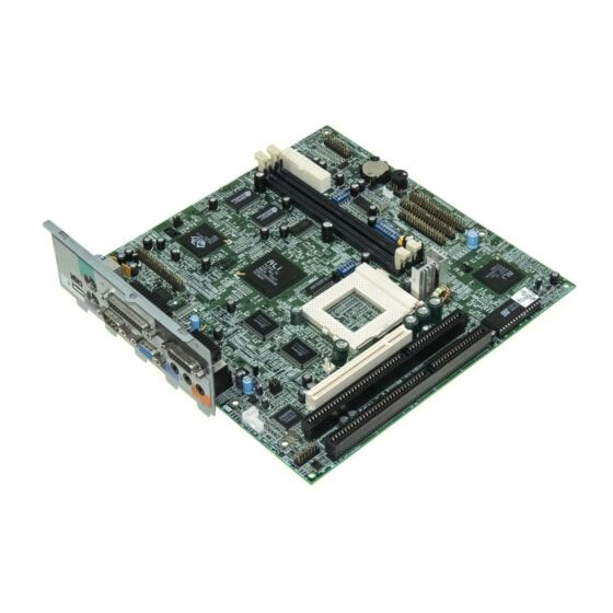
V70MA System Board
The V70MA is an all-in-one, high-performance system board that
supports the Intel Pentium processor with MMX (MultiMedia
eXtensions) technology.
The MMX feature enables the system to
handle multimedia functions and enhance the performance of 32-bit
applications.
The system memory is upgradable to 256 MB via the onboard two
168-pin DIMM (Double In-line Memory Module) sockets.
These
sockets accommodate 8-, 16-, 32-, 64- and 128-MB DIMMs. The
system board also comes with 512-KB second-level cache already
integrated in the CPU.
To fully support multimedia functions, the board incorporates a high-
performance 3-D video controller with AGP (Accelerated Graphics
Port) feature, 2- or 4-MB SGRAM (Synchronous Graphics Random
Access Memory), and a 3-D audio controller.
Onboard I/O (input/output) interfaces are comprised of two UART
(Universal
Asynchronous
Receiver-Transmitter)
16C550
serial
interfaces (one port and one connector), a parallel port with SPP
(Standard Parallel Port)/ECP (Extended Capabilities Port)/EPP
(Enhanced Parallel Port) support, and PS/2 keyboard and mouse
ports.
Two USB (Universal Serial Bus) ports, one VGA (Video
Graphics Accelerator) port, one Feature connector, one Microphone-in
port, one Line-in port, one Line-out port, and one Game/MIDI (Musical
Instrument Digital Interface) port are also added to the board design to
enable the system to support additional peripherals.
For expansion, the board comes with two ISA (Industry Standard
Architecture) slots and one PCI (Peripheral Component Interface) slot.
Special features such as PnP (Plug-and-Play) support, Power
Management, Wireless Communication, Hardware Monitoring, Wake-
on Ring, and Wake-on LAN (Local Area Network) functions are also
supported. These functions are individually discussed in this chapter.
V70MA System Board
1
Advertisement
Table of Contents

Related Manuals for Acer V70MA


Summary of Contents for Acer V70MA
- Page 1 V70MA System Board The V70MA is an all-in-one, high-performance system board that supports the Intel Pentium processor with MMX (MultiMedia eXtensions) technology. The MMX feature enables the system to handle multimedia functions and enhance the performance of 32-bit applications. The system memory is upgradable to 256 MB via the onboard two 168-pin DIMM (Double In-line Memory Module) sockets.
-
Page 2: Major Components
The system is fully compatible with MS-DOS V6.X, OS/2, SCO UNIX, Windows NT, and Windows 95/98 operating systems. Major Components The system board has the following major components: • A Zero Insertion Force (ZIF) CPU socket that accommodates Intel, AMD, or Cyrix/IBM Pentium CPU with MMX technology, running at 233, 250, 266, 300, 333, or 350 MHz •... - Page 3 One SPP/ECP/EPP high-speed parallel port • Two USB ports • One standard VGA port • One Microphone-in port • One Line-in port • One Line-out port • One Game/MIDI port • Two ISA slots and one PCI slot (one PCI-/ISA-shared) V70MA System Board...
-
Page 4: System Board Layout
System Board Layout Figure 1 shows the locations of the major components on the system board. 25 24 33 32 23 22 7 8 9 10 11 12 13 USB ports CPU socket PS/2 mouse/keyboard port Voltage controller with heatsink Parallel port IDE 1 connector VGA port... -
Page 5: Jumper And Connector Locations
Jumpers and Connectors Jumper and Connector Locations Figure 2 shows the jumper and connector locations on the system board. Figure 2 System Board Jumper and Connector Locations The blackened pin of a jumper or a connector represents pin 1. V70MA System Board... -
Page 6: Jumper Settings
Jumper Settings The following table lists the possible jumper settings: Table 1 Jumper Settings Jumper Setting Function VGA Interrupt Disabled Enabled Wake-on LAN Active low Active high Audio Line-in Source AMC connector 1-2, 4-5 Line-in connector 2-3, 5-6 CPU Type AMD K6S-300 JPX1 Other CPUs... - Page 7 Jumper Settings (continued) SW2 Settings CPU Core Clock Multiplier CPU Type P55C CPU Core Voltage Voltage SW3 Settings AMD K6S-300 Voltage Select Voltage 3.45V 3.6V Password Checking Function Check password Bypass password M1542 Bus Frequency Frequency * Default setting V70MA System Board...
-
Page 8: System Board Connectors
Onboard Connector Functions Table 2 lists the onboard connectors and their respective functions. Table 2 System Board Connectors Connector Function USB port Power LED (pins 1-3) HDD LED (pins 4-7) Reset button (pins 8-9) Power button (pins 10, 20) IrDA connector (pins 14-19) Turbo LED (pins 11-13) Upper: PS/2 mouse port Lower: PS/2 keyboard port... -
Page 9: Installation Precautions
Follow the ESD precautions in section 4.1 before handling a system component. Remove any expansion boards or peripherals that block access to the DIMM sockets or CPU connector. See the following sections for specific instructions on the component you wish to install. V70MA System Board... -
Page 10: Post-Installation Instructions
Do not attempt the procedures described in the following sections unless you are a qualified service technician. Post-installation Instructions Observe the following after installing a system component: See to it that the components are installed according to the step- by-step instructions in their respective sections. Make sure you have set all the required jumpers. -
Page 11: Memory Configurations
8 MB 16 MB 16 MB 16 MB 32 MB 32 MB 32 MB 64 MB 64 MB 64 MB 128 MB 128 MB 128 MB 256 MB Installing a DIMM Follow these steps to install a DIMM: V70MA System Board... -
Page 12: Removing A Dimm
Open the clips on the socket. Align the DIMM with the socket. Press the DIMM into the socket until the clips lock into the DIMM. Figure 3 Installing a DIMM The DIMM socket is slotted to ensure proper installation. If you insert a DIMM but it does not fit easily into the socket, you may have inserted it incorrectly. -
Page 13: Reconfiguring The System
Gently pull the DIMM out of the socket. Figure 4 Removing a DIMM Reconfiguring the System The system automatically detects the amount of memory installed. Run Setup to view the new value for total system memory and make a note of it. V70MA System Board... -
Page 14: Second-Level Cache
Second-level Cache The board may come with either 256-KB or 512-KB pipelined-burst second-level cache. Cacheless design is also supported. Refer to the following table for the possible cache configurations. Table 4 Second-level Cache Configurations Cache Data RAM Location Tag RAM Cacheabl Size (12 ns) -
Page 15: Installing The Upgrade Cpu
Pull up the socket lever. Insert the CPU, making sure that pin 1 (indicated by a notched corner) of the CPU connects to hole 1 of the socket. Pull down the socket lever to lock the CPU into the socket. V70MA System Board... - Page 16 notched corner hole 1 Figure 6 Installing a CPU Attach the heatsink and fan to the CPU. Figure 7 Attaching the Heatsink and Fan to the CPU User’s Guide...
- Page 17 Table 5 IDE Hard Disk Configuration IDE Connector Master Slave IDE 1 (CN11) Hard disk 0 Hard disk 1 IDE2 (CN10) Hard disk 2/ IDE Hard disk 3 CD-ROM drive V70MA System Board...
-
Page 18: Video Function
Video Function The onboard video controller is capable not only of enhancing video display, but supporting 3-D video applications as well. The video controller features the Accelerated Graphics Port (AGP) design - the latest bus architecture that is considered to be the best solution for 3-D applications. -
Page 19: Supported Video Resolutions
68.0 135.0 1600 x 1200 75.0 135.0 1600 x 1200 76.2 156.0 1600 x 1200 82.7 172.0 1600 x 1200 89.7 194.4 1600 x 1200 93.8 202.5 1600 x 1200 95.2 198.0 1600 x 1200 106.2 229.5 V70MA System Board... -
Page 20: Audio Function
Audio Function The board provides a complete 3-D audio solution via the onboard 3-D video controller and the following audio interfaces: • Microphone port • Line-in port • Line-out port • Game/MIDI port • CD-in connector • Voice Modem connector These connectors enable the system to accommodate external audio devices. -
Page 21: Expansion Cards
Insert a PCI card into the slot. Make sure that the card is properly seated. Secure the card to the housing with a screw. When you turn on the system, BIOS automatically detects and assigns resources to the PCI devices. Figure 9 Installing a PCI Card V70MA System Board... -
Page 22: Installing Isa Cards
11.2 Installing ISA Cards Both PnP and non-PnP ISA cards require specific IRQs (Interrupt ReQuests). When installing ISA cards, make sure that the IRQs required by these cards are not previously assigned to PCI devices to avoid resource conflicts. Follow these steps when installing ISA cards: Turn off the system. - Page 23 With USB, complex cable connections at the back panel of your PC can be eliminated. The board comes with two USB ports (CN1). See Figure 1 or Figure 2 for the location of the ports. V70MA System Board...
-
Page 24: Hardware Monitoring Function
Wireless Communication Feature The system supports Wireless Communication via an onboard infrared interface (CN2 - see Figure 2). This feature enables the system to communicate with SIR (Serial InfraRed)-aware peripherals without the aid of cables. The onboard infrared interface is IrDA-compliant, allowing data transfer at a rate of 115.2 kilobits per second (Kbps) at a maximum distance of one meter. -
Page 25: Wake-On Lan Function
17.2 System Error Messages A system error message indicates a problem with the computer itself. These messages normally appear during the power-on self-test, before the operating system prompt appears. Table 7 lists the system error messages. V70MA System Board... - Page 26 Table 7 System Error Messages Error Message Corrective Action Memory Error at Replace the DRAM chips or the DIMMs. MMMM:SSSS:OOOOh (R:xxxxh, W:xxxxh) System Management Replace the DRAM chips or the DIMMs. Memory Bad Keyboard Interface Error Check the keyboard interface circuit or change the keyboard.
- Page 27 PCI Device Error Check the PCI card. Replace it if bad. System Resource Run Setup to reconfigure the system. Conflict IRQ Setting Error Run Setup to reconfigure the system. Expansion ROM Change the I/O expansion ROM Allocation Fail address. V70MA System Board...
-
Page 28: Correcting Error Conditions
17.3 Correcting Error Conditions As a general rule, the "Press F1 to continue" error message is caused by a configuration problem which can be easily corrected. equipment malfunction is more likely to cause a fatal error, i.e., an error that causes complete system failure. Here are some corrective measures for error conditions: Run Setup.