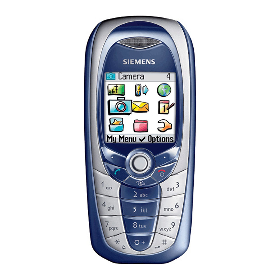
Siemens C65 Service Repair Documentation
Hide thumbs
Also See for C65:
- User manual (73 pages) ,
- User manual (139 pages) ,
- User manual (146 pages)
Table of Contents
Advertisement
Quick Links
Advertisement
Table of Contents

Summary of Contents for Siemens C65
- Page 1 Company Confidential Copyright 2003© Siemens AG Service Repair Documentation Level 2.5 - C65 Release Date Department Notes to change 01.06.2004 ICM MP CCQ GRM T New document Page Service Repair Documentation Release 1.0 Level 2.5 - C65...
- Page 2 General Test Instruction document (both documents are available in the Technical Support section of the C-market). Check at least weekly C-market for updates and consider all C65 related Customer Care Information C65 Partnumber on IMEI label: S30880-S7800-#xxx , while # may be any letter (A-Z) and xxx may be any number from 100, 101, 102..
-
Page 3: Table Of Contents
Company Confidential Copyright 2003© Siemens AG Table of Content C65 board layout ...........................4 Connector SIM Card Reader ......................5 Connector IO Jack.........................6 Connector Board to Board......................75 Connector Battery .........................8 IRDA Diode ...........................9 Connector Display ........................10 Connector Camera ........................11 Connector RF ..........................12 Joystick ............................13... -
Page 4: C65 Board Layout
Company Confidential Copyright 2003© Siemens AG 1 C65 board layout Jigs, Tools and Working materials for all described repairs: hot air blower soldering gun tweezers flux solder Joystick SW Connector Board to Board Connector Display Diode IRDA Connector SIM CARD READER... -
Page 5: Connector Sim Card Reader
Use soldering iron to remove defective component. Avoid excessive heat! Watch surrounding components! Resolder new component afterwards. E-commerce order number: L36334-Z97-C335 Soldering temperature: 240 - 255°C IRIS Diagnose Code: 43300 Interface/SIM Cardreader/Mechanical Damage Page Service Repair Documentation Release 1.0 Level 2.5 - C65... -
Page 6: Connector Io Jack
Use soldering iron to remove defective component. Avoid excessive heat! Watch surrounding components! Resolder new component afterwards. E-commerce order number: L36334-Z93-C303 Soldering temperature: 240 - 255°C IRIS Diagnose Code: 46100 Interface/Charging Connector/Mechanical Damage 47300 Interface/Data Interface/Mechanical Damage 4B100 Interface/Headset Connector/Mechanical Damage Page Service Repair Documentation Release 1.0 Level 2.5 - C65... -
Page 7: Connector Board To Board
E-commerce order number: L36334-Z97-C162 Soldering temperature: 240 - 255°C IRIS Diagnose Code: 32100 Keys / Main / No Function 32200 Keys / Main / Reduced Functionality 36000 Keys / Illumination Page Service Repair Documentation Release 1.0 Level 2.5 - C65... -
Page 8: Connector Battery
Use hot air blower to remove defective component. Avoid excessive heat! Watch surrounding components! Resolder new component afterwards. E-commerce order number: L36334-Z97-C336 Soldering temperature: 240 - 255°C IRIS Diagnose Code: 13000 Battery/Mechanical Damage Page Service Repair Documentation Release 1.0 Level 2.5 - C65... -
Page 9: Irda Diode
Resolder new component afterwards. E-commerce order number: L36197-F5008-F492 Soldering temperature: 240 - 255°C IRIS Diagnose Code: 41100 Interfaces / IRDA / No Function 41300 Interfaces / IRDA / Mechanical Damage Page Service Repair Documentation Release 1.0 Level 2.5 - C65... -
Page 10: Connector Display
Use soldering iron to remove defective component. Avoid excessive heat! Watch surrounding components! Resolder new component afterwards. E-commerce order number: L36334-Z97-C205 Soldering temperature: 240 - 255°C IRIS Diagnose Code: 21000 Display / Performance 22000 Display / Background Illumination Page Service Repair Documentation Release 1.0 Level 2.5 - C65... -
Page 11: Connector Camera
Use hot air blower to remove defective component. Avoid excessive heat! Watch surrounding components! Resolder new component afterwards. E-commerce order number: L36197-F5008-F341 Soldering temperature: 240 - 255°C IRIS Diagnose Code: 9B100 Functionality / Integrated Camera / No Function Page Service Repair Documentation Release 1.0 Level 2.5 - C65... -
Page 12: Connector Rf
83100 Radio / Dropped Calls / Int. Antenna 83200 Radio / Dropped Calls / Ext. Antenna 84100 Radio / Call Setup / Int. Antenna 84200 Radio / Call Setup / Ext. Antenna Page Service Repair Documentation Release 1.0 Level 2.5 - C65... -
Page 13: Joystick
Resolder new component afterwards. E-commerce order number: L36315-Z77-C218 Soldering temperature: 240 - 255°C IRIS Diagnose Code: 32100 Keys / Main / No Function 32200 Keys / Main / Reduced Functionality Page Service Repair Documentation Release 1.0 Level 2.5 - C65...


