
Related Manuals for Motorola APX 4000 2


Summary of Contents for Motorola APX 4000 2
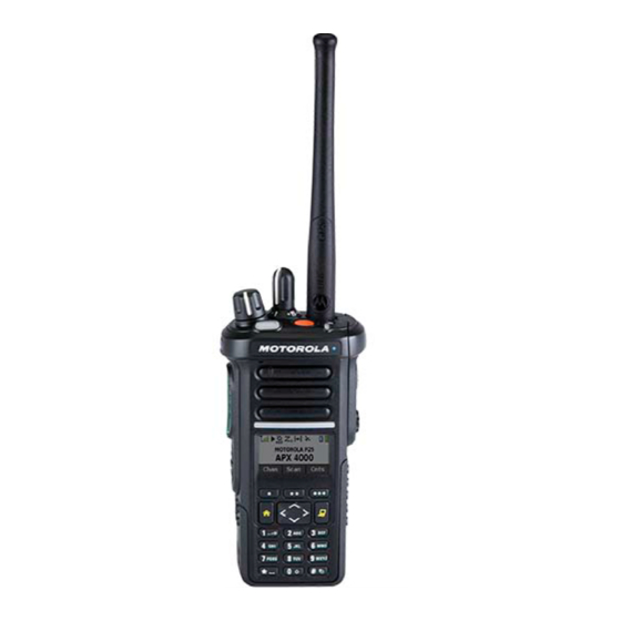
- Page 1 TWO-WAY RADIOS APX 4000 (2 KNOBS) MODEL 2 & MODEL 3 INTERACTIVE END USER TOOLKIT (IEUTK) Model 2 Model 3...
-
Page 2: Radio Parts And Controls
APX 4000 (2 KNOBS) RADIO PARTS AND CONTROLS MODEL 3 MODEL 2 Antenna Volume Knob 16-Position Channel Knob Top Light bar Top button Top (Orange) SCAN Button* EMERGENCY Speaker Push-to-Talk Microphone (PTT) Button Accessory Connector Side Button 2 NUISENSE DELETE Menu Select Main Display Buttons... -
Page 3: Charging The Battery
• DO NOT replace the battery in any area labeled “hazardous atmosphere”. • DO NOT discard batteries in a fire. The Motorola-approved battery shipped with your radio is uncharged. Prior to using a new battery, charge it for a minimum of 16 hours to ensure optimum capacity and performance. -
Page 4: Attaching/Removing The Battery
APX 4000 (2 KNOBS) PREPARING YOUR RADIO FOR USE Attaching/Removing the Battery Slide the battery into the radio’s frame until the bottom latch To remove the battery, turn the radio off. Lift up the latch then clicks into place. slide the battery down to remove the battery from the radio. -
Page 5: Attaching/Removing The Antenna
APX 4000 (2 KNOBS) PREPARING YOUR RADIO FOR USE Attaching/Removing the Antenna With the radio turned off, set the antenna in its receptacle and turn clockwise to attach it to the radio. To remove the antenna, turn the antenna counterclockwise. Make sure you turn off the radio first. - Page 6 APX 4000 (2 KNOBS) PREPARING YOUR RADIO FOR USE Attaching/Removing the Accessory Connector Cover The accessory connector is located on the antenna side of the radio. It is used to connect accessories to the radio. Hooked End Note: To prevent damage to the connector, shield it with the Accessory connector cover when not in use.
-
Page 7: Attaching/Removing The Belt Clip
APX 4000 (2 KNOBS) PREPARING YOUR RADIO FOR USE Attaching/Removing the Belt Clip Align the grooves of the belt clip with those of the radio and press upward until you hear a click. To remove the clip, use a flat bladed object to press the belt clip tab away from the radio. -
Page 8: Turning On/Off The Radio
APX 4000 (2 KNOBS) PREPARING YOUR RADIO FOR USE Turning on/off the Radio Rotate the On/Off/Volume Control Knob clockwise until you hear a click. On/Off/Volume If the power-up test is successful, you see the Home screen. Control Knob Note: If the power-up test is unsuccessful, you see Error XX/YY (XX/YY is an alphanumeric code). -
Page 9: Adjusting The Volume
APX 4000 (2 KNOBS) PREPARING YOUR RADIO FOR USE Adjusting the Volume To increase the volume, rotate the On/Off/Volume Control Knob clockwise. On/Off/Volume To decrease the volume, rotate the On/Off/Volume Control Control Knob Knob counterclockwise. CONTENTS < PREV NEXT >... -
Page 10: Accessing The Preprogrammed Functions
APX 4000 (2 KNOBS) IDENTIFYING RADIO CONTROLS Accessing the Preprogrammed Functions You can access various radio functions through one of the following ways: • A short or long press of the relevant programmable buttons. • Use the Menu Select Buttons ( Using the Menu Select Buttons The Menu Select Buttons allow to access the menu entries of features. - Page 11 APX 4000 (2 KNOBS) KNOBS, TOP AND SIDE BUTTONS – Channel Selects a channel. TOP CHANNEL CONTROL KNOB – Scan Toggles scan on or off. THE TOP SIDE BUTTON TURNS SCAN ON/OFF – Nuisance Delete Temporarily removes an unwanted channel, except for priority channels or the designated transmit channel, from the scan list.
- Page 12 APX 4000 (2 KNOBS) SOFT PROGRAMMABLE BUTTONS – Zone Select Allows selection from a list of zones. 5 ZONE TO CHOOSE FROM, MENU SELECT BUTTON. – Radio Profiles Allows for easy access to a set of preprogrammed visual and audio settings of the radio. THE LOUD OR DEFUALT PROFILE MIGHT BE USED, MENU SELECT BUTTON.
- Page 13 APX 4000 (2 KNOBS) OTHER FUNCTION PREPROGRAMMED IN TALKGROUPS Secure Transmission: SECURE OPERATION IS STRAPPED TO THE CHANNELS THAT WILL USE SECURE, NO NEED TO SELECT SECURE OR Talkaround/Direct : DIRECT CHANNELS ARE PREPROGRAMMED INTO THE RADIO, NO NEED TO SLEECT DIRECT MODE OR TALK AROUND –...
- Page 14 APX 4000 (2 KNOBS) IDENTIFYING RADIO CONTROLS Using the Navigation Buttons 4-Way Navigation Button Home Button Use this button to scroll up, down, left or right. Press and release one of the button to scroll from one entry button returns you to the Home (default) screen. In to the next one.
-
Page 15: Push-To-Talk (Ptt) Button
APX 4000 (2 KNOBS) IDENTIFYING RADIO CONTROLS Push-To-Talk (PTT) Button The PTT button on the side of the radio serves two basic purposes: • While a call is in progress, the PTT button allows the radio to transmit to other radios in the call. Press and hold down PTT button to talk. -
Page 16: Status Icons
APX 4000 (2 KNOBS) IDENTIFYING STATUS INDICATORS Status Icons Direct The 160 x 90 pixel front liquid crystal display (LCD) of the • On = Radio is currently configured for direct radio shows radio status, text entries, and menu entries. radio-to-radio communication (during The top display row contain color icons that indicate radio conventional operation only). - Page 17 APX 4000 (2 KNOBS) IDENTIFYING STATUS INDICATORS Top Light bar and LED Indicators The Top Light bar and LED indicators show the operational status of your radio. Top Light bar CONTENTS < PREV NEXT >...
- Page 18 APX 4000 (2 KNOBS) IDENTIFYING STATUS INDICATORS Top Light bar and LED Indicators LED Indications – Solid red Radio is transmitting. – Blinking red Radio is transmitting at low battery condition. – Rapidly blinking red Radio has failed the self test upon powering up or encountered a fatal error. –...
- Page 19 APX 4000 (2 KNOBS) IDENTIFYING STATUS INDICATORS Top Light bar and LED Indicators Top Light bar Indications This feature temporarily changes the color of the Top Lightbar and adds a color bar to the main display screen to help signal that a radio event has occurred.
-
Page 20: Intelligent Lighting Indicators
APX 4000 (2 KNOBS) IDENTIFYING STATUS INDICATORS Intelligent Lighting Indicators This feature temporary changes the radio’s display backlight color and the alert text background color to help signal that a radio event has occurred. Note: This feature must be preprogrammed by a qualified radio technician. Backlight and Bar Color Notification When... - Page 21 APX 4000 (2 KNOBS) IDENTIFYING STATUS INDICATORS Orange Emergency Alerts Critical Alerts CONTENTS < PREV NEXT >...
-
Page 22: Alert Tones
APX 4000 (2 KNOBS) IDENTIFYING STATUS INDICATORS Alert Tones An alert tone is a sound or group of sounds. Your radio uses alert tones to inform you of your radio’s conditions. The following table lists these tones and when they occur. You Hear Tone Name Heard... - Page 23 APX 4000 (2 KNOBS) IDENTIFYING STATUS INDICATORS You Hear Tone Name Heard Short, Valid Key-Press When correct key is pressed. Medium-Pitched Radio Self Test Pass When radio passes its power-up self test. Tone Priority Channel Received Play Emergency Alarm Entry When entering the emergency state.
-
Page 24: General Radio Operation
APX 4000 (2 KNOBS) GENERAL RADIO OPERATION Selecting a Zone A zone is a group of channels. Procedure: to Zone. Press the Menu Select button directly below Zone. to the required zone. Model 3 Use the keypad to enter the zone number. If the zone number entered is unprogrammed, the display shows Invalid entry. -
Page 25: Selecting A Radio Channel
APX 4000 (2 KNOBS) GENERAL RADIO OPERATION Selecting a Radio Channel A channel is a group of radio characteristics, such as transmit/receive frequency pairs. Procedure: [16-Position Select Knob] Turn the preprogrammed 16-Position Select Knob to the desired channel. CONTENTS <... -
Page 26: Receiving And Responding To A Radio Call
APX 4000 (2 KNOBS) GENERAL RADIO OPERATION Receiving and Responding to a Radio Call Once you have selected the required channel and/or zone, you can proceed to receive and respond to calls. The LED lights up solid red while the radio is transmitting. In conventional mode, the LED lights up solid yellow when the radio is receiving a transmission. - Page 27 APX 4000 (2 KNOBS) GENERAL RADIO OPERATION Receiving and Responding to a Radio Call Receiving and Responding to a Talkgroup Call To receive a call from a group of users, your radio must be configured as part of that talkgroup. 16-Position Channel Knob Procedure:...
-
Page 28: Making A Radio Call
APX 4000 (2 KNOBS) GENERAL RADIO OPERATION Making a Radio Call You can select a zone, channel, subscriber ID, or talkgroup by using: • The 16-Position Select Channel Knob. • A preprogrammed One Touch button • The Contacts list Note: If the feature inactivity timer is enabled, your radio automatically exits the feature when your radio is left idle long enough for the time to expire. - Page 29 APX 4000 (2 KNOBS) GENERAL RADIO OPERATION Making a Radio Call Making a Talkgroup Call To make a call to a group of users, your radio must be configured as part of that talkgroup. 16-Position Channel Knob Procedure: Volume Knob Turn the 16-Position Select Channel Knob to select the channel with the desired talkgroup.
-
Page 30: Scan Lists
APX 4000 (2 KNOBS) ADVANCED FEATURES Scan Lists Scan lists are created and assigned to individual channels/groups. Your radio scans for voice activity by cycling through the channel/group sequence specified in the scan list for the current channel/group. Your radio supports different types of Scan Lists: •... - Page 31 APX 4000 (2 KNOBS) ADVANCED FEATURES Scan Lists Viewing a Scan List Procedure: to ScnL. Press the Menu Select button directly below ScnL. to view the members on the list. Press to exit the current display and return to the Home screen.
- Page 32 APX 4000 (2 KNOBS) ADVANCED FEATURES Scan Lists Editing the Scan List [Menu] to ScnL. Press the Menu Select button directly below ScnL. The display shows the lists that can be changed. to the entry you want to edit. Press the Menu Select button directly below Sel to add and/ or change the priority of the currently displayed channel in the scan list.
- Page 33 APX 4000 (2 KNOBS) ADVANCED FEATURES Priority Status A Scan icon indicates that the current channel is in the scan list as a non-priority channel. The LED lights up solid green. A Priority-Two Channel Scan icon indicates that the current channel is in the scan list as the Priority-Two channel.
- Page 34 APX 4000 (2 KNOBS) ADVANCED FEATURES Scan Turning Scan On or Off This feature allows you to monitor traffic on different channels by scanning a preprogrammed list of channels. Procedure: [Preprogrammed Button] Press the preprogrammed Scan button to SCAN initiate or stop scan.
- Page 35 APX 4000 (2 KNOBS) ADVANCED FEATURES Scan Deleting a Nuisance Channel If a channel continually generates unwanted calls or noise (termed a “nuisance” channel), 16-Position Channel Knob you can temporarily remove the unwanted channel from the scan list. Volume Knob SCAN This capability does not apply to priority channels or the designated transmit channel.
- Page 36 APX 4000 (2 KNOBS) ADVANCED FEATURES Scan Restoring a Nuisance Channel Procedure: 16-Position Channel Knob To restore the deleted nuisance channel, do one of the following: Volume Knob • Top Side Turn the radio off and then turning it on (Select) again.
-
Page 37: Emergency Operation
APX 4000 (2 KNOBS) ADVANCED FEATURES Emergency Operation The Emergency feature is used to indicate a critical situation. If the Top (Orange) button is preprogrammed to send an emergency signal, this signal overrides any other communication over the selected channel. Your radio supports the following Emergency modes: •... - Page 38 APX 4000 (2 KNOBS) ADVANCED FEATURES Emergency Operation Sending an Emergency Alarm When you receive the dispatcher’s acknowledgment, the This feature allows you to send a data transmission, which identifies the radio sending the emergency, to the dispatcher. display shows Ack received. You hear four tones, the alarm ends, and the radio exits Note: Emergency button press timer by default is set to 1 the Emergency Alarm mode.
- Page 39 APX 4000 (2 KNOBS) ADVANCED FEATURES Emergency Operation Sending an Emergency Alarm This feature allows you to send an Emergency Alarm to EMERGENCY another radio without any audio or visual indicators. BUTTON Procedure: Volume Knob Press the preprogrammed Emergency button. SCAN The display shows no changes, the LED does not light up, and you hear no tones.
-
Page 40: Tactical Public Safety(Tps)
APX 4000 (2 KNOBS) ADVANCED FEATURES Tactical Public Safety(TPS) Using TPS Normal Transmission TPS enabled the users of a group to identify a transmission starts and ends clearly by displaying the caller’s name or ID on the radio display. Procedure: At TPS Zone Channel Press PTT button to transmit. - Page 41 APX 4000 (2 KNOBS) ADVANCED FEATURES Tactical Public Safety(TPS) Using TPS Emergency Transmission – Emergency Beacon During Emergency if the TPS radio user pushes the Emergency button, the radio sounds a Beacon at the maximum volume of the radio at radio’s internal speaker and it is not adjustable. This beacon goes to silent when user presses the PTT button for voice transmission.
-
Page 42: Trunking System Controls
APX 4000 (2 KNOBS) ADVANCED FEATURES Trunking System Controls Using the Fail-soft System The fail-soft system ensures continuous radio communications during a trunked system failure. If a trunking system fails completely, the radio goes into fail- Model 2 Model 3 soft operation and automatically switches to its fail-soft channel. - Page 43 APX 4000 (2 KNOBS) ADVANCED FEATURES Trunking System Controls Going Out of Range When your radio goes out of the range of the system, it can no longer lock onto a control channel. Procedure: You hear a low-pitched tone. AND/OR The display shows the currently selected zone/channel combination and Out of range.
- Page 44 APX 4000 (2 KNOBS) ADVANCED FEATURES Trunking System Controls Using the Site Trunking Feature If the zone controller loses communication with any site, that site reverts to site trunking. The display shows the currently selected zone/channel Model 2 Model 3 combination and Site trunking.
- Page 45 [Menu] to BT. This feature allows your radio to extend its functionality by connecting to external proprietary Motorola Accessories. Press the Menu Select button directly below BT to access the Bluetooth feature screen. The default setting for Bluetooth-enabled radio is Bluetooth to Status.
-
Page 46: Voice Announcement
APX 4000 (2 KNOBS) ADVANCED FEATURES Voice Announcement This feature enables the radio to audibly indicate the current Note: Voice announcements support certain number of zone- feature mode, Zone or Channel the user has just assigned. channel, but not all. This audio indicator can be customized per customer Seek advice from your dealer or qualified technician for requirements. -
Page 47: Selecting A Radio Profile
APX 4000 (2 KNOBS) UTILITIES Selecting a Radio Profile This feature allows you to manually switch the visual and audio settings of the radio. The display, backlight, alert tones, [Menu] and audio settings are defined according to the to Prfl. preprogrammed radio settings of each radio profile. -
Page 48: Controlling The Display Backlight
APX 4000 (2 KNOBS) UTILITIES Controlling the Display Backlight You can enable or disable the radio’s display backlight as Note: The backlight remains on for a preprogrammed time needed, if poor light conditions make the display or keypad before it automatically turns off completely or returns to the difficult to read. -
Page 49: Using The Time-Out Timer
APX 4000 (2 KNOBS) UTILITIES Using the Time-Out Timer This feature turns off your radio’s transmitter. You cannot Press the PTT button to re-transmit. transmit longer than the preset timer setting. The time-out timer restarts and the LED lights up solid red. If you attempt to do so, the radio automatically stops your transmission, and you hear a talk-prohibit tone. -
Page 50: Setting The Time And Date
APX 4000 (2 KNOBS) UTILITIES Setting the Time and Date You can set the time and date for your radio. to change the selected item. Settings: one or more times to move to an item you wish to change. •... -
Page 51: Using The Digital Ptt Id Feature
APX 4000 (2 KNOBS) UTILITIES Using the Digital PTT ID Feature This feature allows you to see the radio ID (number) of the radio from whom you are currently receiving a transmission. 16-Position This ID, consisting up to a maximum of eight characters, can Channel Knob be viewed by both the receiving radio and the dispatcher. - Page 52 APX 4000 (2 KNOBS) UTILITIES IMPRES™ Battery Annunciator This feature displays the current capacity and charges cycles To access battery info screen: of your battery when a IMPRES Battery is powering your radio. Procedure: This feature must be enabled in your radio to see the to Batt.