Table of Contents
Advertisement
Quick Links
Advertisement
Table of Contents

Related Manuals for ABB ACS880-87CC


Summary of Contents for ABB ACS880-87CC
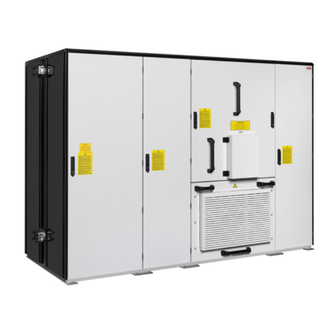
- Page 1 — ABB WIND TURBINE CONVERTERS ACS880-87CC wind turbine converters Hardware manual...
- Page 3 ACS880-87CC wind turbine converters Hardware manual Table of contents 1. Safety instructions 4. Mechanical installation 6. Electrical installation 3AXD50000466948 Rev B Original instructions EFFECTIVE: 2021-06-07...
-
Page 5: Table Of Contents
Table of contents 5 Table of contents 1 Safety instructions Contents of this chapter ................Use of warnings and notes ............... General safety in installation, start-up and maintenance ........Electrical safety in installation, start-up and maintenance ........Precautions before electrical work ............Additional instructions and notes ............. - Page 6 6 Table of contents 4 Mechanical installation Contents of this chapter ................Safety instructions ................. Checklist before mechanical installation ............Moving the converter package ..............Moving the converter package by fork-lift ........... Moving the converter on rollers .............. Unpacking ................... Lifting the converter ................
- Page 7 Table of contents 7 Protecting the contacts of relay outputs ............6 Electrical installation Contents of this chapter ................Checking the insulation of the assembly ............Converter ..................Grid cable ..................Generator stator and generator cable ............Connecting the grid cables ............... Connection diagram ................
- Page 8 8 Table of contents 9 Technical data Contents of this chapter ................Ratings ....................Definitions ..................Derating ..................Ambient temperature derating ............Altitude derating ................Type equivalence table ................Fuses ....................Main circuit AC fuses ................Main circuit DC fuses ................Fuses for the voltage measurement board BAMU ........
- Page 9 Table of contents 9 Layout and connections ................Connector data ..................11 BCU-x5 control unit Contents of this chapter ................General ....................BCU control unit ................Layout and connections ................Connector data ..................12 Dimension drawings Contents of this chapter ................13 Cooling and heating Contents of this chapter ................
-
Page 11: Safety Instructions
Safety instructions 11 Safety instructions Contents of this chapter This chapter contains the safety instructions which you must obey when you install and operate the converter, and do maintenance on the converter. If you ignore the safety instructions, injury, death or damage can occur to the converter, the generator or other adjoining equipment. -
Page 12: General Safety In Installation, Start-Up And Maintenance
12 Safety instructions General safety in installation, start-up and maintenance These instructions are for all personnel that install the converter and do maintenance work on it. - Page 13 Safety instructions 13 WARNING! Obey these instructions. If you ignore them, injury or death, or damage to the equipment can occur. • Use safety shoes with a metal toe cap. Use protective gloves. • Use protective eyewear when working with the liquid cooling system. •...
-
Page 14: Electrical Safety In Installation, Start-Up And Maintenance
14 Safety instructions Electrical safety in installation, start-up and maintenance Precautions before electrical work ■ These instructions are for the qualified electricians who do work on the converter, generator cable or generator. WARNING! Obey these instructions. If you ignore them, injury or death, or damage to the equipment can occur. -
Page 15: Additional Instructions And Notes
Safety instructions 15 6. Install temporary grounding as required by the local regulations. 7. Ask the person in control of the electrical installation work for a permit to work. Additional instructions and notes ■ WARNING! Obey these instructions. If you ignore them, injury or death, or damage to the equipment can occur. -
Page 16: Opening And Disconnecting The Main Circuit Breaker
16 Safety instructions Opening and disconnecting the main circuit breaker ■ These instructions are for the qualified electricians who do work on the converter, generator cable or generator. WARNING! If you are not a qualified electrician, do not proceed or do any installation or maintenance work. - Page 17 Safety instructions 17...
-
Page 18: Disconnecting The Charging Circuit From The Main Circuit
18 Safety instructions Disconnecting the charging circuit from the main circuit ■ WARNING! If you are not a qualified electrician, do not proceed. 1. Make sure that you have opened the main circuit breaker (Q1). See section Opening and disconnecting the main circuit breaker (page 16). -
Page 19: Disconnecting The Auxiliary Power Supply
Safety instructions 19 Disconnecting the auxiliary power supply ■ WARNING! If you are not a qualified electrician, do not proceed. 1. Make sure that you have opened the main circuit breaker (Q1). See section Opening and disconnecting the main circuit breaker (page 16). -
Page 20: Grounding
20 Safety instructions Grounding ■ These instructions are intended for all who are responsible for the grounding of the converter. WARNING! Obey these instructions. If you ignore them, injury or death, or damage to the equipment can occur, and electromagnetic interference can increase. •... -
Page 21: Work On The Liquid Cooling System
Safety instructions 21 Work on the liquid cooling system These instructions are intended for all who are responsible for installation and maintenance work of the liquid cooling system of the converter. WARNING! Obey these instructions. If you ignore them, injury or damage to the equipment can occur. -
Page 23: Introduction To The Manual
Introduction to the manual 23 Introduction to the manual Contents of this chapter This chapter describes the intended audience and contents of the manual. It also contains a flowchart of steps in checking the delivery, installing and commissioning the wind turbine converter. -
Page 24: Quick Installation, Commissioning And Operation Flowchart
24 Introduction to the manual Quick installation, commissioning and operation flowchart Task Plan the installation. Check: ambient conditions, ratings, Technical data (page 95) required external cooling circuit arrangements, compat- Planning the electrical installation (page 53) ibility of the generator, power cable connection, etc. Option manuals (if optional equipment is included) Select the cables. -
Page 25: Terms And Abbreviations
Introduction to the manual 25 Terms and abbreviations Term Description Auxiliary control unit. Contains control electronics, auxiliary voltage circuitry, etc. BAMU Auxiliary measurement unit BCON Type of control board Type of control unit Control unit The part in which the control program runs. Converter Converts direct current and voltage to alternating current and voltage, or vice versa.) Converter module... -
Page 26: Related Documents
26 Introduction to the manual Related documents Name Code General manuals Drive/converter/inverter safety instructions 3AXD50000037978 ACS880-87CC wind turbine converters hardware manual 3AXD50000466948 ACS880-77LC/-87LC/-87CC wind turbine converters with WTA firmware manual 3AXD50000038874 ACS880-77LC/-87LC/-87CC wind turbine converters firmware manual 3AUA0000130879 ACS880-77LC/-87LC/-87CC wind turbine converters system description... -
Page 27: Operation Principle And Hardware Description
This chapter describes the operation principle and the construction of the wind turbine converter. Operation principle The ACS880-87CC is a four-quadrant, cabinet-mounted combined-cooled converter intended for full power conversion turbines with an induction generator or a permanent magnet generator. The converter is connected between the generator stator and the grid. The converter can be installed up in the nacelle or down on the ground level. -
Page 28: Generator Control
28 Operation principle and hardware description Generator control The generator power flows through the generator-side converter to the converter intermediate DC circuit. The generator control is based on the Direct torque control (DTC) method. Two phase currents and intermediate DC circuit voltage are measured and used for the control. The third phase current is measured for ground fault protection. -
Page 29: Overview Diagram Of The Wind Turbine Converter
Operation principle and hardware description 29 Overview diagram of the wind turbine converter An example single-line diagram of the wind turbine converter is shown below. Single converter ■... -
Page 30: Parallel Converters
30 Operation principle and hardware description Parallel converters ■... -
Page 31: Layout Drawing
Operation principle and hardware description 31 Layout drawing Layout of the wind turbine converter is shown below. Front view Description Generator-side converter cubicle Main breaker cubicle Space for cooling unit Generator cable terminals [U2, V2, W2] Generator-side converter modules DC fuses Charging circuit switch [Q10] Auxiliary voltage switch [Q2] Charging contactor [Q6]... - Page 32 32 Operation principle and hardware description Back view Description LCL filter cubicle Grid-side converter cubicle LCL filter components (inductors are behind the capacitors) Cooling fans of the LCL filter cubicle Grid-side converter AC fuses Grid-side converter modules Grid-side converter DC fuses Space reservation for an additional grid-side converter module Lifting lugs Coolant connection of the cooling unit (outlet pipe)
- Page 33 Operation principle and hardware description 33 End view Description Auxiliary control cubicle Control cable terminals for customer connections BAMU measuring unit BCU-22 control unit BCU-15 control unit S500 I/O modules Heater of the auxiliary control cubicle...
-
Page 34: Overview Of Power And Control Connections
34 Operation principle and hardware description Overview of power and control connections The diagram shows the power connections and internal control interfaces of the wind turbine converter. See also section Circuit boards (page 36). The option module slots on the control unit are reserved for internal use and communication. -
Page 35: Parallel Converters
Operation principle and hardware description 35 Parallel converters ■ S500 S500 CI581-CN AX522 XCAN CH0 … CH3 BCON BCON Description Slots 1…3 RDCO (slot 4) BCU-x5 control unit BCU-x2 control unit External control via Ethernet and selected fieldbus (optional and customer-specified). Both BCU control units are connected to Ethernet switch. -
Page 36: Circuit Boards
36 Operation principle and hardware description Circuit boards These example diagrams show the interconnections between the circuit boards of the converter. For further details, see the delivery-specific circuit diagrams. For information on the BCU control units, see chapters BCU-x2 control unit BCU-x5 control unit. -
Page 37: Parallel Converters
Operation principle and hardware description 37 Parallel converters ■... - Page 38 38 Operation principle and hardware description...
-
Page 39: Bamu Board
The type designation label includes ratings, valid markings, type code and serial number of the converter. Each converter module is also individually labeled. Typical labels are shown below. Single converter ■ ACS880-87CC-2500A/2400A-7+B052+C143-C171+ F276+G335+G396+K473+P902+P955+R700 MADE IN ESTONIA Grid U1 3~ 690 VAC... -
Page 40: Parallel Converters
40 Operation principle and hardware description Parallel converters ■ Description Serial number. The first digit of the serial number refers to the manufacturing plant. The next four digits refer to the converter’s manufacturing year and week, respectively. The remaining digits complete the serial number so that there are no two converters with the same number. -
Page 41: Type Designation Key
Ratings of the converter Number and frame size of the converter modules. In the upper label for the ACS880-87CC converter, there are fivegenerator-side converter modules, three grid-side converter modules, and the frame size is R9iLC. In the lower label for converter module, the frame size of the module is R9iLC. -
Page 42: Basic Code
42 Operation principle and hardware description Basic code ■ Digit no. Name/Description Alternatives Description 1…6 Product series ACS880 ACS880 product series 8…11 Construction 87CC Cabinet-installed combined-cooled wind turbine converter 13…23 Size See the ratings. Generator-side converter current rating / Grid-side converter current rating Voltage rating 7 –... - Page 43 Operation principle and hardware description 43 Code Description I/O options L500 FIO-11 analog I/O extension module L501 FIO-01 digital I/O extension module L502 FEN-31 HTL incremental encoder interface module L503 DDCS communication 3 L504 Additional I/O - terminal block L505 Thermistor relay L506 Pt100 relay...
-
Page 45: Mechanical Installation
Mechanical installation 45 Mechanical installation Contents of this chapter This chapter describes the mechanical installation procedure of the wind turbine converter. Safety instructions See the safety instructions. -
Page 46: Checklist Before Mechanical Installation
•Pozidriv and Torx (2.5 … 6 mm, 0.98 … 0.2 in) screwdrivers for the tightening of the frame screws (Screws needed for fastening the cabling boxes and other accessories delivered by ABB are included in the delivery. They are inside the cabinet. The delivery does not contain screws or tools to install the cabinet to the floor.) -
Page 47: Moving The Converter Package
Mechanical installation 47 Moving the converter package Moving the converter package by fork-lift ■ WARNING! Only use a heavy duty forklift that can carry the weight of the converter. • Make sure that the reach of the fork lift is long enough. The package is wide and the center of gravity is far from the edges. -
Page 48: Unpacking
4. Detach the converter from its platform, lift the converter and remove the platform. Lifting the converter Obey these instructions when there are no ABB lift adapter bars in use: 1. Attach the lifting slings to holes of the lifting bars (a). Use long enough slings. See the minimum lifting angle in the figure below. - Page 49 Mechanical installation 49...
-
Page 50: Placing The Converter
50 Mechanical installation Placing the converter The cabinet can be placed into its final position with an iron bar and a wooden piece at the bottom edge of the cabinet. Place the wooden piece carefully to avoid damage to the cabinet frame. -
Page 51: Fastening The Cabinet To The Floor
Mechanical installation 51 Fastening the cabinet to the floor Bolt the converter to the floor through the holes in each flat bar at the base of the cabinet using M12 screws. We do not recommend welding (see section Electric welding (page 51)). - Page 52 52 Mechanical installation • Weld only the flat bar under the cabinet, never the cabinet frame itself. • Clamp the welding electrode onto the flat bar about to be welded or to the next flat bar of the cabinet (within 0.5 meters (1’6”) of the welding point). WARNING! If the welding return wire is connected improperly, the welding circuit may damage electronic circuits in the cabinet.
-
Page 53: Planning The Electrical Installation
ABB does not assume any liability whatsoever for any installation which breaches the local laws and/or other regulations. Furthermore, if the recommendations given by ABB are not followed, the converter may experience problems that the warranty does not cover. -
Page 54: Checking The Compatibility Of The Generator And The Converter
ABB power modules are equipped with internal du/dt filters which reduce the bearing currents and stress on the generator insulations. In addition, a common mode filter can be used to reduce such stresses on the generator-side. -
Page 55: Selecting The Power Cables
Planning the electrical installation 55 • du/dt filter protects generator insulation system and reduces bearing currents • common mode filter mainly reduces bearing currents (option). To avoid damage to generator bearings, the cables must be selected and installed according to the instructions given in this manual. In addition, insulated N-end (non-converter end) bearings must be used. -
Page 56: Typical Power Cable Sizes
Typical power cable sizes ■ CE cables Generator cables Converter type Cable type Conductor type Total quantity of parallel conductors per phase ACS880-87CC- 300 mm 240 mm 185 mm 5200A/4800A-7 Copper 2×6 2×7 2×8... -
Page 57: Ul Cables
Planning the electrical installation 57 UL cables Generator cables Converter type Cable type Conductor Total quantity of parallel conductors per phase type ACS880-87CC- 1000 kcmil 500 kcmil 400 kcmil 350 kcmil 5200A/4800A-7 Copper 2×10 2×14 2×15 2×17 5160A/4800A-7 Copper 2×10 2×14... -
Page 58: Not Allowed Power Cable Types
58 Planning the electrical installation Not allowed power cable types A four-conductor system (three phase conductors and a PE conductor in a PVC conduit) Corrugated cable with three phase conductors and a protective conductor or cable in EMT conduit A well-shielded (Al/Cu shield) four-conductor system (three phase conductors and a PE conductor or four conductors) Symmetrical shielded cable with individual shields for each phase conductor is not allowed on any cable size for grid and generator cabling. -
Page 59: Additional Us And Canada Requirements
Planning the electrical installation 59 Layout Description Multicore cabling (recommended). See subsection Alternative power cable types for the possible con- structions of the PE (protective earth/ground). Single core cables in trefoil (preferable single core cabling option). Single core cables laid flat. Additional US and Canada requirements ■... -
Page 60: Relay Cable
Never mix 24 V DC and 115 / 230 V AC signals in the same cable. Relay cable ■ The cable type with braided metallic screen (for example, ÖLFLEX from Lapp Kabel, Germany) has been tested and approved by ABB. -
Page 61: Routing The Cables
Planning the electrical installation 61 Routing the cables Route the generator cable away from other cable routes. It is recommended that the generator cable, grid cable and control cables are installed on separate trays. Avoid long parallel runs of generator cables with other cables in order to decrease electromagnetic interference caused by the rapid changes in the converter output voltage. -
Page 62: Control Cable Ducts
62 Planning the electrical installation Control cable ducts ■ 230 V AC 24 V DC (120 V AC) 230 V AC 24 V DC (120 V AC) Picture on the left: Lead 24 V and 230/120 V control cables in separate ducts into the inside of the cabinet. -
Page 63: Protecting The Converter Against Ground Faults In The Converter Or Grid Cable
(This is not a personal safety or a fire protection feature.) You can disable both ground fault protective functions (not recommended); refer to the firmware manual. Implementing the emergency stop function For further information, contact your local ABB representative. Implementing the grid fault ride-through function See the firmware manual. - Page 64 64 Planning the electrical installation 230 V AC 230 V AC + 24 V DC Relay outputs Varistor RC filter Diode...
-
Page 65: Electrical Installation
Electrical installation 65 Electrical installation Contents of this chapter This chapter describes the electrical installation procedure of the wind turbine converter. WARNING! Only qualified electricians are allowed to carry out the work described in this chapter. Read the complete safety instructions of the converter. If you ignore them, injury or death, or damage to the equipment can occur. -
Page 66: Generator Stator And Generator Cable
1000 V DC. The insulation resistance of an ABB generator must exceed 100 Mohm (reference value at 25 °C (77 °F)). For the insulation resistance of other generators, please consult the manufacturer’s instructions. -
Page 67: Connection Procedure
Electrical installation 67 Connection procedure ■ WARNING! See and obey the safety instructions of the converter. If you ignore them, injury or death, or damage to the equipment can occur. WARNING! Apply grease to stripped aluminum conductors before attaching them to non-coated aluminum cable lugs. -
Page 68: Connecting The Generator Cables
68 Electrical installation Connecting the generator cables Connection diagram ■ Connection procedure ■ WARNING! See and obey the safety instructions of the converter. If you ignore them, injury or death, or damage to the equipment can occur. WARNING! Apply grease to stripped aluminum conductors before attaching them to non-coated aluminum cable lugs. - Page 69 Electrical installation 69 4. When shielded cable is used: • Lead the cables into the inside of the cubicle. Ground a shielded cable 360° at the lead-through with an EMC cable gland (to be supplied by the customer). • Connect the cables as follows: •...
- Page 70 70 Electrical installation...
-
Page 71: Connecting The External Power Supply Cable For The Auxiliary Circuit
Electrical installation 71 Connecting the external power supply cable for the auxiliary circuit Customer connection for the auxiliary power output (X11) is located on the cabinet wall. Connector X11 on the cabinet wall... -
Page 72: Connecting The Control Cables
72 Electrical installation Connecting the control cables Control cable connectors are located in the control cubicle and on the cabinet roof (see the layout drawings). See the circuit diagrams delivered with the converter. Control connections in the control cubicle Connector Description Customer connection for 400 V AC non-UPS auxiliary power supply Customer connection for 230 V AC UPS auxiliary power supply... -
Page 73: Installation Checklist
Installation checklist 73 Installation checklist Contents of this chapter This chapter contains instructions for checking the installation of the wind turbine converter. Before you start Check the mechanical and electrical installation of the converter before start-up. Go through the checklist together with another person. WARNING! Only qualified electricians are allowed to carry out the work described below. -
Page 74: Checklist
74 Installation checklist Checklist Make sure that … The ambient operating conditions meet the specifications given in the technical data. The converter has been fixed properly on an even, horizontal and non-flammable floor and if necessary due to vibration etc, also from top to the wall or roof. The cooling circuit joints are tight. -
Page 75: Maintenance
Maintenance Contents of this chapter This chapter contains preventive maintenance intervals and instructions. Maintenance intervals The table below shows the maintenance tasks which can be done by the end user. For more information, consult your local ABB Service representative (www.abb.com/searchchannels). - Page 76 Performance of on/off-site work (commissioning, tests, measurements or other work) Replacement Maintenance and component replacement intervals are based on the assumption that the equipment is operated within the specified ratings and ambient conditions. ABB recommends annual inspections to ensure the highest reliability and optimum performance.
-
Page 77: Maintenance Timers And Counters
Note 2: The maintenance schedule of the main circuit breaker is according to maximum 1,000 operations of the breaker per each year. Replacement after 10000 operations. For more information, refer to the maintenance manual of the ABB SACE breaker. Maintenance timers and counters The control program has maintenance timers and counters that can be configured to generate a warning when a pre-defined limit is reached. -
Page 78: Cleaning The Door Air Inlets And Outlets (Auxiliary Control Cubicle)
78 Maintenance Cleaning the door air inlets and outlets (auxiliary control cubicle) ■ Check the dustiness of the air inlet meshes. If the dust cannot be removed by vacuum cleaning from outside through the grating holes with a small nozzle, proceed as follows: 1. -
Page 79: Fans
For resetting the running time after a fan replacement, contact ABB. Replacement fans are available from ABB. Do not use other than ABB specified spare parts. All the fans in the converter are of the same type. - Page 80 80 Maintenance Air flow direction is towards the converter module.
-
Page 81: Replacing The Fan Of The Main Breaker Cubicle
Maintenance 81 Replacing the fan of the main breaker cubicle ■ WARNING! Only qualified electricians are allowed to do this work. Read the complete safety instructions of the converter. If you ignore the instructions, physical injury, death, or damage to the equipment can occur. Disconnect the converter from the all power sources and make sure it is safe to start the work. -
Page 82: Replacing The Cooling Fan Of The Auxiliary Control Cubicle
82 Maintenance Replacing the cooling fan of the auxiliary control cubicle ■ WARNING! Only qualified electricians are allowed to do this work. Read the complete safety instructions of the converter. If you ignore the instructions, physical injury, death, or damage to the equipment can occur. 1. -
Page 83: Replacing The Cooling Fan Of The Lcl Filter Cubicle
Maintenance 83 Replacing the cooling fan of the LCL filter cubicle ■ WARNING! Only qualified electricians are allowed to do this work. Read the complete safety instructions of the converter. If you ignore the instructions, physical injury, death, or damage to the equipment can occur. 1. -
Page 84: Fuses
84 Maintenance Fuses Replacing the DC fuses ■ WARNING! Only qualified electricians are allowed to do this work. Read the complete safety instructions of the converter. If you ignore the instructions, physical injury, death, or damage to the equipment can occur. 1. -
Page 85: Replacing The Ac Fuses
Maintenance 85 Replacing the AC fuses ■ WARNING! Only qualified electricians are allowed to do this work. Read the complete safety instructions of the converter. If you ignore the instructions, physical injury, death, or damage to the equipment can occur. 1. -
Page 86: Converter Module
86 Maintenance Converter module Replacing the converter module ■ WARNING! Only qualified electricians are allowed to do this work. Read the complete safety instructions of the converter. If you ignore the instructions, physical injury, death, or damage to the equipment can occur. WARNING! If you ignore the following instructions, physical injury, death, or damage to the equipment can occur:... - Page 87 Maintenance 87 6. Unplug the fiber optic cables and X50 connectors. Carefully place the cables on top of the fan. 7. Remove the pipe clamps from top tubes. 8. Open top liquid connection nut with 30 mm wrench. Pull the pipe upwards to release it.
- Page 88 88 Maintenance 9. Open two module support bolts from top. 10. Open bottom liquid connection with 30 mm wrench. Pull the pipe downwards to release 11. Remove the module bottom support by opening 3 pcs of M6 screws and 2 pcs of M8 screws.
- Page 89 Maintenance 89 14. Open the installation stand (optional) and place it in front of the module.
- Page 90 90 Maintenance 15. Install 3 pcs of M6 Taptite® screws (removed earlier) to secure the installation stand. Tightening torque is 5 N·m (3.7 lbf·ft).
- Page 91 Maintenance 91 16. Insert M8 bolt to the hole on the top part of the module and turn it clockwise. This will help in pushing the module out. It also helps in pulling simultaneously from the handle while turning the screw. 17.
-
Page 92: Capacitors
Capacitor failure is usually followed by the converter module and module fuse failure, or a fault trip. Contact ABB if capacitor failure is suspected. Replacements are available from ABB. Do not use other than ABB specified spare parts. -
Page 93: Replacement Illustration
2. Insert the new card in reverse order. Tightening torque for fastening screw is 0.7 N·m (0.5 lbf·ft). Repeat the replacement procedure for other BCU control unit if needed. Replacement illustration ■ Main circuit breaker For ABB-SACE main circuit breaker maintenance, refer to the manufacturer’s instructions (1SDH001000R0002). -
Page 95: Technical Data
Technical data 95 Technical data Contents of this chapter This chapter contains the technical data of the ACS880-87CC. Ratings Generator-side converter Grid-side converter ratings ratings Converter type Cos phi ACS880-87CC- grid = 690 V 5200A/4800A-7 5345 5200 5163 4800 5737... -
Page 96: Derating
1 °C (1.8 °F) for every 100 m (328 ft). Derating is allowed only on maximum continuous current for grid and generator. If the installation site is located higher than 2000 m (6562 ft) above sea level, contact your local ABB representative. Type equivalence table... -
Page 97: Fuses
Technical data 97 Fuses Main circuit AC fuses ■ AC fuses Converter type Type ACS880-87CC- A rms = 690 V 5200A/4800A-7 Bussmann 170M6416 1250 2×9 5160A/4800A-7 Bussmann 170M6416 1250 2×9 6880A/5500A-7 Bussmann 170M6416 1250 2×12 3AXD10000011539 Main circuit DC fuses ■... -
Page 98: Losses, Cooling Data And Noise
For free space requirements, see the dimension drawings. Losses, cooling data and noise Losses Cooling data Liquid Coolant Mass flow Pressure Noise Converter type quantity loss (tolerance ACS880-87CC- -2%… +20%) l/min = 690 V 5200A/4800A-7 2×23 < 90 5160A/4800A-7 2×23 < 90 6880A/5500A-7 2×23 < 90... -
Page 99: Grid Specification
Total harmonic current distortion (n = 2…40) < 5%. Total harmonic voltage distortion (n = 2…40) < 5%, when R ≥ 7. Requirements for the grid connection For applicable grid codes, contact your local ABB representative. Generator connection data Generator types AC induction generators, permanent magnet generators Voltage (U 0…110% U... -
Page 100: Efficiency
1) Condensation and/or formation of ice inside the converter cabinet is not allowed in any operational circumstances. 2) ABB additional extension to ambient surrounding temperature, outside the cabinet, -30 °C…55 °C (-22 °F…131 °F). See also the instructions for ambient temperature derating. -
Page 101: Ambient Conditions
Technical data 101 Ambient conditions Environmental limits for the converter are given below. The converter must be used in a heated, indoor controlled environment. Operation installed for Storage in protective Transportation in protect- stationary use package ive package Installation site altitude 0 …... -
Page 102: Materials
Aluminum, acid-fast stainless steel, PA pipes Air filters (door) IP54 Cassette filter: 292 × 288 × 47 mm (ABB code: 64719998) IP42 filter (Air-Tex G-150): 5158 × 520 × 12 mm (ABB code: 64665324) Fire safety of materials Insulating materials and non-metallic items: Mostly self-extinctive... -
Page 103: Applicable Standards
Technical data 103 Applicable standards The converter complies with the standards below. The compliance with the European Low Voltage Directive is verified according to standards EN 61800-5-1. Safety of machinery. Electrical equipment of machines. Part 1: General require- •EN 60204-1:2006 + ments. -
Page 104: Eac (Eurasian Conformity) Marking
Equipment (victim) 2. An EMC plan for preventing disturbances is drawn up for the installation. A template is available from the local ABB representative. 3. The generator and control cables are selected as specified in the hardware manual. 4. The converter is installed according to the instructions given in the hardware manual. -
Page 105: Etl Marking
Notwithstanding any other provision to the contrary and regardless whether the contract is terminated or not, ABB and its affiliates are under no circumstances not liable for damages... - Page 106 106 Technical data and/or losses related to such security breaches, any unauthorized access, interference, intrusion, leakage and/or theft of data or information.
-
Page 107: Bcu-X2 Control Unit
This chapter describes the layout and connections of the BCU-x2 control unit and contains the specifications of the inputs and outputs of the control unit. For the actual connections of the control units used in the ACS880-87CC converter, see the circuit diagrams delivered with the converter. -
Page 108: Layout And Connections
108 BCU-x2 control unit Layout and connections Description I/O terminals SLOT 1 I/O extension, encoder interface or fieldbus adapter module connection. (This is the sole location for an FDPI-02 diagnostics and panel interface.) SLOT 2 I/O extension, encoder interface or fieldbus adapter module connection SLOT 3 I/O extension, encoder interface or fieldbus... - Page 109 BCU-x2 control unit 109 Description Analog inputs Analog outputs Digital inputs, Digital input interlock (DIIL) XRO3 XD24 XPOW XDIO Digital input/outputs XD2D Drive-to-drive link XRO2 XD24 +24 V output (for digital inputs) XDIO XETH Ethernet port XPOW External power input XRO1 XRO1 Relay output RO1...
-
Page 110: Connector Data
110 BCU-x2 control unit Connector data Power supply (XPOW) Connector pitch 5 mm, wire size 2.5 mm 24 V (±10%) DC, 2 A External power input. Two supplies can be connected to BCU for redundancy. Relay outputs RO1…RO3 Connector pitch 5 mm, wire size 2.5 mm (XRO1…XRO3) 250 V AC / 30 V DC, 2 A Protected by varistors... - Page 111 BCU-x2 control unit 111 Analog outputs AO1 and AO2 (XAO) Connector pitch 5 mm, wire size 2.5 mm 0…20 mA, R < 500 ohm load Frequency range: 0…500 Hz Resolution: 11 bit + sign bit Inaccuracy: 2% of full scale range XD2D connector Connector pitch 5 mm, wire size 2.5 mm Physical layer: RS-485...
-
Page 113: Bcu-X5 Control Unit Contents Of This Chapter
This chapter describes the layout and connections of the BCU-x5 control unit and contains the specifications of the inputs and outputs of the control unit. For the actual connections of the control units used in the ACS880-87CC converter, see the circuit diagrams delivered with the converter. -
Page 114: Layout And Connections
114 BCU-x5 control unit Layout and connections Description I/O terminals SLOT 1 I/O extension, encoder interface or fieldbus adapter module connection. (This is the sole location for an FDPI-02 diagnostics and panel interface.) SLOT 2 I/O extension, encoder interface or fieldbus adapter module connection SLOT 3 I/O extension, encoder interface or fieldbus... - Page 115 BCU-x5 control unit 115 Description Analog inputs Analog outputs Digital inputs, Digital input interlock (DIIL) XDIO Digital input/outputs XRO3 XD24 XPOW XD2D Drive-to-drive link XD24 +24 V output (for digital inputs) XRO2 XETH Ethernet port XDIO XPOW External power input XRO1 Relay output RO1 XRO1...
- Page 116 116 BCU-x5 control unit Description XCAN CAN bus connection XCAN...
-
Page 117: Connector Data
BCU-x5 control unit 117 Connector data Power supply (XPOW) Connector pitch 5 mm, wire size 2.5 mm 24 V (±10%) DC, 2 A External power input. Two supplies can be connected to BCU for redundancy. Relay outputs RO1…RO3 Connector pitch 5 mm, wire size 2.5 mm (XRO1…XRO3) 250 V AC / 30 V DC, 2 A Protected by varistors... - Page 118 118 BCU-x5 control unit Analog outputs AO1 and AO2 (XAO) Connector pitch 5 mm, wire size 2.5 mm 0…20 mA, R < 500 ohm load Frequency range: 0…500 Hz Resolution: 11 bit + sign bit Inaccuracy: 2% of full scale range XD2D connector Connector pitch 5 mm, wire size 2.5 mm Physical layer: RS-485...
-
Page 119: Dimension Drawings
Dimension drawings 119 Dimension drawings Contents of this chapter This chapter contains dimension drawings of the wind turbine converter. See also the dimension drawings delivered with the converter. - Page 120 120 Dimension drawings...
- Page 121 Dimension drawings 121...
- Page 122 122 Dimension drawings...
-
Page 123: Cooling And Heating
Cooling and heating 123 Cooling and heating Contents of this chapter This chapter deals with the internal cooling circuit. Hardware description General ■ The internal cooling circuit covers the heat-generating electrical components and transfers the heat to the external cooling circuit that is usually part of a larger external cooling system. Diagram of the internal cooling and heating circuit ■... - Page 124 124 Cooling and heating Choke 1 Choke 2 Generator-side converter modules Grid-side converter modules Coolant OUT Coolant IN...
-
Page 125: Planning The Cooling System
Install a bleeding valve at the highest point of the cooling circuit. Bleeding valve is not included in the ABB converter delivery as standard. The materials used in the cooling system are listed in section Specifications (page 129). -
Page 126: Mechanical Installation
126 Cooling and heating Mechanical installation Connecting the internal cooling circuit to a customer cooling unit ■ The converter delivery does not include the liquid cooling unit that is to be connected to the converter cabinet. Connecting the liquid pipes Note: It is recommended to use closing valves in the pipe connections of the cooling circuit. -
Page 127: Converters With A Customer Cooling Unit
The most practical location for the valve is usually near or at the cooling unit. Bleeding and draining valves are not included in the standard delivery of the ABB converter. -
Page 128: Draining The Internal Cooling Circuit
128 Cooling and heating Draining the internal cooling circuit You can drain the internal cooling circuit through the cooling unit as follows: Note: Draining coolant into the sewer system is not allowed. WARNING! High-pressure hot coolant may be present in the internal cooling circuit. No work on the cooling circuit is allowed until the pressure is lowered down by stopping the pumps and draining coolant. -
Page 129: Specifications
). If coolant inlet temperature cannot be higher, the temperature values in the table below are absolute minimums. To avoid all kind of condensation inside the converter: ABB highly recommends to maintain / heat up the cooling liquid +10 °C (+50 °F) above the ambient temperature (ie, air temperature outside the converter), within the limits that the cooling liquid minimum temperature is +5 °C (41 °F) and maximum temperature is +50 °C (122 °F). -
Page 130: Pressure Limits
Maximum design pressure: 500 kPa Recommended design maximum pressure: 380 kPa. Note: Contact ABB if you need to rise the pressure over this limit. The pressure difference must be within given limits to avoid malfunction due to excessive coolant flow. -
Page 131: Coolant Concentration
Cooling and heating 131 Coolant concentration ABB recommends diluting coolant 50:50 with water. Note that the concentration of coolant should not be less than 33% and not more than 60%. Following table shows how the diluting portion effects to frost protection. -
Page 132: Cold Start
132 Cooling and heating Cold start First start in a commissioning ■ Before the converter is energized for the first time, adjust the setting of thermostat T1 from +5 °C to +60 °C (41 °F to 140 °F) to remove humidity from the auxiliary control cubicle with the fan heater. -
Page 133: Further Information
Product and service inquiries Address any inquiries about the product to your local ABB representative, quoting the type designation and serial number of the unit in question. A listing of ABB sales, support and service contacts can be found by navigating to www.abb.com/searchchannels. - Page 134 3AXD50000466948B © Copyright 2021 ABB. All rights reserved. Specifications subject to change without notice.