
Related Manuals for GE Kelman DGA900


Summary of Contents for GE Kelman DGA900
- Page 1 Grid Solutions Kelman™ DGA 900 Operator Guide Transformer Oil Dissolved Gas and Moisture Monitor MA-025 – DGA 900 Operator Guide – Rev 2.0 12-Apr-19 Page 1 of 92...
-
Page 2: Table Of Contents
Contents Page Introduction ....................7 Product Overview ..........................7 Scope ................................ 9 Front Panel LEDs ..........................9 Safety......................10 Symbols ..............................10 Warnings .............................. 10 Hazardous Substances ........................11 Technical Specifications ................. 12 Compliance ....................14 Power......................15 HMI ......................16 Introduction............................ - Page 3 6.10.3 SMS Alerting.................................. 38 6.10.4 Firewall .................................... 39 6.10.5 Communication Services ............................40 6.11 Service ..............................41 6.11.1 Measurement ................................41 6.11.2 Controller Reprogramming ............................ 42 6.11.3 I/O PCB Reprogramming ............................43 6.11.4 Oxygen Sensor ................................44 6.11.5 Gas Normalization ..............................45 6.11.6 Factory .....................................
- Page 4 List of Tables and Figures Page Figure 1-1: Inside the DGA 900 ..............................7 Table 1-1: Hub front panel LED lights ........................... 9 Table 3-1: Measurements ................................ 12 Table 4-1: Type tests .................................. 14 Figure 5-1: Fuse holder ................................15 Table 5-1: External LED status indicators ........................
- Page 5 Figure 6-45: Gas Normalization Settings ......................... 45 Figure 6-46: Factory Settings ..............................45 Table 6-2: Factory Settings: Data and configuration cleardown ................. 47 Figure 6-47: Simulation mode ............................... 48 Figure 6-48: Restart the device ............................. 48 Figure 6-49: User Administration ............................48 Figure 6-50: Change Password .............................
- Page 6 Figure B-9: PGA lock – pin to enclosure hole ........................78 Figure B-10: PGA lock – pins and locking bracket secured with cable ties ............. 78 Figure C-1: Controller PCB coin cell battery ........................79 Figure C-2: Marshalling PCB coin cell battery ........................ 79 Figure C-3: Hub fan air inlet ..............................
-
Page 7: Introduction
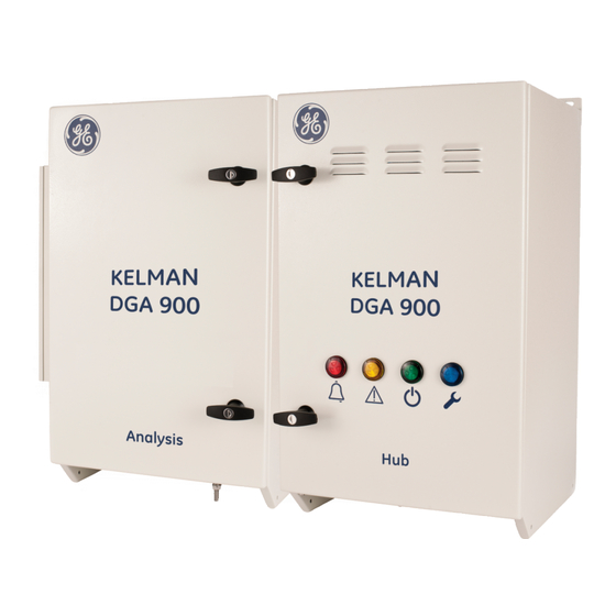
INTRODUCTION Product Overview The Kelman™ DGA 900 (the product) is a multigas online DGA (Dissolved Gas Analysis) and moisture monitoring system for implementing Asset Performance Management (APM) across electrical generation, transmission, distribution and industrial applications. The product as shown in Figure 1-1 can detect and diagnose incipient faults and trend asset health via the monitoring of critical gases including moisture in the transformer oil. - Page 8 Other options may be available on request. ▪ Compatibility with GE’s Perception transformer fleet management software for data download, trending and analysis as well as other SCADA systems. The product is a DS- Agile and Predix-Grid APM ready device with support for industry standard protocols.
-
Page 9: Scope
Scope This guide outlines the use of the HMI, manual sampling function and general maintenance activities. Front Panel LEDs Table 1-1 outlines the LEDs on the front panel of the Hub module. Table 1-1: Hub front panel LED lights LED Colour Symbol Meaning Alarm... -
Page 10: Safety
SAFETY Symbols The meaning of symbols used on the Kelman™ DGA 900: Caution. Refer to the Installation Manual / Operator Guide to prevent death, bodily injury, equipment damage or loss of data. Electrical Hazard. Risk of electric shock. Primary Protective Earth connection. Hot surfaces may be present. -
Page 11: Hazardous Substances
IP56 thresholds depending on the location, pressure and direction of the water jets. Should customers require testing a water deluge system in the area in which the product is installed, GE recommends powering down the product and draping it with a suitable waterproof covering. -
Page 12: Technical Specifications
TECHNICAL SPECIFICATIONS The product meets the following technical specification as outlined in Table 3-1. Table 3-1: Measurements PARAMETER VALUE/MEETS *1 & 10 *2 & 3 GAS MEASURED RANGE ACCURACY REPEATABILITY Hydrogen (H 5 – 5,000 ppm ± 5% or ± LDL <3% Methane (CH 2 –... - Page 13 10 metres or less from oil supply or return valve to product connection point, and on transformer oil supply valve volumes of 200 ml or less. For oil temperatures colder than −20 ºC, GE recommends the use of heat trace cabling on piping. Low oil viscosity reduces oil flow.
-
Page 14: Compliance
COMPLIANCE The product is designed to meet the following type tests as listed in Table 4-1. Table 4-1: Type tests CATEGORY STANDARD CLASS/LEVEL TEST EMC Emissions CISPR 11 Radiated & Conducted Emissions EN 61326- FCC Part 15 Meets the Radiated & Conducted Emissions 1:2006 requirements of A EN 61000-3-2... -
Page 15: Power
POWER The product is wired directly to the mains so is continually powered on. The mains fuse holder for the product is shown in Figure 5-1 and is located towards the bottom right-hand side of the Hub module. Live Neutral Earth Fuse holder Figure 5-1: Fuse holder... -
Page 16: Hmi
Introduction The local HMI features an integrated 7 in. colour LCD panel with resistive touch screen and embedded webserver. The remote HMI is via a wireless comms option (or direct USB connection) to a web browser. The latter being the preferred means of interaction with the product since it offers the convenience of accessing the product from anywhere using a full screen web browser. -
Page 17: Connections
Note: This guide uses screenshots from the remote Web access HMI. The images rendered on the local HMI are similar, but some have a different layout due to the smaller screen. Note: This guide displays screens from an Administrator login. All user logins have a similar look and feel, but some features are dependent on the type of user. -
Page 18: Start-Up Procedure
Start-Up Procedure When the product is powered on or rebooted, the PGA takes several minutes to initialise. If using the remote access HMI, the icon denotes that the initialization process is not yet complete. Login The log-in page prompts for a username and password as shown in Figure 6-3. The product ships with a default username and password that can be changed after initial login. -
Page 19: Dashboard
Figure 6-4: Local HMI: Quick Access page Note: For manual sampling HMI functionality, see Section 7.2. Dashboard After a successful login, the remote HMI displays the Dashboard page in Normal Mode as shown in Figure 6-5. The Dashboard page displays details of the Last DGA measurement, a Quick Access panel, System Information and a trend chart below. - Page 20 Figure 6-5: Dashboard The Last DGA Measurement panel shows the measurement date and time stamp, gas levels (with measurements in PPM) displayed numerically and represented graphically on a bar chart marked with the configured Caution (H for High) and Alarm (HH for High High) levels.
-
Page 21: Quick Access
Click Download Log to access the available log files. Choose from a System Log, TFD Log and CFR Log. These service files contain product performance data that is used to check product functionality. If requested, download and send the relevant log files to the GE M&D Service Support team for analysis. - Page 22 6.5.1.3 Enter Rapid Mode Rapid mode is a means of on demand sampling and uses a smaller quantity of oil to deliver a result in around 30 minutes. Rapid mode measures four critical gases — hydrogen, acetylene, carbon monoxide, carbon dioxide — and water, and charts the measurements below.
-
Page 23: Gas / Diagnostics
GAS / Diagnostics 6.6.1 Active Alarms Select GAS / Diagnostics > Active Alarms to open the Active Alarms page as shown in Figure 6-8. Figure 6-8: Active Alarms Note: Deadbands are specified in the units relating to what is measured. E.g. PPM for gas, degrees Celsius (°C) for temperature. -
Page 24: Duval Triangle
Figure 6-9: Measurements 6.6.3 Duval Triangle Select GAS / Diagnostics > Duval to open the Duval Diagnostic page as shown in Figure 6-10. MA-025 – DGA 900 Operator Guide – Rev 2.0 12-Apr-19 Page 24 of 92... -
Page 25: Gas Ratio
Figure 6-10: Duval Diagnostic 6.6.4 Gas Ratio Select GAS / Diagnostics > Gas Ratio to open the Gas Ratio page as shown in Figure 6-11. Figure 6-11: Gas Ratio MA-025 – DGA 900 Operator Guide – Rev 2.0 12-Apr-19 Page 25 of 92... -
Page 26: Scheduler
6.6.5 Scheduler Select DGA > DGA Scheduler to open the DGA Scheduler page as shown in Figure 6-12. Use this page to schedule a DGA measurement cycle. Figure 6-12: DGA Scheduler Calculations 6.7.1 Gas Ratios Select Calculations > Gas Ratios to open the Gas Ratio Settings page as shown in Figure 6-13. -
Page 27: Relative Saturation
Type a Ratio Name and select the relevant gases. Note: Nitrogen (N ) is available as a choice only if Nitrogen Measurement is enabled. Refer to the IEEE® C57.104 and IEC® 60599 standards for alarm settings or Appendix E. 6.7.2 Relative Saturation Select Calculations >... -
Page 28: Analog Inputs Roc Configuration
6.7.4 Analog Inputs RoC Configuration Select Calculations > Analog Inputs Rate of Change to open the Analog Inputs RoC Configuration page as shown in Figure 6-17. The default is for a CT to be installed on Analogue Input 1. The product supports up to five additional analogue inputs. Figure 6-17: Analog Inputs Rate of Change Configuration MA-025 –... -
Page 29: Alarms
Alarms Perception allows deadbands to be defined for each alarm. A deadband establishes another limit for clearing the alarm and prevents an alarm returning to normal until the alarm condition is cleared by the deadband. This reduces the number of false alarms and the amount of chattering. -
Page 30: Gas Ratios
Click on a gas alarm icon > e.g. Hydrogen to configure the type of alerts as shown in Figure 6-19. Figure 6-19: Hydrogen alerts 6.8.2 Gas Ratios Select Alarms > Gas Ratios to open the Gas Ratio Alarms Configuration page as shown in Figure 6-20. -
Page 31: Gas Rate Of Change
6.8.3 Gas Rate of Change Select Alarms > Gas Rate of Change to open the Gas RoC Configuration page as shown in Figure 6-22. Figure 6-22: Gas RoC Configuration MA-025 – DGA 900 Operator Guide – Rev 2.0 12-Apr-19 Page 31 of 92... -
Page 32: Relative Saturation
6.8.4 Relative Saturation Select Alarms > Relative Saturation to open the Relative Saturation Alarms Configuration page as shown in Figure 6-23. Figure 6-23: Relative Saturation Alarms Configuration Click on a Relative Saturation icon > e.g. High-High to expand the relative saturation definition as shown in Figure 6-24. -
Page 33: Analog Inputs Rate Of Change
6.8.6 Analog Inputs Rate of Change Select Alarms > Analog Inputs Rate of Change to open the Analog Inputs RoC Alarms Configuration page as shown in Figure 6-26. Figure 6-26: Analog Inputs RoC Alarms Configuration 6.8.7 Digital Inputs Select Alarms > Digital Inputs to open the Digital Inputs Alarms Configuration page as shown in Figure 6-27. -
Page 34: Digital Inputs Transition Total
6.8.8 Digital Inputs Transition Total Select Alarms > Digital Inputs Transition Total to open the Digital Inputs Transition Total Alarms Configuration page as shown in Figure 6-28. Figure 6-28: Digital Inputs Transition Total Alarms Configuration MA-025 – DGA 900 Operator Guide – Rev 2.0 12-Apr-19 Page 34 of 92... -
Page 35: Peripherals
Peripherals 6.9.1 Peripheral Scheduler Select Peripherals > Peripheral Scheduler to open the Peripheral Scheduler page as shown in Figure 6-29. Figure 6-29: Peripheral Scheduler The Peripheral Scheduler allows the Measurement Time Interval to be set to 5, 10, 15 or 20 minutes. -
Page 36: Digital Inputs
Figure 6-31: Analog Input 4 (4-20 mA Temperature Sensor) 6.9.3 Digital Inputs Select Peripherals > Digital Inputs to open the Digital Input Configuration page as shown in Figure 6-32. Figure 6-32: Digital Input Configuration 6.9.4 Input Measurements Select Peripherals > Input Measurements to open the Input Measurements page as shown in Figure 6-33. -
Page 37: Settings
6.10 Settings 6.10.1 Communications Select Settings > Communications to open the Communications Settings page as shown in Figure 6-34. Figure 6-34: Communications Settings If a GPRS modem is fitted and the appropriate carrier sim is installed, the IP address also displays. -
Page 38: Date & Time
6.10.2 Date & Time Select Settings > Date & Time to open the Date & Time page as shown in Figure 6-35. Figure 6-35: Date & Time 6.10.3 SMS Alerting Select Settings > SMS Alerting to open the SMS Alerting page as shown in Figure 6-36. In this example, the system is configured to send ‘Richard’... -
Page 39: Firewall
6.10.4 Firewall To create a custom security policy, select Settings > Firewall to open the Firewall Settings page as shown in Figure 6-37. Rules can be added, edited or deleted to create a suitable access policy for each type of interface. These rules are used to block unused ports and specify distinct firewall actions (accept, reject or drop) based on the IP address or port. -
Page 40: Communication Services
Select the relevant slider button to enable/disable the relevant communication service. E.g. Modbus-TCP, SSH (Secure Shell) and HTTPS — but do not rely on the firewall settings. To implement a custom security policy, upload a new certificate to replace the GE self- signed certificate and enable HTTPS requests only. -
Page 41: Service
6.11 Service 6.11.1 Measurement Select Service > Measurement to open the Measurement Settings page as shown in Figure 6-39. The Normalization Temperature is a thermostatically controlled internal target temperature for the Analysis module. Depending on the region, one of two temperatures can be set 0 °C or 20 °C. -
Page 42: Controller Reprogramming
6.11.2 Controller Reprogramming Consult with Technical Support to confirm the availability of new firmware for the Controller PCB. Upgrade to the latest version of the firmware via an Ethernet connection to avail of new features. Note: A firmware upgrade resets passwords back to their default values. To upgrade the Controller PCB firmware, select Service >... -
Page 43: I/O Pcb Reprogramming
6.11.3 I/O PCB Reprogramming Consult with Technical Support to confirm the availability of new firmware for the I/O PCB. Upgrade to the latest version of the firmware via an Ethernet connection to avail of new features. Note: A firmware upgrade resets passwords back to their default values. To upgrade the I/O PCB firmware using an Ethernet connection, select Service >... -
Page 44: Oxygen Sensor
6.11.4 Oxygen Sensor Select Service > Oxygen Sensor to open the Oxygen Sensor settings page as shown in Figure 6-44. Figure 6-44: Oxygen Sensor MA-025 – DGA 900 Operator Guide – Rev 2.0 12-Apr-19 Page 44 of 92... -
Page 45: Gas Normalization
6.11.5 Gas Normalization Select Service > Gas Normalization to open the Gas Normalization Settings page as shown in Figure 6-45. Figure 6-45: Gas Normalization Settings 6.11.6 Factory Select Service > Factory to open the Factory Settings page as shown in Figure 6-46. Figure 6-46: Factory Settings MA-025 –... - Page 46 6.11.6.1 Alarm Reflash The Alarm Reflash option ensures that a relay’s digital output reflashes (if already activated) when another source triggers the same relay. An alarm reflash applies only to relays 1-6 and is achieved by deactivating the relevant digital output for a duration of 1 second before reactivating it to achieve a flashing effect.
- Page 47 6.11.6.4 Factory Reset Clears everything — historical measurement data, configuration settings and communication settings, so that the product returns to the initial factory state. Table 6-2 outlines the type of data items that get erased. Table 6-2: Factory Settings: Data and configuration cleardown Clear Reset of Full Factory...
-
Page 48: User Administration
Figure 6-47: Simulation mode This allows the HMI to display realistic sample data for showcasing e.g. training and testing purposes without affecting real-time data, but has no validity since it does not relate to any underlying measurement cycles. 6.11.6.6 Restart Device Some configuration changes require a device restart. - Page 49 Figure 6-50: Change Password A password strength is categorised as listed in Table 6-3. Table 6-3: Password Strength Password Strength Rating Description Not enough No password entered. Weak 4 characters or more. Medium 7 characters or more. The string must contain at least one each of the following characters: lowercase alphabetical, uppercase alphabetical and numeric.
-
Page 50: Transopto
6.12 TransOpto 6.12.1 Measurements Select TransOpto > Measurements to open the TransOpto Measurements page as shown in Figure 6-51. Figure 6-51: TransOpto Measurements 6.12.2 Rate of Change Select TransOpto > Rate of Change to open the TransOpto RoC Configuration page as shown in Figure 6-52. -
Page 51: Alarms
6.12.3 Alarms Select TransOpto > Alarms to open the TransOpto Alarms Configuration page as shown in Figure 6-53. Figure 6-53: TransOpto Alarms Configuration Click on a channel alarm icon > e.g. ‘Channel 1 High’ to configure the type of alerts as shown in Figure 6-54. -
Page 52: Rate Of Change Alarms
6.12.4 Rate of Change Alarms Select TransOpto > Rate of Change Alarms to open the TransOpto RoC Alarms Configuration page as shown in Figure 6-55. Figure 6-55: TransOpto RoC Alarms Configuration Click on a channel alarm icon > e.g. ‘Channel 2 High-High’ to configure the type of alerts as shown in Figure 6-56. -
Page 53: Channels
6.12.5 Channels Select TransOpto > Channels to open the TransOpto Channels Settings page as shown in Figure 6-57. Figure 6-57: TransOpto Channels Settings 6.12.6 Settings Select TransOpto > Settings to open the TransOpto Settings page as shown in Figure 6-58. Figure 6-58: TransOpto Settings MA-025 –... -
Page 54: Logout
6.13 Logout Select the Logout option below the username as shown in Figure 6-59. Figure 6-59: Logout The Log-in page displays as shown in Figure 6-60. Figure 6-60: Log-in page MA-025 – DGA 900 Operator Guide – Rev 2.0 12-Apr-19 Page 54 of 92... -
Page 55: Shutdown Procedure
6.14 Shutdown Procedure If the product is to be shut down, perform the following steps: Log in to the DGA 900 to observe the operating state on the dashboard as shown in Figure 6-61. Figure 6-61: System Info – Standby If the product is in “Standby”... -
Page 56: Error Notifications
6.15 Error Notifications The Measurements page reports all errors as shown in Figure 6-63: If there are no errors in the current measurement cycle, the results are displayed as normal. Errors for the most recent measurement cycle are listed first. Use the navigation buttons to move through the various measurement cycles and examine any errors encountered in previous measurement cycles. - Page 57 Figure 6-64: PGA Errors Note: If the Oxygen sensor is not enabled, no Oxygen sensor state or error codes display. MA-025 – DGA 900 Operator Guide – Rev 2.0 12-Apr-19 Page 57 of 92...
-
Page 58: Error Codes
6.15.1 Error Codes Table 6-4 lists the PGA error codes. All the service alarm error codes are accompanied by illumination of the blue Service light that is visible on the front door of the product. Note: Error codes are offset by 1 from the Modbus register bit numbers. Note: This information relates to PGA firmware version 18.1.5 for DGA 900. -
Page 59: Other Notifications
Table 6-5 lists the Oxygen sensor error codes. Table 6-5: Oxygen sensor error codes Code Error Note Oxygen sensor measurement has finished with no error. System error. Internal state. Initial state of state machine. System error. Internal error. Oxygen sensor thread is busy. Oxygen sensor is disabled. -
Page 60: Manual Oil Sampling
Figure 7-1: Oil filter and oil ports (front view of Analysis module) A male quick-connect fitting and valve assembly is provided in the product installation kit. GE also recommends the use of a 50-mL ground glass syringe. Note: The manual oil sampling arrangement and the quick-connect sampling port must not be cleaned with any type of solvent as this could affect results for subsequent oil samples. -
Page 61: Local Hmi For Manual Sampling
OPEN Figure 7-3: Sampling assembly Quick-connect body protector CLOSED with pull-down collar for release Oil sampling valve assembly with Luer fitting Figure 7-4: Luer fitting on assembly Figure 7-2: Valve orientation Local HMI for manual sampling The manual sampling functionality is implemented on the Quick Access page of the local HMI only as shown in Figure 7-5. - Page 62 The Manual Sampling page displays. Press Start as shown in Figure 7-6 to start the manual sampling process. Figure 7-6: Manual Sampling The oil purging process starts. Allow several minutes for the oil to purge and then press Continue when done. Figure 7-7: Purging Oil MA-025 –...
- Page 63 The system prompts the user to take the manual oil sample. See Section 7.3 for more details on the sampling process. Press Finish to return to the home page as shown in Figure 7-8. Figure 7-8: Take manual oil sample If the product is already performing a measurement, manual sampling is prevented as shown in Figure 7-9.
- Page 64 Either wait for the current measurement cycle to finish or stop the current measurement cycle. To stop the current measurement cycle, return to the Dashboard and press Stop Measurement as shown in Figure 7-10. Figure 7-10: Dashboard: Stop Measurement The product is now ready to take a manual sample. MA-025 –...
-
Page 65: Sampling Process
Sampling Process Logon to the product using the local HMI and observe the product state on the Dashboard. The product state must be in Standby to initiate manual sampling. Figure 7-11 and the accompanying steps detail the process to obtain a manual oil sample. Standby state Measurement state Press Stop... - Page 66 Observe the product state on the HMI Dashboard page. Either wait for the product to return to the Standby state or use the HMI to stop the current measurement cycle. If the product is in “Standby” state, proceed to step 3. If the product is in a measurement state, manual sampling is prevented.
-
Page 67: Communications
Password: perception Refer to the Perception software documentation (v 1.22.3 or later) for further details. TECHNICAL SUPPORT For technical support, please contact the GE Customer Service Centre (24 hours a day, 365 days a year): T +44 1785-250-070 (United Kingdom) -
Page 68: Appendix A Security Configuration
Use whitelisting software on control systems PCs and keep the whitelist up to date. A.1.2 Sample Checklist This section provides a sample checklist to help guide the process of securely deploying GE products. ▪ Create or locate a network diagram. - Page 69 ▪ On each GE product, change every supported password to something other than its default value. ▪ Harden the configuration of each GE product, disabling unneeded features, protocols and ports. ▪ Test / qualify the system. ▪ Create an update/maintenance plan.
- Page 70 Select the relevant slider button to enable/disable the relevant communication service. E.g. Modbus-TCP, SSH (Secure Shell) and HTTPS — do not rely on the firewall settings. To implement a custom security policy, upload a new certificate to replace the GE self- signed certificate and enable HTTPS requests only.
- Page 71 Use the HMI to login as either ‘Administrator’ or ‘Operator’. ▪ Select Settings > Communication Services. ▪ To implement a custom security policy, upload a new certificate to replace the GE self- signed certificate and enable HTTPS requests only. MA-025 – DGA 900 Operator Guide – Rev 2.0 12-Apr-19...
- Page 72 The DGA 900 has a built-in firewall that defines the security settings for the various interfaces. Firewall policies are configured separately for each interface (Ethernet, USB, GSM-GPRS modem). The DGA 900 ships with a standard GE self-signed certificate with the firewall enabled by default to accept all HTTP requests. You should customise the firewall.
- Page 73 Figure A-4: Default policy options A.4.2 Specific Policies The specific policy adds exceptions to the default policy. Click the ‘Create new rule’ button to create a new policy. The rule options are as shown in Figure A-5. Figure A-5: Specific policy options A.4.3 Disable all Connections on a dedicated interface In the Firewall Settings page, select the interface type e.g.
- Page 74 Figure A-8: Accept HTTPS In the ‘Rule Name’ field, type a descriptive name e.g. Accept HTTPS. In the ‘IP’ field, select the IP checkbox and specify/edit the IP address e.g. 192.168.0.124. In the ‘Port’ field, select the Port checkbox and type 443. In the ‘Firewall Action’...
-
Page 75: Appendix B Transportation Pga Lock
Appendix B Transportation PGA Lock The Analysis module is equipped with a factory-fitted transportation PGA lock that consists of a metal locking bracket, two metal securing pins, two plastic nuts and three cable ties as shown in Figure B-1. Figure B-1: PGA lock – engaged The lock is engaged prior to shipping, but must be disengaged prior to operation of the product. - Page 76 The transportation PGA lock is now disengaged rendering the PGA anti-vibration mounts active. If the product is transported and reconnected to a different substation asset, it must be recommissioned by a GE-approved commissioning engineer. MA-025 – DGA 900 Operator Guide – Rev 2.0...
- Page 77 Fit the lock To fit the PGA lock, reverse the procedure outlined in Appendix B.1: ▪ Insert the metal bracket into the vibration mount assembly as shown in Figure B-6. Figure B-6: PGA lock – insert metal bracket ▪ Secure the metal bracket to the anti-vibration mounts using the two plastic nuts as shown in Figure B-9.
- Page 78 ▪ Ensure that each pin end is fully inserted into the hole in the back wall of the enclosure as shown in Figure B-9. Figure B-9: PGA lock – pin to enclosure hole ▪ Use three cable ties to secure the pins to the metal bracket at the appropriate holes as shown in Figure B-10.
-
Page 79: Appendix C Maintenance Activities
Figure C-2: Marshalling PCB coin cell battery The following steps describe how to change the battery: 1. Back up the product data — contact your GE representative. 2. Power off the relevant module. 3. Open the door on the relevant module to locate the battery on the relevant board. - Page 80 Air Filter Replacement The Hub module draws air from the base and expels it via the air outlet on the front door. The intake air is filtered to remove the largest particles, so depending on environmental conditions, the air filter cartridge may need periodic replacement. To replace the air intake filter: First isolate the product through the external circuit breaker or external switch and apply LOTO.
- Page 81 First isolate the product through the external circuit breaker or external switch and apply LOTO before opening the door. Remove the eight M5 aerotight nuts that secure the Louvre catchment tray to the top rear of the front door as shown in Figure C-7, and then lift the tray away from the neoprene 3 mm gasket as shown in Figure C-8.
- Page 82 Figure C-11: Oil connections Figure C-12 shows the oil filter location with the filter element removed. Figure C-12: Oil filter Before removing the filter housing, first isolate the product through the external switch or circuit breaker and ensure that the oil supply valve is closed.
- Page 83 Remove the stainless steel filter element and clean it using a brush and compressed air (or replace with a new filter, order FITT01029H). Then replace the filter back into its housing and re-secure the oil filter cover using the four M3 hex bolts. Replace the black insulating push-fit cover by inserting the bottom end first.
- Page 84 Power on the product. Hood Hex bolts (six highlighted) Electrical clip connector Figure C-14: Peltier cooler Figure C-15: Fan group electrical connection Cooling fins Detached fan group Figure C-16: Peltier cooling fins Figure C-17: Fan group detached from cooler MA-025 – DGA 900 Operator Guide – Rev 2.0 12-Apr-19 Page 84 of 92...
-
Page 85: Appendix D Time Sync Implementation
Appendix D Time Sync Implementation The product has a time-sync feature that allows users to synchronize the clock. This Appendix explains the data format options for the “time sync” and its implementation. Time Format Under the standard Modbus® register list, the timing is defined in Table D-1. Table D-1: Timing Group Register... - Page 86 When testing, please check that you are reading registers 1197-1198 (assuming addresses start at 999 +1) and decoding an unsigned 32-bit big endian number. The epoch time is in UTC. This matches the device time. An online converter e.g. http://www.epochconverter.com/ can be used to verify.
-
Page 87: Appendix E Alarm Settings: General Advice
Appendix E Alarm Settings: General Advice Note: This Appendix is based on Technical Bulletin No 18 (amended below for DGA 900). Introduction There are published standards for interpretation of DGA results. The main internationally recognised standards are IEEE® C57.104 and IEC® 60599. It is recommended that the customer refers to these or local standards for more information on DGA interpretation. - Page 88 Table E-1: Main Tank: Gas Level Alarms µL/L or Hydrogen Methane Acetylene Ethylene Ethane Carbon Carbon TDCG (H2) (CH4) (C2H2) (C2H4) (C2H6) monoxide dioxide (CO) (CO2) IEEE STD 2500 Condition 1 1) Set alarms to the following only if the measurements taken are LESS THAN the above values. (C2H2 is set slightly higher to avoid spurious alarms) Caution 2 or 4*...
- Page 89 transformer (4,000 l oil), the same 1 ppm/day gas increase means a ROC of 4 ml/day. In either case there is a defect, but in the larger transformer the defect is much more severe. E.4.1 Using Oil Volume It is strongly recommended to use ROC in ml/day. Convert the ppm/day figure to ml/day based on the oil volume or weight: ...
- Page 90 Table E-3: ROC alarms (for ROC in ml/day) ml/day Hydrogen Methane Acetylene Ethylene Ethane Carbon Carbon TDCG monoxide dioxide (CO) Caution 0.05 Alarm Measurement Intervals If the customer does not have a policy for measurement intervals, use the following measurement intervals (in hours): Table E-4: Measurement intervals In Hours DGA 900...
- Page 91 E.8.1 Caution There may be cases where the transformer suddenly fails (between measurements at the normal measurement interval). The customer should be made aware that online monitoring equipment is not capable of detecting such rapid (often catastrophic) failures. DGA monitoring is designed for the detection of incipient slow-developing faults. Other protective devices (Buchholz relay, pressure relief device, over-current and differential current protection, etc…) should be used in conjunction with DGA monitoring equipment to provide complete protection for the transformer.
-
Page 92: Contact & Copyright Details
Other company or product names mentioned in this document may be trademarks or registered trademarks of their respective companies. GE reserves the right to make changes to specifications of products described at any time without notice and without obligation to notify any person of such changes.