
Related Manuals for ABB Three Phase Mechanical AutoLink


Summary of Contents for ABB Three Phase Mechanical AutoLink
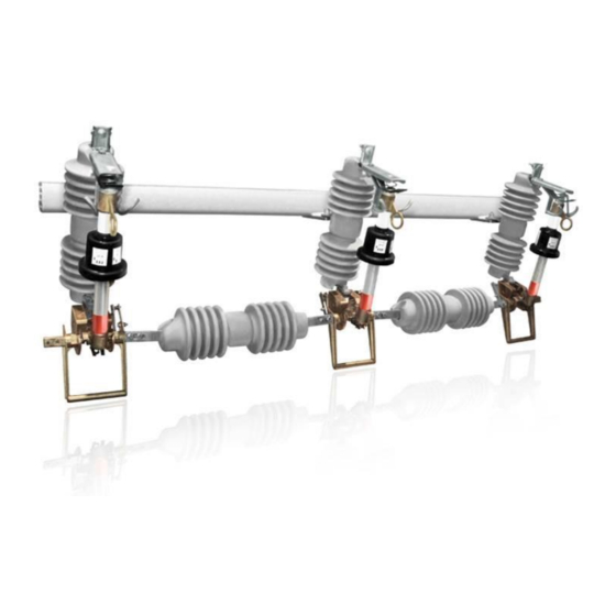
- Page 1 1YSA160003-EN - Rev. 5 Instruction Manual Three Phase Mechanical AutoLink Three Phase Mechanical Electronic Sectionalizer 15kV / 27kV 125kV / 150kV ...
-
Page 2: Table Of Contents
1YSA160003-EN - Rev. 5 2 / 19 Table of Contents Section A: Safety Notices ......................3 Section B: Introduction ......................4 B.1. About this Document ........................... 4 B.2. Target Group ............................4 B.3. Related Documentation ........................4 Section C: Operation of the AutoLink ..................5 C.1. -
Page 3: Section A: Safety Notices
ABB investigate such ways. Anyone using service procedures or tools, whether or not recommended by ABB, must satisfy himself thoroughly that neither personal safety nor equipment safety will be jeopardized by the service method or tools selected. -
Page 4: Section B: Introduction
Section B: Introduction B.1. About this Document This document contains the required information to install medium voltage Three Phase Mechanical AutoLink and put it into service. For a correct use of the product, please read it carefully. Like every apparatus we manufacture, Three Phase Mechanical AutoLink is designed for specific applications. -
Page 5: Section C: Operation Of The Autolink
1YSA160003-EN - Rev. 5 5 / 19 Section C: Operation of the AutoLink C.1. General The AutoLink Electronic Sectionalizer is a protection device that operates at a permanent fault in the distribution line. It must be used together with an upstream recloser or circuit breaker with reclosure capability. Please take note that the AutoLink is not a fuse tripping device, therefore it cannot be used as a protection device by itself. -
Page 6: Operating Under Permanent Fault Conditions
1YSA160003-EN - Rev. 5 6 / 19 Figure 2. C.2.2. Operating Under Permanent Fault Conditions The remaining 10-20% of faults in distribution overhead lines are considered permanent. During these faults, the continuous cycling of the recloser does not clear the fault. .The AutoLink will pickup, measure zero current and count, reaching its trip count setting. The AutoLink will trip on the last open cycle of the recloser, isolating the permanent fault in its branch and allowing the recloser to close prior to going to lockout and maintain power to the unaffected branches. -
Page 7: Minimum Autoreclosing Operating Time Required For Autolink Operation
1YSA160003-EN - Rev. 5 7 / 19 Minimum Current - Time Requirement Current [A] Figure 4. C.4. Minimum Autoreclosing Operating Time required for AutoLink operation The AutoLink requires a line current greater than 5 A in order to be fully charged during at least 15 seconds. After the condition of the device is fully charged the line current can vary as low as 3A and it will continue to be operative. -
Page 8: Section D: Preparing For Use
Make sure that all materials described in the shipping note are included in the supply. If any damage or irregularity is seen in the supplied product after unboxing, notify ABB (directly or through the agent or distributor) as soon as possible within five days of receipt. Please inquire about the terms of warranty from your nearest ABB representative. -
Page 9: Installation
ANSI C37 63: Automatic Sectionalizer. All accident prevention regulations in relative countries. The AutoLink is compatible with the Fuses bases model ICX from ABB, Type XS from SYC, Type C from AB Chance and Type L from Cooper. For special installation requirements or other operating conditions, please contact ABB. -
Page 10: Opening Of The Unit
1YSA160003-EN - Rev. 5 10 / 19 D.4.3.2. Opening of the Unit Remove the top cap (See Figure 1-A) using a 34mm fork spanner holding the tube with the hand (See Figure 1-B). Check condition of O-ring (See Figure 2-E), and replace it if necessary, applying grease on it. Figure 7. -
Page 11: Closing Of The Unit
1YSA160003-EN - Rev. 5 11 / 19 Table 1 and 2. D.4.3.4. Closing of the Unit Once the calibration current and counts are set, cover the dip-switch with silicon grease (See Figure 3), supplied with AutoLink. Figure 9. Check the condition of the O-Ring (See Figure 2-E) and apply silicon grease (See Figure 4-F) both inside the cap and over the dip- switches. -
Page 12: Autolink Repositioning
1YSA160003-EN - Rev. 5 12 / 19 Figure 10. Place the cap, holding the tube with the hand, and tighten it using a 34 mm fork spanner (torque between 8 and 10 Nm) without damaging the O-Ring (See Figure 5). Figure 11. - Page 13 1YSA160003-EN - Rev. 5 13 / 19 Figure 12. Turn the tensioning device support (See Figure 7). Place the tensioning device support facing the interlocking bolt. Figure 13. Turn the tripping pin 90°, until the lower contact is firmly blocked (See Figure 8).
-
Page 14: Lifting The Device
14 / 19 Figure 14. D.4.3.6. Lifting the Device The Three Phase Mechanical AutoLink is raised by means of two eyebolts placed in the sides of the galvanized cross mounting bracket. D.4.3.7. Pole fixture The Three Phase Mechanical AutoLink is fixed to the pole by means of the following brackets (See Figure 9). - Page 15 1YSA160003-EN - Rev. 5 15 / 19 Figure 16.
-
Page 16: Mounting The Autolinks In The Three Phase Body
1YSA160003-EN - Rev. 5 16 / 19 D.4.3.8. Mounting the AutoLinks in the three phase body For each AutoLink place the hookstick in the tube’s lower contact eyelet and mount in the isolating support body. Figure 17. Withdraw the pole and place it in the tube’s superior eyelet (See Figure 10). Push it until it remains in closing position. Figure 18. -
Page 17: Commissioning
1YSA160003-EN - Rev. 5 17 / 19 D.5. Commissioning D.5.1. General procedures When commissioning, all operations must be carried out by suitable qualified customer personnel with in-depth knowledge of the apparatus and the installation itself. It is not recommended to open AutoLink under charge using a common hookstick, as it could cause an arc that might damage the personnel or the equipment. -
Page 18: Section E: Maintenance
- Check the upper contact cap is correctly fastened and both the o-ring and the silicon grease are present. Test should be carried out on a laboratory with the appropriate equipment to simulate service conditions. For this operation it is recommended to contact ABB to request the testing procedure. - Page 19 Valentin Alsina (B1822CJU) Buenos Aires. Argentina. Telephone: +54 11 4229 5500 www.abb.com.ar ©Copyright 2015 ABB, All rights reserved Document Title: Three Phase Mechanical AutoLink User Manual Document No. Date & Rev. Ind. No. of Pages Page 1YSA160003-EN Feb 2015 - Rev 5...