Bosch DICENTIS Hardware Installation Manual
Hide thumbs
Also See for DICENTIS:
- Configuration manual (134 pages) ,
- Software manual (99 pages) ,
- Installation manual (61 pages)
Table of Contents
Advertisement
Advertisement
Table of Contents

Related Manuals for Bosch DICENTIS


Summary of Contents for Bosch DICENTIS
- Page 1 DICENTIS Conference System Hardware Installation Manual...
-
Page 3: Table Of Contents
Using a cable coupler to insert power locally 5.1.5 Using a cable coupler to switch the system on DICENTIS System Cable Assemblies DCNM-CBCON Connectors for DICENTIS cable DCNM-CBTK System Network Cable Toolkit DCNM-CB250-I System Installation Cable DCNM-IDESKINT On-air & teleph. DCNM-IDESK... -
Page 4: Safety
These instructions are supplied together with all equipment that can be connected to the mains supply. Safety precautions Some of the DICENTIS Conference System products are designed to be connected to the public mains network. To avoid any risk of electric shock, all interventions must be carried out with disconnected mains supply. - Page 5 Note: The FCC and IC Wireless statement applies to: – DCNM-MMD2 – DCNM-D – DCNM-DVT – DCNM-DSL – DCNM-DE – DCNM-IDESK – DCNM-IDESKVID Bosch Security Systems B.V. 2021.01 | V2.2 | Hardware Installation Manual...
-
Page 6: About This Manual
| About this manual DICENTIS About this manual The purpose of this manual is to provide information required for installing the DICENTIS Conference System. This installation manual is available as a digital document in the Adobe portable document format (PDF). - Page 7 V1.6 edition. Sections updated: 5.5.3, 5.5.4. 2018.04 V1.7 edition. Sections updated: 3.1, 3.2, 4.3.1, 4.3.2, 4.4, 5.2, 5.4, 5.5.4. New section: 7.2 DCNM- IDESK and DCNM-IDESKVID Interpreter desk added. Bosch Security Systems B.V. 2021.01 | V2.2 | Hardware Installation Manual...
- Page 8 2019.12 V2.0 edition. Sections updated: 3.2 System extension, 4.3.1 Calculation using DCNM-APS(2) or DCNM-PS(2), 6.3 Dante gateway. New sections: 7.2 DICENTIS Flush mounted devices, 7.2.1 DCNM-FSL Flush language selector. 2020.05 V2.1 edition. Sections updated: 3 System installation overview, 7.1 DICENTIS tabletop devices, 7.2 DICENTIS flush-mounted...
-
Page 9: System Installation Overview
It is advisable to participate in the DICENTIS Conference System training before you install, configure, prepare, and operate a DICENTIS Conference System. The DICENTIS Conference System is an IP based conference system which runs on an OMNEO compatible Ethernet network. It is used for distributing and processing audio, video and data signals. -
Page 10: Typical System Setup
CAT‑5e Ethernet cable (minimum requirement). Powering switch (DCNM-PS2): – Is used to increase the number of DICENTIS devices connected to the system. Audio processor and powering switch (DCNM-APS2): – Controls the system audio, routes audio from and to the system and supplies power to the DICENTIS devices. - Page 11 This device is used via a “Power over Ethernet” (PoE) Ethernet switch. Note: Only one DICENTIS device should be connected here. Participants can use their DICENTIS Discussion device to contribute to a meeting: DCNM-D, DCNM-DVT, DCNM-DSL, DCNM-DE. A typical camera setup in a DICENTIS Conference System consists of: Figure 3.2: Typical camera setup...
- Page 12 _____ DCNM-Cables This system overview does not give information on redundant network options. For more information, refer to Redundancy options, page 28 . Refer to – Redundancy options, page 28 2021.01 | V2.2 | Bosch Security Systems B.V. Hardware Installation Manual...
-
Page 13: System Extension
The DICENTIS Conference System is scalable from small to medium to large. This section describes what a small, medium and large system is and what the requirements are for these systems: A small to medium DICENTIS Conference System (see Typical system setup, page 10 ) consists – up to 450 DICENTIS nodes. - Page 14 If more than one subnet is required, two types of an ARNI must be used. – OMN-ARNIS (ARNI‑S OMNEO interface): The ARNI‑S is required for increasing the system size above 450 DICENTIS nodes. It supports up to 450 DICENTIS nodes in its subnet. It also acts as a DHCP server in its subnet. –...
- Page 15 DICENTIS System installation overview | en Maximum number of DICENTIS devices in a string: – The max age timer should be set to 22 when RSTP is used for cable redundancy to prevent a defective cable or powering switch from influencing the system.
- Page 16 | System installation overview DICENTIS Multi subnet DICENTIS Conference System The following figure illustrates a typical multi subnet DICENTIS Conference System with a total of 750 DICENTIS devices. – The system is divided over four (4) subnets, where two (2) subnets having a maximum of 450 DICENTIS nodes and an OMN-ARNIS are connected.
-
Page 17: System Installation Design And Planning
Notice! Make sure that the cable lengths and power consumptions do not exceed the specifications. Not doing so will result in malfunctioning at any moment of the DICENTIS Conference System and products. System capabilities The capability of the DICENTIS Conference System and DICENTIS products depends on: –... - Page 18 The calculation tool is on the DVD supplied with the Audio processor and powering switch and is part of the DICENTIS software DCNM.iso file. The DCNM.iso file can be downloaded from the Bosch website at: https://licensing.boschsecurity.com/software...
-
Page 19: Hardware Requirements
Warning: Please check thoroughly if your switch’s highest priority queue is label as #1 or e.g. #8, because this may differ per brand. Unfortunately this is not consistent over the different brands. Setting it wrong is worse than not having priority. Bosch Security Systems B.V. 2021.01 | V2.2 | Hardware Installation Manual... - Page 20 Forwarding_delay = 30 seconds – Max_age = 22 seconds Diagnostics Link Layer discovery IEEE 802.1AB For network diagnoses using Network Docent. SNMP SNMP For network diagnoses using Network Docent. 2021.01 | V2.2 | Bosch Security Systems B.V. Hardware Installation Manual...
- Page 21 – Non-blocking backplane per switching port, i.e. 2 Gbit per port (e.g. 16 Gbps for an 8‑port router). – MAC address table of at least 1000 addresses per directly connected subnet. Bosch Security Systems B.V. 2021.01 | V2.2 | Hardware Installation Manual...
-
Page 22: Power Supply Capacity Calculation Plan
It is advisable to use the power calculation tool. The calculation tool is on the DVD supplied with the Audio processor and powering switch and is also part of the DICENTIS software DCNM.iso file, which can be downloaded from the Bosch website at: https:// licensing.boschsecurity.com/software... - Page 23 PoE switches, page 25 for more information. Ordering number Cable lengths DCNM-CB02-I 6.56 DCNM-CB05-I 16.40 DCNM-CB10-I 32.81 DCNM-CB25-I 82.02 Tab. 4.4: Cable types and lengths Rear view Figure 4.2: Audio processor and powering switch Bosch Security Systems B.V. 2021.01 | V2.2 | Hardware Installation Manual...
- Page 24 Max. power output (W) Max. devices Socket 1 (12) No power capacity Socket 2 (13) Socket 3 (15) Socket 4 (17) Socket 5 (19) Tab. 4.5: Power supply capacity DCNM‑APS2 / DCNM‑PS2 2021.01 | V2.2 | Bosch Security Systems B.V. Hardware Installation Manual...
-
Page 25: Calculation Using Poe Switches
Calculation using PoE switches, page 25 4.3.2 Calculation using PoE switches Select one or more PoE Ethernet switches to supply power to the DICENTIS devices. Each DICENTIS device must be connected to an individual PoE enabled output of an Ethernet switch. - Page 26 | System installation design and planning DICENTIS Figure 4.4: Bottom view DICENTIS devices (DCNM-MMD / DCNM-MMD2) Figure 4.5: Bottom view DICENTIS devices (DCNM-D / DCNM-DVT / DCNM-DSL / DCNM-DE) Figure 4.6: Bottom view DICENTIS Interpreter devices (DCNM-IDESK / DCNM-IDESKVID) Item Description Network connector 2021.01 | V2.2 |...
- Page 27 DICENTIS System installation design and planning | en Item Description Network / PoE connector Bosch Security Systems B.V. 2021.01 | V2.2 | Hardware Installation Manual...
-
Page 28: Redundancy Options
| System installation design and planning DICENTIS Redundancy options DICENTIS Conference Systems can be created with network redundancy. This ensures that the system will continue to work if: – a network cable is defective or accidentally disconnected. – one of the components fails. -
Page 29: Redundant Cabling For Dcnm-Aps2/Dcnm-Ps2 Units
The # sign shows the way the devices are counted. In the example below up to 19 (22 - 3 = 19) discussion devices can be connected. Figure 4.7: DICENTIS discussion devices connected with redundant cabling between DCNM-PS2 / DCNM-APS2 type units... - Page 30 DCNM-PS2 units. Notice! Rapid Spanning Tree Protocol (RSTP) must be enabled in the DICENTIS Conference System for these redundancy options to work correctly. Refer to –...
-
Page 31: Redundant Server Pc
3 DCNM-APS2 4 DCNM-PS2 5 DICENTIS cabling (redundant loop) For this option to work the DICENTIS Conference System has to be run in combination with EverRun Enterprise software from Stratus Technologies. For more information, refer to the Stratus Technologies website. -
Page 32: Installation Material And Tools
– to extend cables, – in a floor pod as break-out box, – as an interface between DICENTIS cable and “standard” CAT-5E cable combined with a separate power cable, – to insert power locally to the participant devices, – to switch the system on by using two cable couplers and a switch. -
Page 33: Using A Cable Coupler To Extend A Cable
Using a cable coupler as a break-out box The DICENTIS Cable coupler can be used in a floor pod as a break-out box, for example, if you want to connect temporary devices like a rostrum microphone. The cable coupler can be fixated using the screw holes (2.5 mm) or via a tie wrap through the recessed area. -
Page 34: Using A Cable Coupler As An Interface Between Different Types Of Cable
Using a cable coupler as an interface between different types of cable The cable coupler can be used as an interface between DICENTIS cable and “standard” CAT-5E cable, optionally combined with a separate power cable. This can be used, for example, when standard CAT-5E cabling coming from the technical room has to be connected with DICENTIS cable in the conference room. -
Page 35: Using A Cable Coupler To Insert Power Locally
Risk of electric shock. Exposed power cables are a potential hazard. Make sure all power cables are securely fastened by fixing them with a tie wrap on the inside of the box (see drawing ‘Creating a tension relief’). Bosch Security Systems B.V. 2021.01 | V2.2 | Hardware Installation Manual... -
Page 36: Using A Cable Coupler To Switch The System On
– the ripple should be less than 200 mV pk-pk – maximum output current should not exceed 3.0 A (or limited to 3.0 A, because DICENTIS cables and devices have a maximum rating for this current) – Advice – It is strongly advised that the power supply has its own short circuit protection with a short circuit output current ranging from 4.3 to 5.0 A. - Page 37 Figure 5.7: Creating a tension relief, tie wrap prevents the power cables from being pulled out accidentally. Note: – The cable length is not allowed to exceed 100 m. – No more than 2 cable couplers can be used in one trunk. Bosch Security Systems B.V. 2021.01 | V2.2 | Hardware Installation Manual...
-
Page 38: Dicentis System Cable Assemblies
DICENTIS System Cable Assemblies The DICENTIS System Cable Assemblies, terminated with connectors on both ends, are available in different lengths and are used to connect DICENTIS devices to each other. The cable consists of a low smoke zero halogen solid core. - Page 39 DICENTIS Installation material and tools | en Ordering number Cable lengths DCNM-CB05-I 16.40 DCNM-CB10-I 32.81 DCNM-CB25-I 82.02 Tab. 5.6: Cable types and lengths Figure 5.9: DCNM-CBxx-I cable and connector view Bosch Security Systems B.V. 2021.01 | V2.2 | Hardware Installation Manual...
-
Page 40: Dcnm-Cbcon Connectors For Dicentis Cable
Power contact cavity (2 places) Housing Locking latch Signal contact cavity (8 Places) Refer to – DICENTIS System Cable Assemblies, page 38 – DCNM-CB250-I System Installation Cable, page 42 – DCNM-CBTK System Network Cable Toolkit, page 41 2021.01 | V2.2 | Bosch Security Systems B.V. -
Page 41: Dcnm-Cbtk System Network Cable Toolkit
Installation material and tools | en DCNM-CBTK System Network Cable Toolkit The system network cable toolkit is used to connect the DCNM-CBCON Connectors for DICENTIS cable, page 40 to the DCNM-CB250-I System Installation Cable, page 42 or DICENTIS System Cable Assemblies, page 38 . Item Description Power wiring tool. -
Page 42: Dcnm-Cb250-I System Installation Cable
The system installation cable, without connectors, is available in a length of 250 meters and is used for making your own system network cable. Refer also to the sections DCNM-CBCON Connectors for DICENTIS cable, page 40 and DCNM-CBTK System Network Cable Toolkit, page 41 . -
Page 43: Dcnm-Ideskint On-Air & Teleph. Dcnm-Idesk
Installation material and tools | en DCNM-IDESKINT On-air & teleph. DCNM-IDESK The DCNM-IDESKINT On-air & teleph. DCNM-IDESK is an accessory that is connected to the DICENTIS Interpreter desk. It has 3 functions: – to control a booth on-air indicator outside the booth, –... - Page 44 LED. The input of the connector is used for the external telephone system, while the output is used for the external booth on-air LED. See the image and table below for reference. Figure 5.14: 8-pin Phoenix connector 2021.01 | V2.2 | Bosch Security Systems B.V. Hardware Installation Manual...
- Page 45 Tab. 5.9: Connection data Ferrules without insulating collar Cross section: 0.22 mm to 1.5 mm (according to DIN 46228-1) Length: 5 mm to 10 mm Tab. 5.10: Specifications for ferrules Bosch Security Systems B.V. 2021.01 | V2.2 | Hardware Installation Manual...
- Page 46 | Installation material and tools DICENTIS Figure 5.15: Connection diagram 2021.01 | V2.2 | Bosch Security Systems B.V. Hardware Installation Manual...
-
Page 47: Mechanical Installation Of Central Equipment
– to supply power to devices, – as an Ethernet switch to connect the PC and DICENTIS devices (DCNM-D / DCNM-DVT / DCNM-DSL / DCNM-DE / DCNM-MMD / DCNM-MMD2). The Powering switch is used to: –... - Page 48 Mains inlet, mains switch and fuse holder. Reset button. Ground switch (grounded or floating). Socket 1 without power. Socket 2 low power. 15, 17, 19 Socket 3, 4, 5 high power. 2021.01 | V2.2 | Bosch Security Systems B.V. Hardware Installation Manual...
- Page 49 Description 14, 16, 18, 20 Overload LED for sockets 2‑5: Green: Power OK. Red: Overload. Remove cable and wait a few seconds for the system to reset the overload. Bosch Security Systems B.V. 2021.01 | V2.2 | Hardware Installation Manual...
- Page 50 The unit extends 30 mm in front of the 19” mounting brackets when installed in a 19” rack system. Caution! Do not obstruct the airflow vents on the front side and rear left and right sides. 2021.01 | V2.2 | Bosch Security Systems B.V. Hardware Installation Manual...
-
Page 51: System Server
DICENTIS Mechanical installation of Central Equipment | en System server The DICENTIS System server is provided with pre-installed and configured Windows Server® 2016 for Embedded Systems - Telecommunications (16 Core), pre-installed DICENTIS Conference System software, and pre-configured DHCP server. Note: please refer to the datasheet for the technical specifications. -
Page 52: Dante Gateway
6.14 kg Notice! In a large system (with over 450 DICENTIS nodes), the OMN-DANTEGTW must be installed in the VLAN where the OMN-ARNI-E is available. In large systems, the OMN-DANTEGTW becomes the clock master and the OMN-ARNI-E can distribute it to the other VLANs / OMN-ARNI-S devices. - Page 53 Description Green 1 Gbit/s connection. Blinking indicates activity (traffic). Preferred connection Orange 100 Mbit/s connection. Blinking indicates activity (traffic). Supported connection, not preferred No connection or 10 Mbit/s connection. Connection not supported Bosch Security Systems B.V. 2021.01 | V2.2 | Hardware Installation Manual...
- Page 54 Dante and the OMNEO sides Alternating The AES70 identify function is – Disable the Identify function (e.g. yellow/green active via Docent). Rebooting the device will also cancel this function. 2021.01 | V2.2 | Bosch Security Systems B.V. Hardware Installation Manual...
- Page 55 Connect the Dante network port in the OMN-DANTEGTW to a network port in the Dante network. Connect the OMNEO network port in the OMN-DANTEGTW to the OMNEO network. Connect the mains supply. Bosch Security Systems B.V. 2021.01 | V2.2 | Hardware Installation Manual...
-
Page 56: Mechanical Installation Of Contribution Devices
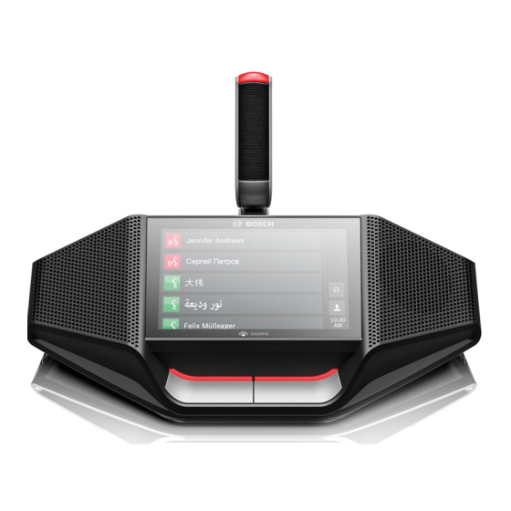
| Mechanical installation of Contribution Devices DICENTIS Mechanical installation of Contribution Devices The DICENTIS (tabletop and flush-mounted) devices are used to: – participate in a meeting or conference. – monitor and control a meeting or conference (chairperson use, depending on the configuration). - Page 57 This equipment is intended for environment Class A. DCNM-D / DCNM-DVT / DCNM-DSL / DCNM-DE Figure 7.2: Front, top, rear and side views Item Description Two‑way loudspeaker. Bosch Security Systems B.V. 2021.01 | V2.2 | Hardware Installation Manual...
- Page 58 Cable guides. – DCNM-DE, DCNM-DVT and DCNM-DSL are compliant with the Radio Equipment Directive (RED) 2014/53/EU. – Operating frequency is 13.56 MHz. Maximum field strength is -8.4 dBµA/m @ 10m. 2021.01 | V2.2 | Bosch Security Systems B.V. Hardware Installation Manual...
- Page 59 The star configuration makes use of connectors underneath the devices, ensuring for a neat, tidy system installation, especially advantageous for TV coverage. To connect the system network cables to the DICENTIS devices (refer to the following figure): Insert the system network cable/connector (2).
- Page 60 | Mechanical installation of Contribution Devices DICENTIS Figure 7.4: Bottom view DICENTIS devices (DCNM-D / DCNM-DVT / DCNM-DSL / DCNM-DE) Item Description Screw insert for fixed installation. 2x RJ45 connection input/output for system power cable. Cable guides. USB connector, for future use (DCNM-MMD / DCNM-MMD2 only).
-
Page 61: Dicentis Flush-Mounted Devices
DICENTIS Mechanical installation of Contribution Devices | en DICENTIS flush-mounted devices DCNM-FSL Item Description LCD screen Capacitive touch screen 3.5 mm stereo jack for headphone Headphone volume control Language selection buttons – The DCNM-FSL display turns on when a headphone is connected. - Page 62 Use the block-mounting method to install flush-mounted devices in surfaces with a thickness > 2 mm. The block-mounting method uses the DCNM-FEC Flush end caps, the DCN-FCOUP Couple Pieces and the DCN-FPT Flush positioning tool. 2021.01 | V2.2 | Bosch Security Systems B.V. Hardware Installation Manual...
- Page 63 DICENTIS Mechanical installation of Contribution Devices | en DCN-FPT >2 +0.5 R2.5 - 0.5 Bosch Security Systems B.V. 2021.01 | V2.2 | Hardware Installation Manual...
- Page 64 Notice! Install DCNM-FEC Flush end caps on the couple pieces at the two ends of the recess. Total NSF x (mm) 71.5 121.5 171.5 221.5 271.5 321.5 371.5 421.5 2021.01 | V2.2 | Bosch Security Systems B.V. Hardware Installation Manual...
- Page 65 Flush-mounted device DCNM-FSL Tab. 7.13: Number-size factors Removing a flush-mounted device To remove a flush-mounted device installed on a surface, use the DCNM-FET Flush extraction tools. DCNM-FET DCNM-FET DCNM-FET DCNM-FET Bosch Security Systems B.V. 2021.01 | V2.2 | Hardware Installation Manual...
-
Page 66: Dcnm-Fsl Flush Language Selector
Removing a flush-mounted device 7.2.1 DCNM-FSL Flush language selector Connect the language selector to a PoE switch in the DICENTIS network with a CAT-5e cable. External headphones socket You can connect an external headphones socket to the language selector (e.g. a 3.5 mm headphones socket). - Page 67 When using an external headphone connector, please install it according to the electrical diagram below (wiring and jack connector). X1426 HSJ2077 R1407 detect R1408 signal Figure 7.6: External headphone connector diagram Bosch Security Systems B.V. 2021.01 | V2.2 | Hardware Installation Manual...
- Page 68 Please note that this will cause the buttons' LEDs to be always on, which results in a shortened lifetime of the buttons' LEDs. 2021.01 | V2.2 | Bosch Security Systems B.V. Hardware Installation Manual...
-
Page 69: Dcnm-Idesk / Dcnm-Ideskvid Interpreter Desk
- B buttons - Press these 2 buttons (with a small raised dash) at the same time to enter the installation mode and assign the device to a booth and desk. See “DICENTIS Software manual”, chapter 9 on how to configure the interpreter desk. - Page 70 Two RJ45 compatible connections for system communication and power are available for quick and easy connection of the interpreter desks. Loop-through cabling can be applied by using DICENTIS System cables or star cabling using standard CAT-5e cables and PoE switches. Installing Interpreter desks The interpreter desks can be installed free-standing or fixed in more permanent installations (table-top) using mounting screws.
- Page 71 The HDMI outgoing current is limited at 60mA, while the official HDMI standard specifies 55 mA. Some HDMI to VGA converters may require more current, which may result in unexpected behavior or a non-working converter. Bosch Security Systems B.V. 2021.01 | V2.2 | Hardware Installation Manual...
-
Page 72: Dicentis Microphones
Lock-slider for lock release (Press and shift to release). Lock. Device female connector (see following figure). How to connect or remove the microphone The microphone can be easily connected to the DICENTIS devices: 2021.01 | V2.2 | Bosch Security Systems B.V. Hardware Installation Manual... - Page 73 Mechanical installation of Contribution Devices | en Figure 7.10: DCNM‑HDMIC or DCNM-MICS / DCNM-MICL connection To do so: Gently guide the connection guidance (4) into the DICENTIS device microphone connector (9). Gently push the connector plug (6) into the device microphone connector (9) until the connection lock (5) fits/click into place.
-
Page 74: Dcnm-Mmdsp Anti-Reflection Foil
| Mechanical installation of Contribution Devices DICENTIS DCNM-MMDSP Anti-reflection foil The DICENTIS anti‑reflection foil can be used to protect the tempered glass screen of a DICENTIS multimedia Device. Installation procedure Use the included alcohol swab and the microfiber fabric to clean the device LCD screen before installation. -
Page 75: Dcnm-Nch Name Card Holder
The name card holder (1) can be used to permanently display the participant’s name on the rear of a DICENTIS multimedia Device. The name card holder has two magnets (2) that allow it to be easily attached to, and removed from, the rear of the device. -
Page 76: Installation Test
Not to do so could result in a system malfunctioning. Each DICENTIS device has its own built‑in diagnostics, which can be used for faultfinding. The diagnostics starts as soon the DICENTIS device is powered on. The DICENTIS Conference System does not have to be configured with, and connected to, the system controller PC. - Page 77 DICENTIS Installation Test | en – Downloading devices is not covered in this manual. Refer to the DICENTIS configuration manual on how to download the devices. Customer service If a fault cannot be resolved, please contact your supplier or system integrator, or go directly to your Bosch representative.
- Page 78 | Installation Test DICENTIS 2021.01 | V2.2 | Bosch Security Systems B.V. Hardware Installation Manual...
- Page 80 Bosch Security Systems B.V. Torenallee 49 5617 BA Eindhoven Netherlands www.boschsecurity.com © Bosch Security Systems B.V., 2021 202102021655...