Table of Contents
Advertisement
Quick Links
Advertisement
Table of Contents

Related Manuals for Bosch D192G


Summary of Contents for Bosch D192G
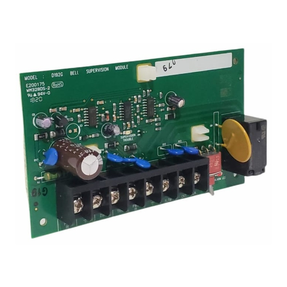
- Page 1 Notification Appliance Circuit Module D192G Installation manual...
- Page 3 Install, test and maintain the module according to these instructions, NFPA codes, local codes, and the authority having jurisdiction (AHJ). Failure to follow these instructions can result in failure of a detector to initiate an alarm event. Bosch Security Systems, Inc. is not responsible for improperly installed, tested or maintained devices.
- Page 4 This module is used for wiring connections to remote signaling devices. Wiring is supervised for open, short, or grounded circuit faults. You can connect up to 12 D192G modules to the same system on the control panels listed in the table below. For the individual annunciation of an indicating bell circuit, connect the modules to separate points.
- Page 5 5 Positive(+) connection to UL 864 10 Mounting holes certified power supply Warning! The D192G common (COM) terminals are digital ground, not earth ground. A ground fault condition exists when the COM terminals are connected to earth ground. Bosch Security Systems, Inc. Installation manual...
- Page 6 If the Alarm switch is in the SILENCE (OFF) position and the module is in alarm, both the SUPERVISION TROUBLE and ALARM LEDs light. Tab. 3.1: LED operation and troubleshooting 2020.05 | 04 | 4998122260 Installation manual Bosch Security Systems, Inc.
- Page 7 This resistor is included with the module. – For a supervised point, install a 1 kΩ EOL resistor across the COM and SUPV ZONE terminals on the last D192G module. Bosch Security Systems, Inc. Installation manual 2020.05 | 04 | 4998122260...
- Page 8 Maximum draw for each signaling device circuit is limited by the control panel power supply. – No more than 12 D192G modules per system. Power supplied by a remote power supply The auxiliary power supply must be a UL 864 Listed auxiliary 12 VDC or 24 VDC regulated, power-limited power supply for fire protective signaling units and commercial or residential burglary units.
- Page 9 5.1.1 Wiring interconnected loops with 12 VDC power supplied by the panel This wiring scheme allows up to 12 D192G modules (NAC loops) triggered by a single programmed alarm output. Figure 5.1: Wiring interconnected modules to a G Series panel supplying 12 VDC power 1 Last D192G module on the 6 1 kΩ...
- Page 10 This wiring scheme allows two separate strings of modules (NAC loops) triggered by separate programmed alarm outputs. Figure 5.2: Wiring separate module loops to a G Series control panel supplying 12 VDC power 1 Last D192G module on the 7 Connection to Relay A programmed interconnected NAC loop...
- Page 11 Wiring interconnected loops with 12 VDC or 24 VDC power supplied by an external power supply This wiring scheme allows up to 12 D192G modules (NAC loops) triggered by a single programmed alarm output. Figure 5.3: Wiring interconnected modules to a G Series panel with power supplied by an external power supply...
- Page 12 This wiring scheme allows two separate strings of modules (NAC loops) triggered by separate programmed alarm outputs. Figure 5.4: Wiring separate module loops to a G Series panel with power supplied by an external power supply 1 D192G modules on separate NAC 8 Negative (-) connection from external loops power supply and module COM to panel’s COMMON (not to earth...
- Page 13 5.2.1 Wiring interconnected loops with 12 VDC power supplied by the panel This wiring scheme allows up to 12 D192G modules (NAC loops) triggered by a single programmed alarm output. Figure 5.5: Wiring interconnected modules to a B Series panel supplying 12 VDC power...
- Page 14 This wiring scheme allows two separate strings of modules (NAC loops) triggered by separate programmed alarm outputs. Figure 5.6: Wiring separate module loops to a B Series control panel supplying 12 VDC power 1 Last D192G module on the 9 Connection between one module’s interconnected NAC loop...
- Page 15 Wiring interconnected loops with 12 VDC or 24 VDC power supplied by an external power supply This wiring scheme allows up to 12 D192G modules (NAC loops) triggered by a single programmed alarm output. Figure 5.7: Wiring interconnected modules to a B Series panel with power supplied by an external power supply 1 Last D192G module on the 9 Connection to module’s ALRM TRG...
- Page 16 This wiring scheme allows two separate strings of modules (NAC loops) triggered by separate programmed alarm outputs. Figure 5.8: Wiring separate module loops to a B Series panel with power supplied by an external power supply 1 Last D192G module on the 11 Positive (+) connection from one interconnected NAC loop relay’s COM terminal to the aux and...
- Page 17 19 1 kΩ EOL resistor (P/N: F01U011298) SUPV ZONE and panel zone 10 Connection between both module’s COM terminals, the power supply’s negative (-) terminal, and the panel’s digital COM (not to earth ground) Bosch Security Systems, Inc. Installation manual 2020.05 | 04 | 4998122260...
- Page 18 For instructions on programming the control panel, refer to the panel's Program Entry Guide. For compatibility information about synchronization modules and strobes, refer to the panel's Approved Applications Compliance Guide. 2020.05 | 04 | 4998122260 Installation manual Bosch Security Systems, Inc.
- Page 19 12 VDC supplied by the control panel’s AUX PWR terminal for special applications. Mechanical Dimensions (LxWxD) 5 in. x 3 in. x 0.75 in. (12.7 cm x 7.6 cm x 1.9 cm) Bosch Security Systems, Inc. Installation manual 2020.05 | 04 | 4998122260...
- Page 20 | Specifications Notification Appliance Circuit Module 2020.05 | 04 | 4998122260 Installation manual Bosch Security Systems, Inc.
- Page 22 Bosch Security Systems, Inc. Bosch Sicherheitssysteme GmbH 130 Perinton Parkway Robert-Bosch-Ring 5 Fairport, NY 14450 85630 Grasbrunn Germany www.boschsecurity.com © Bosch Security Systems, Inc., 2020...