Table of Contents
Advertisement
Advertisement
Table of Contents

Related Manuals for Bosch Dexter Tow Assist


Summary of Contents for Bosch Dexter Tow Assist
- Page 1 INSTALLATION MANUAL TOW ASSIST ABS & SWAY MITIGATION SYSTEM www.dexteraxle.com...
-
Page 2: Table Of Contents
Mounting Location on the Trailer .........4 CAUTION Mounting Orientation & Accuracy ........4 ECU Orientation Requirements ...........4 The Dexter Tow Assist system should only be installed by a qualified Recommended ECU Mounting Hardware ......4 technician. Recommended ECU Mounting Technique ......4 Installation steps listed in this manual are not meant to cover every trailer type, but provide the required elements needed to install the Tow Light Module Mounting Location .........5... -
Page 3: Tow Assist Brake Control Module - "Ecu
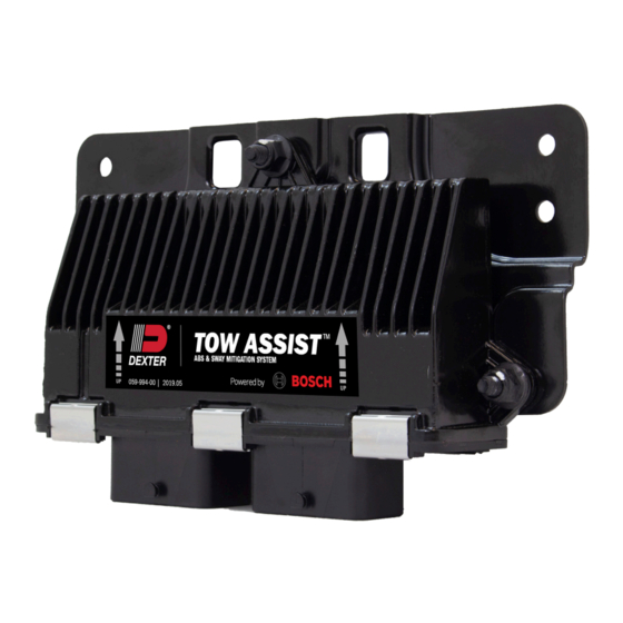
Tow Assist Brake Control Module - “ECU” Mounting Examples Below is a model of the Tow Assist Brake Control Module. This will be It is mandatory to provide an adequate solution to protect the ECU, referred to throughout the manual as the ECU (Electronic Control Unit). axle/power harness against road debris or vertical impact. -
Page 4: Mounting Location On The Trailer
Mounting Location on the Trailer ƒ The ECU should be mounted so the top edge of the Universal Mounting Bracket is parallel to the chassis or carrying surface The recommended mounting location for the ECU is shown below: of the unit. When mounted on a finished unit this should place the X and Y axis no more than ±5°... -
Page 5: Light Module Mounting Location
Light Module Mounting Location CAUTION The Tow Assist uses an indicator light module to notify the driver of system function and potential diagnostic codes. Driver notification is Proper harness must be used based on number of axles in an essential part of a safety system. The light module does not have installation. -
Page 6: Harness Routing Overview
Harness Routing Overview Diagram for Tow Assist wiring only. Additional wiring to connect the tow vehicle is still required. This is for illustration only, not exact routing locations. Brake Request Wire Lead Indicator Lamp Harness Ground Wire Lead ... -
Page 7: Power Harness
Power Harness ƒ Route the harness as desired avoiding tight bends and excessively sharp edges locating the power wires, light harness The power harness is designed to allow routing down the left side of the and OBD2 extension. Route it through the cable clamp at the trailer from the ECU. -
Page 8: Additional Installation Steps
ƒ Insert the PLUG A connector to the right side PLUG A receptacle CAUTION and secure the connector latch. The latch locks on a feature on the wire retention cap as identified. Make sure there is no Failure to connect Common Ground Wiring Point will cause loss orange seal sticking out of connector. -
Page 9: Ecu Initial Start Up
Mount the OBD2 connector securely using appropriate screws per When the ECU is CORRECTLY configured and power is applied, the application. system starts as follows: ƒ The indicator light will have two short color alternating bursts. This is the ECU checking for light presence. ƒ... -
Page 10: Configuration From Saved File
2. When no configuration is loaded, the program start screen will 4. After configuration selections have been made, click the Save look like the image below. Config button. Type in the desired file name and hit save. File type must remain as (*.cfg). 3. - Page 11 1. Open configuration and select the appropriate configuration 5. After Connect button clicked the program talks to the ECU and file. the Tow Assist system will flash both colors on the Indicator light while the PC is talking to Tow Assist ECU. The data in blue appears showing the current data in the ECU.
-
Page 12: Verification Startup After Configuration
Advanced Software Capabilities 8. ECU now configured and typically production personnel will hit Enter key or click Disconnect button. The indicator light will go ECU Status out and the cable can be removed. While connected to an ECU click on the ECU Status tab to see the six data fields available including the VIN that has been configured and the number of miles the ECU has logged. -
Page 13: Reference
Reference Figure 3: Example of Tandem Axle Harness and 30’ Power Harness OBD2 Connector Indicator Light Power/Indicator Light Harness Front Axle External Load Connector WSS Connector Yellow Left Magnet Connector Side Indicator Rear Axle TOW ASSIST INSTALLATION MANUAL 2021.01 | 13 ABS &... -
Page 14: Limited Warranty
LIMITED WARRANTY Limited Warranty What Products Are Covered any specific Dexter recommendations, including those specified in Dexter’s current manuals. All Dexter® Axle Company (“Dexter”) trailer axles, suspensions, and brake control systems manufactured on or after September 1, 2016, excluding Exclusions Dexter 6000 series Manufactured Housing Axles. -
Page 15: Ecu Mounting Template
ECU Mounting Template Make sure this template is printed to scale and the holes line up to the ECU before drilling into trailer. NOTE: THE Universal Mounting Bracket SHOULD NOT CONTACT THE FLOOR. Allowance of 1/8” air gap is appropriate to avoid unwanted vibration and damage to the ECU. - Page 16 www.dexteraxle.com 2900 Industrial Parkway East - Elkhart, IN 46516 Phone: 574-295-7888 - Fax: 574-295-8666 ISO 9001:2015 Certified 2021.01 © 2021 Dexter Axle Company. LIT-020-00...