
Related Manuals for Sony RCP-3100


Summary of Contents for Sony RCP-3100
- Page 1 5-001-747-11 (1) Remote Control Panel Operating Instructions Before operating the unit, please read this manual thoroughly and retain it for future reference. RCP-3100 © 2018 Sony Corporation...
-
Page 2: Table Of Contents
Configuring from the Web Menu ......17 Network security Web Configuration Connection Example ......17 SONY WILL NOT BE LIABLE FOR DAMAGES OF ANY KIND Setting Up Web Access ..........17 RESULTING FROM A FAILURE TO IMPLEMENT PROPER Web Menu Example ............18 SECURITY MEASURES ON TRANSMISSION DEVICES, Web Menu Operation ............20... -
Page 3: Overview
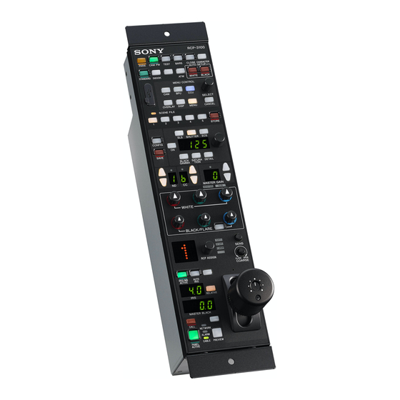
Features buttons and knobs of the unit. The RCP-3100 is a remote control panel for configuring and RCP ASSIGN knob controlling Sony studio and broadcast cameras. Up to five In a multi-camera system, you can change the device to units can be mounted in a 19-inch EIA rack. - Page 4 PC Control mode connection example HXC-FB80 HXCU-FB80 RCP-3100 CNS: PC Control cable IP address: 192.168.0.1 PC IP address: 192.168.0.201 CCU No.: 1 LAN cable CNS: MCS IP address: 192.168.0.101 Master IP address: 192.168.0.201 CNS: PC Control cable RCP No.: 6 IP address: 192.168.0.2...
- Page 5 MCS mode connection example Master device MSU-1500 CNS: MCS CNA-1 IP address: 192.168.0.201 Master/Client: Master Device No.: (1) RCP-3100 HDC3100 cable HDCU3100 cable cable CNS: MCS IP address: 192.168.0.1 Master IP address: 192.168.0.201 CCU No.: 1 CNS: MCS IP address: 192.168.0.101 Master IP address: 192.168.0.201...
-
Page 6: Supported Devices
Supported Devices Names and Functions of This unit supports connection to the following devices. Parts • HXC-FB75/HXC-FB80/HXC-P70 • HXCU-FB70/HXCU-FB80/HXCU-TX70 • HSC300RF/300R/100RF/100R • HSCU300RF/300R • HDC1700/2500 series Operation Panel • HDCU2000/2500 series • HDC4300 • HDC-P43 • HDCU4300 • HDCU3100/3170 Camera/panel •... - Page 7 b CAM PW (camera power) button when adjustment is finished. Pressing it again while Press this button to supply power from the CCU to the camera. adjustment is in progress will stop automatic adjustment. The button flashes to indicate the function is stopped. Press again Lighting state Meaning to stop the flashing indication.
- Page 8 Function control block 2 Multi-function block a SLS/SHUTTER/ECS selection buttons These select the operating mode of the electronic shutter. The buttons will not light when pressed if the camera does not have an electronic shutter function. b Adjustment knob Turn the adjustment knob to adjust the value displayed in the adjustment display window.
- Page 9 d CC (color temperature conversion) filter selection Adjustment block buttons These are lit when the unit has control permission for the CC filter. When they are not lit, the camera has the control permission. Pressing either the top or bottom button once switches the control permission to the unit.
- Page 10 2 Iris/master control black adjustment block The button is lit in relative value mode. Relative value mode (RELATIVE button is lit) The iris and master black are adjusted relative to initial values set at the positions of the IRIS control lever and master black control ring when the RELATIVE button is turned on.
-
Page 11: Connector Panel
a NETWORK indicator Connector Panel Displays the status of the network connection. Lighting state Meaning Note Connected with control device. When power is supplied from the CCU/CNU connector or EXT Flashing Cannot find control device. I/O connector, disable the PoE power from the network Cannot connect to the camera network, or legacy connector. -
Page 12: Mounting
Mounting Settings Precautions when Connecting Setting the Control Panel Connect the unit to ground in the following case. Settings can be configured directly from the unit or via the web • When connected by LAN cable only menu. The term “web menu” in this document refers to the setup To ground the rear side of the unit screen displayed by accessing the device from a web browser on a personal computer. -
Page 13: Configuring Directly From The Control Panel
For details about the numbers displayed in the CC filter Configuring Directly from display window, see “Control Panel Settings” (page 14). Note the Control Panel The CC filter selection buttons may not be required, depending on the item being set. In this case, proceed to step 4. -
Page 14: Control Panel Settings
Control Panel Settings Legend Default values are shown underlined. Item Sub item Adjustment display window Remarks Initialization (Master gain display window) (CC filter display window) value category * Connection Mode (CNS) – 0: Legacy, 1: Bridge, 2: MCS Network (01) IP Address Block 1 0 to 255 192... - Page 15 Item Sub item Adjustment display window Remarks Initialization (Master gain display window) (CC filter display window) value category * Sound MASTER volume 0 to 99 50 Other (11) CALL sound 1 to 15 1 You can preview the sound Other by pressing the ON button.
- Page 16 Item Sub item Adjustment display window Remarks Initialization (Master gain display window) (CC filter display window) value category * Date/Time Year – – (20) Month – – – – Hour – – Minute – – Second – – – Time Zone –11 to 11 0 ALL Preset Initialize all settings other...
-
Page 17: Configuring From The Web Menu
Configuring from the Web Menu The settings of the unit and assignable functions can be configured and checked using a web browser. Note Use the Google Chrome web browser on Windows. Web Configuration Connection Example PoE hub LAN cable LAN cable PC configuration IP address: 192.168.0.250 Subnet Mask: 255.255.255.0... -
Page 18: Web Menu Example
Web Menu Example [Switch Assignment] page All pages, other than the [Backup and Restore] page, are similar in operation. a [Configuration Mode] Set to ON to enable configuration of items. Settings can be only viewed when set to OFF. b [Find Device] button The button toggles between on and off with each press. - Page 19 [Backup and Restore] page a Factory Preset (Except Network Settings) [Execute] button Restore all settings other than network settings to the factory default settings. b [Other than Network] [Save to PC] button Back up all settings other than network settings to a file on a personal computer. [Load to RCP] button Load a file containing all settings (other than network settings) saved on a personal computer into the unit.
-
Page 20: Web Menu Operation
Web Menu Operation Enter the IP address of the unit in the web browser of a personal computer to access the unit. Immediately after accessing the web menu, [Configuration Mode] is set to OFF and the menu is in view mode. Click [ON] in [Configuration Mode]. -
Page 21: Web Menu Settings
Web Menu Settings Legend Default values are shown underlined. Category Item Sub item Configuration range (default setting) Initialization category Information – (Information display only) – – Network TCP/IP IP Address 0 to 255 Network System Subnet Mask 0 to 255 Network Settings Default Gateway... - Page 22 Category Item Sub item Configuration range (default setting) Initialization category Extend Call ON/OFF ON, OFF Other Configuration 2 Extend Time 1 to 60 sec. 3 sec. Other Mode Always Extended, Not Own Call Extended, Other Only Camera Call Extended VR Setting IRIS 1/1, 1/2, 1/4 Other...
-
Page 23: Specifications
External dimensions (Unit: mm (inches)) EXPIRATION OF THE WARRANTY, OR FOR ANY OTHER REASON WHATSOEVER. 2- ∅5 ( • SONY WILL NOT BE LIABLE FOR CLAIMS OF ANY KIND 125 (5) 80 (3 MADE BY USERS OF THIS UNIT OR MADE BY THIRD 67 (2 PARTIES. -
Page 24: Open Source Software Licenses
To meet the requirements of the software copyright holders, Sony is obligated to inform you of the content of these licenses. For the content of these licenses, see the PDF files in the “License”...