Table of Contents
Advertisement
Advertisement
Chapters
Table of Contents

Related Manuals for Panasonic NS1000


Summary of Contents for Panasonic NS1000
- Page 1 NS1000 CLASSROOM MATERIAL (TRAINER)
- Page 2 Introduction This material refers to the KX-NS1000 PBX system, and details the basic information that should be covered in a classroom session (1 day) The Session comprises of the following sections; NS1000 – Installation & Initialisation NS1000 – WebMC NS1000 – Terminal Registration NS1000 –...
- Page 3 Section - 1 INSTALLATION AND INITIALIZATION...
- Page 4 Introduction This material refers to the KX-NS1000 PBX system, and details the basic steps necessary to install and initialize the unit. The Module comprises of the following sections; NS1000 – Installation NS1000 – System Initialization From following this course element, participants will be gain an understanding of how to install and initialize the NS1000 ready for first use.
-
Page 5: Table Of Contents
Contents Chapter 1 Installation 1.1 Unpacking 1.2 Component Location 1.3 Option Installation 1.4 Rack Mounting 1.5 Desk Mounting 1.6 Wall Mounting 1.7 Earth / Surge Protector connection 1.8 Connecting Power 1.9 External Connections Chapter 2 System Initialization 2.1 System Initialization 2.2 Web Console Preparation 2.3 Web Console Connection 2.4 1... -
Page 6: Chapter 1 Installation
Chapter 1 INSTALLATION... - Page 7 NOTE IMPORTANT: Before installing the NS1000 system, refer to the Installation Manual. The Installation Manual contains specific information regarding the safe installation of the unit and also details specific installation and wiring precautions. The information contained in this presentation is intended to supplement the NS1000 Installation Manual by providing an overview of the installation and initialization process and in no way replaces the published Installation Manual.
-
Page 8: Unpacking
1.1 Unpacking (1) Unpacking Remove the NS1000 from the box and check that the following items are present; Description Quantity NS1000 Main Unit AC Cord 19” Rack-mounting bracket AC Cord Hook Clip Screws... -
Page 9: Component Location
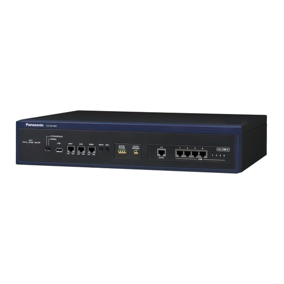
1.2 Component Location (1) Component location (External) The main ports, jacks and LEDs etc are shown below; Front Side LED indicators MOH/EPG ports DPH Port (Option) Legacy Slot (Option) System mode SW USB port IP ports Back Side AC SW GROUND Serial port AC cord clamp... - Page 10 1.2 Component Location (2) Component location (Internal) The expansion/option slots are shown below; Slot (Doorphone) Slot (FAX Server) Slot (Trunk/SLT) Slot (Storage Memory) Slot Slot (DSP 2) (DSP 1)
-
Page 11: Option Installation
1.3 Option Installation (1) Option Installation • Optional cards can be installed when the top cover is removed. • Option Cards are not “Hot-Swap” • Power must be removed from the unit before optional cards are installed 1. Ensure the Power Switch is ‘OFF’... - Page 12 1.3 Option Installation (2) Option Installation The required options can now be installed. 3. Remove the cover 4. Install the required options 5. Replace the top cover and screws. CAUTION: When installing or removing option cards, do not put pressure on the main board. Damage to the option and main board may result.
-
Page 13: Rack Mounting
Rack Mounting the NS1000 The NS1000 can be rack-mounted using the supplied brackets and screws. 1. Mount the brackets onto the NS1000. 2. Bolt the NS1000 into the rack using the hardware supplied by the rack manufacturer. Size = 2U Dimensions: 430mm×88mm×340mm... -
Page 14: Desk Mounting
1.5 Desk Mounting Desk Mounting the NS1000 The NS1000 can be installed on a flat surface. • The unit MUST be placed flat on it’s base (Not on it’s back, sides or upside-down etc) • The units FAN opening MUST be clear •... -
Page 15: Wall Mounting
1.6 Wall Mounting Wall Mounting the NS1000 The NS1000 can be installed onto a suitable wall using the optional Wall Mounting kit. (Refer to the Installation Manual for further details) Install the screws Mount the unit to the wall (with suitable wall anchors etc) (using the Wall Mounting Kit) NB: The unit must be installed with the arrows on the Wall Mounting brackets pointing “UP”. -
Page 16: Earth / Surge Protector Connection
1.7 Earth / Surge Protector connection Frame Ground (Earth) and Surge Protection (Refer to the Installation Manual!) Frame Ground Surge Protection WARNING • Proper connection to earth is very important to reduce the risk to the user of electrocution or to protect the PBX from the effects of external noise or lightning strike. -
Page 17: Connecting Power
1.8 Connecting Power Connecting the AC Cord Using the AC Cord supplied with the unit, connect it to the PBX and secure with the supplied AC Cord Clip. Connect the other end of the AC Cord to the UPS System AC Cord Clip UPS System: A UPS should be connected to the PBX to provide temporary in the event of a power failure. -
Page 18: External Connections
1.9 External connections Connecting Peripherals and Options Once the NS1000 has been mounted, various peripherals and options can be connected. (Refer to the Installation Manual for further details) - Page 19 Chapter 2 SYSTEM INITIALISATION...
- Page 20 2.1 System Initialisation After installing the option cards, initialize the system (factory default settings) 1. Ensure the power switch is OFF. 2. Slide the System Mode Switch to the “SYSTEM INITIALIZE” position. System Mode Switch 3. Turn the power switch ON. (STATUS and MASTER LED will flash AMBER), the STATUS LED will then flash GREEN.
-
Page 21: Web Console Preparation
2.2 Web Console Preparation Below are the system requirements necessary for Web Connection to the NS1000 PC Requirements Minimum Recommended 1.0GHz Intel Pentium/Celeron processor, or Intel Core 2 Duo/3.2GHz Intel Pentium/ Celeron higher spec CPU processor, or higher spec CPU... -
Page 22: Web Console Connection
Connecting a PC to the NS1000 via the Web-MC DHCP Client DHCP Server Set your PC as a DHCP Client (Automatically Obtain IP Address.) Connect your PC to the MNT Port of the NS1000 (Default IP Address 223.0.0.1) Open you Browser and enter the URL http://223.0.0.1/WebMC The Web Maintenance Console login screen will then be displayed in your browser. -
Page 23: St Login
2.4 First Login (Factory Default Setting) When connecting to the system for the first time, the Easy Setup Wizard will launch. 1st Login (The PBX is in the factory default state) Default Settings: Username: INSTALLER Password: 1234 2. Click Install 1. -
Page 24: Easy Setup
2.5 Easy Setup (1) Location Setting 1. Set the unit status (Master/Slave), Suffix and Area Set the unit as Master or Slave. Set the unit Suffix Code (UK, NE, CE, GR etc) and your required country. Click ‘Next’ to continue. The Suffix Code can be found on the units Nameplate and box... - Page 25 2.5 Easy Setup (2) PBX Setting 2. Give the system an appropriate name and set the Time Zone Use a name which easily identifies the unit. Select the Time Zone. The Local date and time are obtained automatically from your PC. Check that the PC date/time is correct.
- Page 26 2.5 Easy Setup (3) LAN Setting 3. Enter the required LAN Settings By default, the PBX uses a static IP Address (Recommended) By default, no DNS server addresses are set. Configure them as required. By default, the DSP Cards use DHCP to obtain an IP- Address, however static addresses can also be assigned.
- Page 27 2.5 Easy Setup (4) LAN Setting 4. Enter the IP Terminal Registration Mode setting and select if ‘One-Look’ Trial should start. There are three terminal registration Modes; Manual: Suitable for all supported IP Terminals and network configurations. Registration information is set manually in the Terminal and PBX. (This is the recommended setting when a range of IP/SIP Terminals will be used with the system.) Full Automatic:...
- Page 28 2.5 Easy Setup (5) SNTP (Simple Network Time Protocol) / Daylight Saving Setting 5. The source used for automatic time adjustment and the Daylight Saving mode is set here. This is useful to keep the time displayed on the terminals and SMDR records etc accurate. Automatic Time Adjustment can be made using ISDN/Analogue Trunks (ISDN/FSK) or via a...
- Page 29 2.5 Easy Setup (6) Maintenance / Remote Management Settings 6. The Installer Password can be changed (Strongly Recommended) and SNMP (Simple Network Management Protocol) can be configured here. Be sure to change the default Installer password up installation. Use a strong password. Check the required SNMP settings with the Network Administrator and enter as...
- Page 30 2.5 Easy Setup (7) If the systems LAN settings were changed during Easy Setup, you will be prompted to restart the PBX so that the changes can take effect. Be sure to login with the new password etc 2nd Login (Easy Setup has been completed) Login with the new password.
- Page 31 2.5 Easy Setup (8) By Default, the WebMC portal will remain active (without activity) for 60 minutes. To change the WebMC Portal settings, change the time here after 2nd login :- Settings To change the WebMC Auto Logout Network Service timer –...
-
Page 32: Slave Initial Configuration
Chapter 3 SLAVE INITIAL CONFIGURATION... - Page 33 3.1 Slave Initial Configuration Location Setting 1. Set the unit status as Slave. 2. Enter the IP Address of the Master System. Set the unit as Slave. Enter the IP Address of the Master Unit. Default IP Address: 192.168.0.101 Click ‘Next’ to continue.
- Page 34 3.1 Slave Initial Configuration LAN Setting 3. Enter the required LAN Settings. Change the IP Address to a different number within the same range Change the IP Address to a different number within the same range Click ‘Next’ to continue. Note: If you are Not using DHCP then you Must assign a DSP IP Address Manually.
- Page 35 3.1 Slave Initial Configuration LAN Setting Note: Once the LAN settings has changed, the system will need to reboot. The bellow pop-up will be displayed. Click OK to reboot system.
- Page 36 3.1 Slave Initial Configuration Registration Setting 4. Enter the IP Terminal Registration Mode as Manual. Full automatic can be used but is not covered in this document. Manual entry reduces the number of Empty Extension numbers in CA. Activate the 60-day One- Look Trial if required.
- Page 37 3.1 Slave Initial Configuration SNTP (Simple Network Time Protocol) / Daylight Saving Setting 5. The source used for automatic time adjustment and the Daylight Saving mode is set here. This is useful to keep the time displayed on the terminals and SMDR records etc accurate. Automatic Time Adjustment can be made using...
- Page 38 3.1 Slave Initial Configuration Maintenance / Remote Management Settings 6. The Installer Password can be changed if required. Even if you want to keep as default (1234) you must re-enter it here before continuing. Even if you want to keep the default password you must re- enter it before continuing.
- Page 39 3.1 Slave Initial Configuration If the systems LAN settings were changed during Easy Setup, you will be prompted to restart the PBX so that the changes can take effect. Be sure to login with the new password etc 2nd Login (Easy Setup has been completed) Login with the new password.
-
Page 40: Slave Registration
3.2 Slave Registration Once the both systems have been initially configured, the Slave system needs to be added to the Master system network. Log into the Master system. You will be presented with the bellow screen. Click on the Add Site Button. Add Site Follow the prompts to add the desired Slave site. - Page 41 3.2 Slave Registration Once the Slave system has been added to the network, the Slave system needs to be registered to the Master system. Log into the Master system. You will be presented with the bellow screen. Click on the List button. List View...
- Page 42 3.2 Slave Registration Click on the Registration button. From the popup, select the Slave system displayed in the list and click Next. Click on Registration Select Slave Unit Select move button Click Next...
- Page 43 3.2 Slave Registration Once the Slave is registered, it will show in the list view. Pressing the Home button will show the systems in the Tree view. This is displayed on the next slide.
- Page 44 3.2 Slave Registration Once the Slave has been registered, it will show on the Home screen (In-Service).
- Page 45 Chapter 4 UPS CONNECTION...
-
Page 46: Ups Connection And Setting
4.1 UPS Connection and setting (1) UPS (Uninterruptible Power Supply) Integration Description An uninterruptible power supply unit (UPS) is a device that supplies power for several minutes to a connected device when a power failure occurs. If the PBX is connected to a compatible UPS via USB when a power failure occurs, the PBX can determine how much power remains in the UPS and shut down when the remaining power drops below a specified amount to prevent data loss or corruption. - Page 47 4.1 UPS Connection and setting (2) 1. Connect the UPS as described in the Installation manual 2. Set the NS1000 Shutdown threshold via the WebMC Maintenance -> Status -> Equipment Status -> 1. UPS UPS Status can be seen here...
- Page 48 SYSTEM INITIALIZATION COMPLETE...
- Page 49 Section - 2 WEB MAINTENANCE CONSOLE...
- Page 50 Introduction Web Maintenance Console (Web MC) All features and settings of the PBX can be set through system programming with the Web Maintenance Console. The following explains the installation procedure, basic structure and operation of the WebMC.
- Page 51 Contents Chapter 1 Overview 1-1. Web Maintenance Console 1-2. Operating Modes 1-3. User’s Account Chapter 2 Connections 2-1. System Requirements 2-2. Available Connections 2-3. Accessing Web MC 2-4. Logging into Web MC Chapter 3 WebMC – Tour 3-1. Screen Descriptions 3-2.
-
Page 52: Chapter 1 Overview
Chapter 1 OVERVIEW... -
Page 53: Web Maintenance Console
1-1. Web Maintenance Console - Overview There is only one Programming Tool for KX-NS1000. The NS1000 WebMC is a web-based application which allows you to manage the PBX system easily. • KX-NS1000 does NOT support Unified PC Maintenance Console (UPCMC) for KX-NCP/TDE/TDA. -
Page 54: Operating Modes
1-2. Operating Modes There are two programming modes; Interactive Mode & Batch Mode • Interactive Mode (Allows real-time access and configuration of the PBX system.) •Direct Connection (http) •Via LAN (http) •Via VPN (http) •Via Internet (https) • Off-Line Mode (Configuration is done Off-Line and applied to the PBX at a later date.) Available 2012 •Direct Connection (http) •Via LAN (http) - Page 55 1-3. User Accounts Account Levels The WebMC supports 3 different account types (Access Levels). The number of users who can simultaneously login to the system are shown below. Account Levels Level Description Installer Dealers and For all system programming settings. system installers “Installer”...
-
Page 56: Chapter 2 Connections
Chapter 2 CONNECTIONS... -
Page 57: System Requirements
2-1. System Requirements System Requirements Requirements Descriptions - Windows XP Both 32bit and 64bit version is available. - Windows Vista Business - Windows 7 Professional 100MB of available hard disk space Minimum Requirements Display -Screen resolution: XGA (1024 * 768) Recommended Settings -DPI setting: Normal size (96 DPI) Browsers... -
Page 58: Available Connections
2-2. Available Connections (1/3) In order to program or manage the PBX, you need to connect your PC to the PBX. Several connection methods are provided, and here you can see the outline of the direct connection. 1. Direct Connection (MNT Port) Set the PC as a The MNT port is set as a DHCP server. - Page 59 2-2. Available Connections (2/3) It is also possible to manage the PBX via a LAN or VPN connection. 2. LAN/VPN Connection (LAN Port) • Via LAN • Via VPN Switch Switch - 10BASE-T/100BASE-TX: CAT 5 or higher - 1000BASE-T: CAT 5e or higher - Maximum length: 100 m - Auto Negotiation: ON - If using VLAN:...
- Page 60 - 1000BASE-T: CAT 5e or higher - Maximum length: 100 m - Auto Negotiation: ON - If using VLAN: The switch must be IEEE 802.1Q compliant, and set the port to “Untagged”. The WAN port on the KX-NS1000 is not supported with ver. 1.0.
-
Page 61: Accessing Web Mc
There are different addresses depending on Connection Types: 1. When Connecting via MNT Port http://kx-ns1000. (or http://223.0.0.1) Be sure to include the period (.) at the end as shown. “223.0.0.1”: the default IP address of the MNT port = Fixed 2. - Page 62 2-4. LOGIN / LOGOUT (1) LOGIN After establishing a connection to Web Maintenance Console, the login window is displayed, and a login name and password must be entered. Login Restrictions • Up to 33 users may log in at one time to Web Maintenance Console. However, only 1 user may change PBX system settings at a time.
- Page 63 2-4. LOGIN / LOGOUT (2) LOGOUT Be sure to log out from the Web MC using the Logout button, otherwise any unsaved changes will be lost. Clicking this button will save any programming changes to the PBX’s Storage Memory Card and log you out of Web Maintenance Console.
-
Page 64: Chapter 3 Webmc - Tour
Chapter 3 WEBMC - TOUR... -
Page 65: Screen Descriptions
3-1. Screen Descriptions (1/4) Upon LOGIN, you are presented with the ‘Home’ Screen Home Screen Icon Loads the Home screen. PBX Slaves Displays the Maintenance screen. Displays the Setup screen. Saves the data. Opens the on-line help. Displays the Web MC version info. PBX Maser Saves the data and logs you out. - Page 66 3-1. Screen Descriptions (2/4) Using the ‘List’ view in the ‘Home’ Screen allows you to see the PBX Type (Master/Slave), IP-Address, MAC address, S/W Version and Region type of all PBXs in a One-Look system. List View PBX Status PBX System Information is shown here.
- Page 67 3-1. Screen Descriptions (3/4) Setup Screen Setup Screen Icon Connected Site Setup Screen Tree Items Item Primary Functions Users • Manage, view, and add PBX user profiles and account information PBX Configuration • Configure PBX hardware settings for cards, equipment, and networking •...
- Page 68 3-1. Screen Descriptions (4/4) Maintenance Screen Maintenance Screen Icon Maintenance Screen Tree Items Item Primary Functions Status • Check the status of the PBX’s system hardware • Check the status of PBX equipment (PSs, CSs, UPS, etc.) • Check the status of extensions used by the Unified Messaging system System Control •...
-
Page 69: Button Descriptions
3-2. Button Descriptions (1/2) Standard Buttons Temporarily saves changes to DRAM and closes the current screen. Abandons changes and returns to the previous screen. Temporarily saves changes to DRAM and remains on the same screen. To save setting while programming, click this button on the Home screen. When this button is clicked to logout of Web Maintenance Console, system data is automatically backed up from the PBX to the Storage Memory Card. - Page 70 3-2. Button Descriptions (2/2) Each Setting screen has a number of helpful icons available. The available icons will differ, depending on the screen. Standard Icons Copies Data Fields Deletes the selected row Edits the selected row Adds new entry Remove filter...
-
Page 71: Slot View
3-3. Slot View In the ‘Settings’ View, the ‘SLOT’ view shows what Physical and Virtual cards are installed. May other system properties or features can also be viewed. ‘Settings’ -> PBX Configuration -> 1. Slot Select ‘Physical’ or ‘Virtual’ Slot View Status Buttons Installed ‘Physical’... -
Page 72: Chapter 4 Appendix
Chapter 4 APPENDIX... -
Page 73: Static Nat Setting Example
A-1 Static NAT Setting Example Setting Items Descriptions Interface WAN-side interface Protocol TCP or UDP Outside network port number ( 1 ~ 65535 ) Receiving Port No. (WAN side) IP Address of Transfer Destination (LAN Side) The destination IP address to which the packets are transferred. Port No. - Page 74 WEBMC COMPLETE...
- Page 75 Section - 3 TERMINAL REGISTRATION...
- Page 76 Introduction The NS1000 supports 3 methods of IP terminal registration. 1. Full Automatic Mode When an IP terminal is connected to the network, the IP terminal will automatically discover the main unit and an unallocated extension number will automatically assigned to the IP Terminal.
- Page 77 Contents Chapter 1 UT/NT Series Registration 1-0. NS1000 – DCHP Server Setting 1-1. Full Automatic Mode – Overview 1-2. PBX System Configuration Chapter 2 NT Series Registration 2-1. Extension Number Mode – Overview 2-2. PBX System Configuration Chapter 3 UT Series Registration 3-1.
- Page 78 Contents Chapter 5 DECT CS Installation 5-0. DECT CS Installation Chapter 6 Registration – Other Terminals 6-0. Registration 6-1. De-registration...
-
Page 79: Chapter 1 Ut/Nt Series Registration
Chapter 1 UT/NT SERIES REGISTRATION FULL AUTOMATIC MODE... -
Page 80: Ns1000 - Dchp Server Setting
1-0. NS1000 – DHCP Server setting The NS1000 can be configured as a DHCP Server. Where a 3rd party networked DHCP Server is not available, the NS1000 can be configured to provide DHCP Services. 1. Select ‘Settings’ View 2. Select ‘Network Service’ -> 1. DHCP Thank you ! 3. -
Page 81: Full Automatic Mode - Overview
1.1 ‘Full Automatic’ Registration Mode Full Automatic Mode – Overview When UT/NT PTs are connected to the NS1000 on the same network – Full Automatic Registration of the Terminals is possible. No manual setting of the PTs or PBX is required. -
Page 82: Pbx System Configuration
1.2 PBX System Configuration (1) Confirm the IP Terminal Registration Mode 1. Login to the Web-MC 2. Select ‘Setup’ 3. Select 1.1 ‘Slot’ -> ‘Site Property’ -> ‘Main’ 4. Confirm the system is in “Full Automatic” Mode. - Page 83 1.2 PBX System Configuration (2) Install a Virtual Extension card (V-IPEXT32 or V-UTEXT32) - 1 5. Select 1.1 ‘Slot’ -> ‘Virtual’ 6. Install the V-Ext Card...
- Page 84 1.2 PBX System Configuration (3) Install a Virtual Extension card (V-IPEXT32 or V-UTEXT32) - 2 7. Click ‘OK’ to install the V-Ext card. 8. Select ‘Port Property’.
- Page 85 1.2 PBX System Configuration (4) Confirming the available Extension Numbers. 10. When Registered, the Ext will show as INS 9. The Terminals will begin registering from the first available Ext Number.
-
Page 86: Chapter 2 Nt Series Registration
Chapter 2 NT SERIES REGISTRATION EXTENSION NUMBER MODE... -
Page 87: Extension Number Mode - Overview
2.1 ‘Extension Number’ Registration Mode Extension Number Mode – Overview When NT PTs are connected to the NS1000 on the same network – Registration of the Terminals, inputting only the desired Extension Number is possible. No manual setting of the PTs or PBX is required. -
Page 88: Pbx System Configuration
2.2 PBX System Configuration (1) Confirm the IP Terminal Registration Mode 1. Login to the Web-MC 2. Select ‘Setup’ 3. Select 1.1 ‘Slot’ -> ‘Site Property’ -> ‘Main’ 4. Confirm the system is in “Extension Input” Mode. - Page 89 2.2 PBX System Configuration (2) Install a Virtual Extension card (V-IPEXT32) - 1 5. Select 1.1 ‘Slot’ -> ‘Virtual’ 6. Install the V-IPEXT32.
- Page 90 2.2 PBX System Configuration (3) Install a Virtual Extension card (V-IPEXT32) - 2 7. Click ‘OK’ to install the V-IPEX32 card. 8. Select ‘Port Property’.
- Page 91 2.2 PBX System Configuration (4) Connect the NT Series IP-PT to the network (which includes DHCP Server) and input the desired Ext number via the IP-PT Keypad when prompted. Note: 9. Enter the desired Ext a.) If extension number is set in V-IPEXT32, but has no PT registration, the IP-PT will number and press ENTER automatically register to the first available Port/ Ext number (you will not be prompted to enter an Ext number from the PT.)
-
Page 92: Chapter 3 Ut Series Registration
Chapter 3 UT SERIES REGISTRATION ‘MANUAL’ MODE... -
Page 93: Manual Registration Mode - Overview
3.1 Manual Registration Mode Manual Mode - Overview When Terminals are connected to an NS1000 which exists on a different network, or a DHCP Server is not available – Registration of the Terminals must be carried out manually by entering the necessary Network/PBX IP Addresses. - Page 94 3.2 Manual Registration Mode – UT series 1. Registering an UT-PT to the PBX (Manual Registration Mode) When registering a UT without a local DHCP server OR when registering the UT from a remote location etc, you will need to enter the IP Address of the UT AND the IP Address of the PBX into the UT manually (Manual Registration Mode).
- Page 95 3.2 Manual Registration Mode – UT series 1. Registering an IP-PT to the PBX (Manual Registration Mode) – cont…. (UT-PT IP Address Setting) Information Display 3. Using the ‘Navi-Key’, select Network Settings ENTER ‘Network Settings’ and press ‘Enter’. Back Enter NAVI-KEY 4.
- Page 96 3.2 Manual Registration Mode – UT series. 1. Registering an IP-PT to the PBX (Manual Registration Mode) – cont…. (UT-PT IP Address Setting) 7. The Network address and MAC information Information Display can be confirmed by navigating back to the Network Settings ‘Information Display’...
- Page 97 3.3 PBX System Configuration (1) Confirm the UT Terminal Registration Mode (Manual) 2. Select ‘Setup’ Login to the Web-MC 3. Select 1.1 ‘Slot’ -> ‘Site Property’ -> ‘Main’ 4. Confirm the system is in “Manual” Mode.
- Page 98 3.3 PBX System Configuration (2) Install a Virtual Extension card (V-UTEXT32) - 1 5. Select 1.1 ‘Slot’ -> ‘Virtual’ 6. Install the V-UTEXT32 Card and set the number of users.
- Page 99 3.3 PBX System Configuration (3) Install a Virtual Extension card (V-UTEXT32) - 2 7. Click ‘OK’ to install the V-Ext card. 8. Select ‘Out Of Service’.
- Page 100 3.3 PBX System Configuration (4) Install a Virtual Extension card (V-UTEXT32) - 3 9. Select ‘Port Property’. 10. Set the Ext number and Password, then click ‘Apply’ NB: By Default, the extension Password is set to ‘1234’...
- Page 101 3.3 PBX System Configuration (5) Install a Virtual Extension card (V-UTEXT32) - 4 11. Set the port ‘In Service’. 12. Select ‘IP-Phone’ Registration -> ‘SIP-MLT’...
- Page 102 3.3 PBX System Configuration (6) Install a Virtual Extension card (V-UTEXT32) - 5 13. Select ‘Registration’. 14. Select the desired Extension 15. The UT Terminal will and follow the prompts. then register with the PBX.
-
Page 103: Registration Confirmation (Ut)
3.4 Registration Confirmation (UT) Confirm the registration 10 OCT. 12:09PM MON 11. After the UT-PT has re-booted and the WebMC Registration process has been completed, the UT-PT will be in-service. Setting Call Log Menu Further Extension configuration can now be made via the WebMC, using the Extension Number of the IP-PT. From the V-UTEXT32 Port Properties screen, the UT registration status, Password, MAC, IP-Address and firmware version can be seen. -
Page 104: Chapter 4 Nt Series Registration
Chapter 4 NT SERIES REGISTRATION ‘MANUAL’ MODE... -
Page 105: Manual Registration (Nt)
4.1 Manual Registration Mode – NT series 1. Registering an IP-PT to the PBX (Manual Registration Mode) When registering an IP-PT without a local DHCP server OR when registering an IP-PT from a remote location etc, you will need to enter the IP Address of the IP-PT AND the IP Address of the PBX into the IP-PT manually (Manual Registration Mode). - Page 106 4.1 Manual Registration Mode – NT series 1. Registering an IP-PT to the PBX (Manual Registration Mode) – cont…. (IP-PT IP Address Setting) 3. Using the ‘Navi-Key’, select Menu -> Network ‘Network’ and press ‘Enter’. IP Port STORE EXIT CONT ENTER DHCP Enable Disable 4.
- Page 107 4.1 Manual Registration Mode – NT series. 1. Registering an IP-PT to the PBX (Manual Registration Mode) – cont…. (IP-PT IP Address Setting) Menu Network 7. Using the ‘Navi-Key’, -> PBX select ‘PBX’ and press ‘Enter’. IP Port STORE EXIT CONT ENTER PBX IP Address ? 8.
- Page 108 4.2 PBX System Configuration (1) Confirm the IP Terminal Registration Mode 2. Select ‘Setup’ 1. Login to the Web-MC 3. Select 1.1 ‘Slot’ -> ‘Site Property’ -> ‘Main’ 4. Confirm the system is in “Manual” Mode.
- Page 109 4.2 PBX System Configuration (2) Install a Virtual Extension card (V-IPEXT32) - 1 5. Select 1.1 ‘Slot’ -> ‘Virtual’ 6. Install the V-IPEXT32 Card.
- Page 110 4.2 PBX System Configuration (3) Install a Virtual Extension card (V-IPEXT32) - 2 7. Click ‘OK’ to install the V-IPEX32 card.
- Page 111 4.2 PBX System Configuration (4) Setting Registration Mode - 1 9. Select ‘Port Property’. 10. Click ‘Registration’.
- Page 112 4.2 PBX System Configuration (5) Setting Registration Mode - 2 11. Select the desired Extension number and follow the prompts.
-
Page 113: Registration Confirmation (Nt)
4.3 Registration Confirmation – NT series When the NT-PT has been registered, it’s display will display the following information; 19 JUL. 10:14 12. After the IP-PT has re-booted and the WebMC Registration process has been completed, the IP-PT will be in-service. PROG INFO RING MENU Further Extension configuration can now be made via the WebMC, using the Extension Number of the IP-PT. - Page 114 Chapter 5 DECT CS INSTALLATION...
- Page 115 5-0. DECT CS Installation (KX-NCP0158CE) – (1) To assign a static IP Address to the KX-NCP0158CE IP-CS, the Panasonic UPCMC Tool is required. It is not possible to set a static IP Address on the IP-CS via the NS1000 WebMC.
- Page 116 5-0. DECT CS Installation (KX-NCP0158CE) – (2) Continued from previous slide...
- Page 117 5-0. DECT CS Installation (KX-NCP0158CE) – (3) Step 2 - Registering IP-CSs to the PBX Click [Setup] select [PBX Configuration] – [1.Configration] – [1.Slot] [IP Phone Registration] – [Option] or [Site Property] – [Main]...
- Page 118 5-0. DECT CS Installation (KX-NCP0158CE) – (4) Continued from previous slide Select “Manual” in “IP Terminal Registration Mode”, then click [Apply].
- Page 119 5-0. DECT CS Installation (KX-NCP0158CE) – (5) Continued from previous slide 1. Click [Setup] select [PBX Configuration] – [1.Configuration] – [1.Slot] select [Virtual]...
- Page 120 5-0. DECT CS Installation (KX-NCP0158CE) – (6) Continued from previous slide 2. Select [V-IPCS4]...
- Page 121 5-0. DECT CS Installation (KX-NCP0158CE) – (7) Continued from Previous slide 3. Select [Number of cards], then click [OK] Cancel...
- Page 122 5-0. DECT CS Installation (KX-NCP0158CE) – (8) Continued from previous slide 4. Select [Port property]...
- Page 123 5-0. DECT CS Installation (KX-NCP0158CE) – (9) Continued from previous slide 5. Click [Registration]...
- Page 124 5-0. DECT CS Installation (KX-NCP0158CE) – (10) Continued from previous slide 6. Select [IP-CS Index], then click [Next]...
- Page 125 5-0. DECT CS Installation (KX-NCP0158CE) – (11) Continued from previous slide 7. After Registration completed, then click [Close]...
- Page 126 Chapter 6 REGISTRATION – OTHER TERMINALS...
- Page 127 6-1. Registration – Other Terminals Other Terminals such as: • KX-NT700 (Conferencing Unit) • TCA/WT Series DECT Terminals • 3rd Party SIP Telephones Must all be registered using ‘Manual’ Registration mode. Notes: For KX-NT700 and 3rd Party SIP Telephones – ensure a V-SIPEXT32 (inc A/Ks) is installed. DECT Handsets (TCA/WT) are registered in the same manner as TDE/NCP PBX systems.
- Page 128 6-2. De-Registration (1) Registered Terminals can be de-registered from the system via the Virtual Cards ‘Port Properties’ 1. Select the De-Registration mode. Use ‘De-Registration’ mode when the Terminal is connected to the system and powered on. Use ‘Forced De-registration when the terminal is not connected to the system or is faulty.
- Page 129 6-2. De-Registration (2) After selecting the de-registration mode, select the desired extension and follow the prompts. When the de-registration process is complete, the display of the terminal will indicate that it is not registered. (Fault, Poor Connection etc)
- Page 130 TERMINAL REGISTRATION COMPLETE...
- Page 131 SECTION - 4 NS1000 USER / ADMIN / INSTALLER PROFILES...
- Page 132 Contents Chapter 1 UT/NT Series Registration 1-1. Overview 1-2 . Default Profile (INSTALLER) 1-3. Creating a Profile 1-4. Profile Types (User) 1-5. Profile Types (User + Rec Control) 1-6. Profile Types (Administrator) 1-7. Profile Types (Installer)
-
Page 133: Overview
1-1. Overview Setting a ‘Profile’ within the NS1000 allows for PBX Management settings to be made on a individual- user level. i.e. Each person having their own ‘Profile’ can login to the NS1000 system and make setting changes as allowed by their profile level (User, Administrator, Installer) Information for each User account can be added, edited, or and deleted by an Administrator or Installer level account. -
Page 134: Default Profile (Installer)
1-2. Default Profile - Installer (1) By Default, an single INSTALLER Profile is pre-defined in the WebMC Login Profile is shown here. Profile list view is shown here. Only the INSTALLER profile is created by default. All other profiles must be created manually. Tabs show the Profile settings and associated Extension FWD/DND settings Only the INSTALLER Password is stored by default, all other fields are empty (default) - Page 135 1-2. Default Profile - Installer (2) In the profile screen, it is possible to Add, Edit, Delete and Filter profiles depending on the Profile Level. Create Range Deletes the selected row Edits the selected row Adds new entry Remove filter...
- Page 136 1-2. Default Profile - Installer (3) From the Installer Level profile (Maintenance Screen), it is possible to select which screens the Administrator Profiles can see Maintenance -> Tool -> 8. Screen Customise Specify which menu screens, tools and utilities can be accessed in the User (Administrator) account level.
-
Page 137: Creating A Profile
1-3. Creating a Profile – ‘Add User Wizard’ (1) By clicking the ‘Add User’ option, the Add User Wizard starts 1. Click ‘Add User’ 2. Wizard start and prompts for User Information. 3. Enter the Users details, location and WebMC Language preferences*. - Page 138 1-3. Creating a Profile – ‘Add User Wizard’ (2) Next step is to enter the users Contact information, this is necessary for CA 6. Wizard prompts for Contact Information. 7. Select an existing Ext number and set a PIN 8. Enter DDI, FAX, Phone and Email data 9.
- Page 139 1-3. Creating a Profile – ‘Add User Wizard’ (3) Next step is to configure the users Mailbox 10. Wizard prompts for UM data. 11. Select the UM group, Mbx number and desired UM COS. 12. Mbx prompts / greetings, Passwords and Advanced Mbx settings can be made via the appropriate key.
- Page 140 1-3. Creating a Profile – ‘Add User Wizard’ (4) Individual Mbx prompts can be set via the ‘Prompt’ Registration button; 14. Click ‘Play/Record 15. Record the Message from a PT, or input a recording from your PC 13. Owners Name, Personal Greetings and Caller information can be recorded here.
- Page 141 1-3. Creating a Profile – ‘Add User Wizard’ (5) Advance Mbx configuration can be made via the ‘Advanced Setting button 16. Detailed settings of • Call Transfer • No Answer Time • Incomplete Call Handling • Notification Parameters • External Message Delivery •...
- Page 142 1-3. Creating a Profile – ‘Add User Wizard’ (6) It is possible to set if the user will receive and email for missed call (Email Notification). 17. Enable or Disable Email Notification. NB: Email Activation Key is required per User.
- Page 143 1-3. Creating a Profile – ‘Add User Wizard’ (7) The users PBX COS and Call-FWD/DND options can be set here; in ‘Telephony Features’ 18. Set the desired COS Level. 19. C-FWD preferences are set here 20. Select if same for Int/Ext call 21.
- Page 144 1-3. Creating a Profile – ‘Add User Wizard’ (8) The users Personal Speed Dial and Flexible Key Assignment can be made here; 22. Up to 100 Personal Speed Dials can be set 23. UT Flexible Key assignment must be done via WebMC (User Profile)
- Page 145 1-3. Creating a Profile – ‘Add User Wizard’ (9) Last step is to create the users Login Account (ID and Password). This will allow the user to Login via the WebMC and change their details / settings etc in future. 24.
-
Page 146: Profile Types (User)
1-4. Profile Types – ‘User’ A User profile only allows changes to limited settings; Many setting options are not displayed or cannot be changed by the user. System Settings cannot be seen. Many Items cannot be changed. For details of what can be changed via a User profile, refer to the Appendix;... -
Page 147: Profile Types (User + Rec Control)
1-5. Profile Types – ‘User’ + ‘REC Control’ A User profile with Rec Control only allows changes to limited settings, however the user can access the necessary recordings. Many other setting options are not displayed or cannot be changed by the user. Two-Way Recording folder can be seen. -
Page 148: Profile Types (Administrator)
1-6. Profile Types – ‘Administrator’ An Administrator profile allows changes to limited system settings; An Administrator is able to manage User profiles. System Log data can also be obtained via the Maintenance Screen Basic System Settings can be changed to enable local administration and configuration For details of what can be changed via an Administrator profile, refer to the PC-Programming Guide... -
Page 149: Profile Types (Installer)
1-7. Profile Types – ‘Installer’ An Installer profile allows System wide configuration and Maintenance; An Installer is able to manage Administrator and User profiles. Complete Maintenance tools and System Master/Slave structure can be seen All System Settings can be changed to enable complete system configuration For details of what can be changed via an Installer profile, refer to the PC-Programming Guide... - Page 150 USER PROFILES COMPLETE...
- Page 151 Section - 5 DSP RESOURCES...
- Page 152 Contents Overview DSP Resource Capacity DSP Resource Usage DSP Usage – Summary DSP Resource Advisor DSP Resource Reservation DSP Usage Graph...
-
Page 153: Overview
1.1 Overview To digitally process telephone calls, the PBX must use a certain number of DSP (Digital Signal Processing) resources. DSP resources are provided by the DSP cards installed in the PBX. Since the DSP resources are limited, no further operations (e.g., telephone calls, playing an OGM) can be performed if all resources are in use. -
Page 154: Dsp Resource Capacity
KX-NS0112 DSP-L (Up to 2 DSP cards can be installed in each NS1000, therefore the maximum DSP resource available per system is 508) In Addition to the above ‘Free’ Resources, 2 Resources are always reserved for UM Tones – not programmable. -
Page 155: Dsp Resource Usage
1.3 DSP Resource Usage (1) The required DSP Resources are calculated using the following values Service/Feature Required DSP Resource Trunk (G.729) Trunk (G.711) Legacy Trunk (ISDN/Analogue) Extension (G.729) Extension (G.711) IP-CS (G.729) IP-CS (G.711) Unified Messaging (UM) *1 2-Way Recording *2 Conferencing *1 This does not include the DSP cost of the IP-PT/Trunk using the UM Service. - Page 156 1.3 DSP Resource Usage (2) IP Phones – “P2P” Call Setup Only P2P Communication DSP is not used at any stage of a P2P call – DSP function is taken care of within handset itself once connected. If selected compression method of phones differs, the handsets negotiate the lowest bandwidth codec of the two: (G729 >...
- Page 157 1.3 DSP Resource Usage (3) IP-Trunk to IP-Extension DSP Cost DSP Cost NS1000 IP-Trunk G.729 G.711 IP-PT From the previous Resource table, we can calculate the DSP Resources required for the above call scenario: 2.2 + 1 = 3.2 DSP Resources Required...
- Page 158 1.3 DSP Resource Usage (4) Unified Messaging Access (MSG Playback) DSP Cost DSP Cost G.711 IP-PT Recording or playing back messages from the UM requires DSP Resource. For this example, the following DSP Resource is required: 1.3 + 1 = 2.3 DSP Resources Required Unified Messaging Access (2-Way Rec) DSP Cost 1 + 0.5...
- Page 159 1.3 DSP Resource Usage (5) Conferencing (Example – 6pty conference). DSP Cost DSP Cost 4.4 (2.2X2) NS1000 IP-Trunk DSP Cost G.729 (x2) G.711 3 (6X0.5) IP-PT Conferencing DSP Cost DSP Cost 4.4 (2.2X2) IP-Trunk Must assign 1 DSP cost G.729 (x2) for analogue Conferencing.
- Page 160 • SIP trunk providers can use either G711 or G729 – available bandwidth on the internet/broadband service will dictate if G711 or G729 is used. • Use the NS1000 DSP Resource tool and Usage graph to guide you to the required DSP card.
-
Page 161: Dsp Resource Advisor
NS1000 DSP RESOURCE ADVISOR... - Page 162 2.1 DSP Resource Advisor (1) DSP Resource Advisor The WebMC provides a tool for calculating the number of resources required for given scenarios. The Installer provides information such as the number of ports/resources required (e.g., 16 extension ports using the G.729 codec) and the expected load (e.g., 50%busy), and the resource advisor calculates the number of DSP resources required to meet those conditions.
- Page 163 2.1 DSP Resource Advisor (2) Example: Call Centre (Cont..) The Web MC DSP Resource advisor can be used to select the necessary DSP combination ‘SETTINGS’ -> PBX Configuration -> 1. Configuration -> 5. DSP Resources -> 1. Setting Select DSP Resource Advisor...
- Page 164 2.1 DSP Resource Advisor (3) Example: Call Centre (Cont..) Enter the Scenario details; Select the desired DSP combination to give you enough DSP Resource. Check there is sufficient ‘Free’ Resource In this example, it can be seen that both a DSP-L (252) and DSP-S (63) will be required. (Total 315 Available Resources)
- Page 165 2.1 DSP Resource Advisor (4) Example: Call Centre (Cont..) It is possible to Apply the necessary DSP Reservation scheme from this scenario also: Recommended Resource Reservation can be applied to the system Click ‘Apply’...
-
Page 166: Dsp Resource Reservation
2.2 DSP Resource Reservation (1) Specific resources can be reserved to guarantee a minimum level of service. Resources reserved for a particular service (e.g., conferencing) cannot be used for another service (e.g., Unified Messaging). i.e. You may want to reserve resources for OGM (Outgoing Message) to ensure that recorded messages can be played to incoming callers. - Page 167 2.2 DSP Resource Reservation (2) DSP Resource Reservation Screen ‘SETTINGS’ -> PBX Configuration -> 1. Configuration -> 5. DSP Resources -> 1. Setting Available DSP Resource DSP Resource Reservation + ‘Free’ Resource Select the time to apply the desired reservation Click OK...
-
Page 168: Dsp Usage Graph
2.3 DSP Usage Graph DSP usage graph The PBX keeps a record of the maximum DSP usage per hour for each of the following features/services. • VoIP (IP trunk, IP extension and IP-CS usage) • Conference • Unified Messaging • OGM •... - Page 169 DSP RESOURCES COMPLETE...
- Page 170 Section - 6 NETWORKING...
- Page 171 Contents Chapter 1 Introduction 1-1. Introduction Chapter 2 One-Look Networking 2-1. One-Look Networking Concept 2-2. Main One-Look Features 2-3. Master and Slave Unit Chapter 3 One-Look Networking: System Design 3-1. IP Capacity – Trunks 3-2. IP Capacity – Extensions Chapter 4 Peer – to- Peer (P2P) Networking 4-1.
- Page 172 Chapter 1 INTRODUCTION...
- Page 173 • For “QSIG”, each PBX needs to be programmed individually. For “One-look”, almost all settings are made in the master PBX only. • “QSIG” is suitable for connecting the NS1000 to the existing KX-TDE/NCP systems, or when there are 17 or more NS1000s in the network.
- Page 174 Chapter 2 ONE-LOOK NETWORKING...
- Page 175 2-1. One-look Networking Concept The system looks like one PBX, even when connected though an IP Network Concept of One-look Networking Head Office The PBX located at the head office controls all of the extensions. Ext.1001 Ext.1002 IP Network Branch Office Branch Office Ext.1102 Ext.1202...
- Page 176 2-1. One-look Networking Concept The Master Unit controls one or more Slave Units (15 Max). Physical Connection of One-look Networking Head Office Master Unit PTSN PTSN IP Network IP Network Branch Office Branch Office The PBX located at the branch Slave Unit Slave Unit office is called the “Slave Unit”.
- Page 177 2-1. One-look Networking Concept Specifications The maximum number of units within an one-look networking is 16. • Master : 1 • Slave : 15 The maximum number of extensions within an one-look networking is 1,000. • Max. 1,000 extensions / networked system •...
- Page 178 2-2. Main ‘One-Look’ Features A ‘One-Look’ system can be expanded easily without complicated programming. Dealers can easily add additional slave units. Slave units automatically connect to the Master and configure themselves accordingly. Configuration is simple compared NCP/TDEs, (GW no. settings, DN2IP settings, Hunt pattern settings, etc.). Master Unit Slave Unit One-look Networking...
- Page 179 2-2. Main ‘One-Look’ Features Trunk calls via Remote (Slave) Units. An extension user can access trunks connected to remote units thus reducing call costs. An International call can be reduced to Local Call charges. Head Office Hamburg PTSN Local Call Paris Ext.1001 PTSN...
- Page 180 2-2. Main ‘One-Look’ Features Simplified Programming via embedded Web Maintenance tool (WebMC) The Web MC connection to the Main unit can be used to program all the Slave Units. Web MC Master Unit Web MC connected to Master can configure both Master and Slave Units. One-look Networking Slave Unit Slave Unit...
- Page 181 2-3. Master Unit and Slave Unit Master and Slave units are the same physical PBX model. The PBX mode (Master or Slave) is set via system programming (Initialization). The key parameters assigned to each unit are: • Master : PBX Type=Master + IP address •...
- Page 182 2-3. Master Unit and Slave Unit Common and Individual Unit Settings To configure One-Look Networking, some settings must be configured for each individual unit. Main Settings Common Settings (Master) Individual Settings (Master & Slave) - Numbering Plan - Slot (Installing Physical and Virtual card) - COS - Card and port property - Group Settings...
- Page 183 2-3. Master Unit and Slave Unit How to configure each individual unit To configure each unit, select the unit via the Web MC. There are two ways to select the desired unit Via ‘Home’ Screen Icon Right-click the unit to be configured, and select “Maintenance”...
- Page 184 2-3. Master Unit and Slave Unit The Site ID is used for “Common settings”. The Site ID is assigned to each unit via the “Add Site” Wizard. On the PBX setting screen, the Site ID is used instead of “Site name”. Extension Setting example “Site”...
- Page 185 Chapter 3 ONE-LOOK NETWORKING: SYSTEM DESIGN...
- Page 186 3-1. IP Capacity Expansion - IP Trunks The overall IP trunk capacity does not increase in proportion to the number of sites. Type Stand Alone System Networked System Total Number of Trunks Trunk (Virtual Trunk Card) H.323 Trunks SIP Trunks Trunk (Physical Trunk Card (PRI30)) SIP Trunking example Max.
- Page 187 3-2. IP Capacity Expansion - IP Extensions The IP extension capacity does not increase in proportion to the number of sites. Type Stand Alone System Networked System Total Number of Extensions 1,000 Extension (Virtual Extension Card) 1,000 IP-PT and IP Softphone 1,000 SIP (UT &...
- Page 188 Chapter 4 PEER – TO- PEER (P2P) NETWORKING...
- Page 189 4-1. Peer to Peer (P2P) Communication Peer to Peer (P2P) Communications. The NS1000 automatically establishes peer-to-peer communication between peer-to-peer compatible IP extensions (i.e., NT3xx and UT series) that belong to the same P2P group. Non P2P Calls require DSP Resource.
- Page 190 4-2. P2P Group Setting The P2P Group for IP-Extensions can be set in the appropriate Port-Properties screen; ‘Settings’ -> PBX Configuration -> Slot -> Virtual Cards -> Port Properties The P2P Group for the desired extension can be set here. NB: IP-CS do not support P2P communication, so no P2P Group setting is available for IP-CS.
- Page 191 Chapter 5 QSIG NETWORKING...
- Page 192 Connections between different PBX systems / types can be established via QSIG. PBXs (KX-NS1000, KX-TDE, KX-NCP) can be connected to each other via ISDN private network or VoIP network (H.323), and provide QSIG features. (Programming is same as existing NCP/TDE Programing)
- Page 193 Appendix 1 BANDWIDTH...
- Page 194 Bandwidth (1/4) Bandwidth for voice data, call control (signalling), and system control between units must be considered when site planning. Required Bandwidth per Call for Voice : Determined by CODEC and Packet Sending Interval Packet Sending Interval CODEC 20ms 30ms 40ms 60ms G.711 / G.722...
- Page 195 Bandwidth (2/4) Network bandwidth for One-look networking • The signaling data traffic between main unit is estimated by the number of extension deployed in main unit. • The table below shows estimated signaling data traffic in case 2 main units are connected as one-look networking in a pair.
- Page 196 Bandwidth (3/4) Example of One-look networking configuration Signaling - RTP codec :G.711 - Packet interval :20ms Master: 150 Extensions Number of simultaneous calls: 26* Number of simultaneous calls: 12* Signaling: 416 kbps Signaling: 256 kbps RTP: 4,160kbps RTP: 1,920kbps *Number of 100 extn. in busy hour *Number of 50 extn.
- Page 197 Bandwidth (4/4) Assessing bandwidth – Example Master Unit Slave Unit IP Network Number of Extensions : 50 CODEC : G.711 Extension Type : SIP Phone Packet Interval : 20ms Number of Simultaneous Calls : 16 Bandwidth required for Voice data = Number of simultaneous calls x 2 x Required bandwidth for codecs (kbps) = 16 x 2 x 80 = 2560kbps Bandwidth required for Signalling...
- Page 198 Appendix 2 IP-PORT SECURITY...
- Page 199 Port Security Port Security If the VoIP network contains a firewall, the firewall must be configured appropriately to allow VoIP packets to pass through certain ports of the ports listed below without being blocked by filtering. The ports for which you need to configure the firewall may vary depending on the network conditions.
- Page 200 Port Numbers (Default) (1/5) LAN Port Numbers Port Number Protocol Application Client/Server Changeable/ Fixed 8080 Web Maintenance Console Changeable 9300 PTAP Changeable H.323 Dynamic Port (H.225 Send, H.245 Send/ Receive, 10000– 10655 Changeable Connection-less [TCP] Send Port) 20000 UM-VMA*3 Server Fixed 30021 TCP/UDP...
- Page 201 Port Numbers (Default) (2/5) MNT Port Numbers (1) Port Number Protocol Application Client/Server Changeable/ Fixed TCP/UDP FTP/FTPS Server Changeable TCP/UDP SMTP Server Changeable Server Changeable DHCP Server Changeable HTTP Server Changeable Server Fixed IMAP Server Changeable SNMP Server Changeable HTTPS Server Changeable TCP/UDP...
- Page 202 Port Numbers (Default) (3/5) MNT Port Numbers (2) Port Number Protocol Application Client/Server Changeable/ Fixed 40000– 40095 TCP/UDP FTP/FTPS-Data Server Changeable SNMP TRAP Client TCP/UDP Client TCP/UDP FTP/FTPS-Data Client Client 50000– 65535 Client Fixed (Ephemeral) SYSLOG Client TCP/UDP SMTP Client TCP/UDP SMTP over SSL Client...
- Page 203 Port Numbers (Default) (4/5) DSP Port Numbers (1) Port Number Protocol Application Client/Server Changeable/ Fixed TCP/UDP FTP/FTPS Server Changeable TCP/UDP SMTP Server Changeable Server Changeable DHCP Server Changeable DHCP Client Changeable Server Fixed IMAP Server Changeable SNMP Server Changeable TCP/UDP SMTP over SSL Server Changeable...
- Page 204 Port Numbers (Default) (5/5) DSP Port Numbers (2) Port Number Protocol Application Client/Server Changeable/ Fixed 12000 – 13535 RTP/RTCP Changeable 16000 – 18047 RTP/RTCP for NAT traversal Changeable 30022 Server Changeable 33090 33091 ACS-MDW Server Fixed 33092 33131 33702 ACS-MDW (WSD) Server Fixed 40000 –...
- Page 205 NETWORKING COMPLETE...
- Page 206 Section - 7 FILE MANAGEMENT SYSTEM UPGRADE (PCMPR) BACKUP (DCSYS) BGM UPLOAD BACKUP SETTING...
- Page 207 Contents 0.0 Upgradeable Firmware 1.1 PBX Firmware version 1.2 System Firmware Download 1.3 System Firmware Upgrade 1.4 Check Firmware version 2.1 System Backup to USB 2.2 System Restore from USB 2.3 System File Backup – PC 2.4 System File Restore – PC 3.1 OGM File Upload –...
- Page 208 FIRMWARE UPGRADE...
- Page 209 0.0 Upgradable Firmware by WebMC The following firmware can be managed and uploaded via the WebMC . Firmware upgrade of DECT PS is not possible with TCA/WT Handsets and NS1000 V1.0 IMPORTANT: Do not change the Filename of the Firmware files – System upgrade will not be possible if the files are named in an incorrect format.
- Page 210 1.1 PBX System Firmware Version Over the course of the life of the PBX system and terminals etc, it is necessary to keep the System Firmware updated so that the latest features and improvements can be enjoyed. The Firmware version the PBX system is currently running can be seen below Select the ‘Home’...
-
Page 211: System Firmware Download
1.2 System Firmware Download Before the system or it terminals can be upgraded, new Firmware must first be downloaded to the System. This can be a Manual or Automatic process depending on the system settings; Manual Download (1) - Download from PC Select the Maintenance screen Select the location of the new... - Page 212 1.2 System Firmware Download There are several other methods available to Download the Firmware files; PC, USB, FTP and a PBX Master system Manual Download (2) - Download from USB Select USB Memory, and ensure the USB Device containing the Firmware file is connected to the system.
- Page 213 1.2 System Firmware Download To support FTP download, the details of the desired FTP server must first be set in the PBX system Manual Download (3) - Download from FTP (Available from MASTER Unit only) Select the ‘Settings’ screen and ‘Network Service’ -> ‘Client Features’...
- Page 214 1.2 System Firmware Download Once the FTP Server location is set, the download can be started from the Maintenance screen Manual Download (3) - Download from FTP (Available from MASTER Unit only) Select the Download Location Set the FTP connection path and download folder.
- Page 215 1.2 System Firmware Download A Slave PBX can also obtain it’s firmware from a MASTER Manual Download (4) - Download from MASTER PBX Select the Download Location Select the file to download (Only most recently downloaded files are displayed) NB: PCMPR file is shown here, but CS, UT, NT and LPR firmware is also available to download...
- Page 216 1.2 System Firmware Download It is possible to download all available firmware updates automatically from an FTP server. It is also possible to set the system to automatically check for updates at a specific time/day. Automatic Download (4) - Download from FTP Server – MASTER UNIT ONLY Select ‘Automatic’...
- Page 217 1.3 PBX System Firmware Upgrade (1) Once download, the new firmware can be ‘pushed’ to the relevant device Manually or Automatically System Upgrade (1) - Manual 1. System Control -> Program Update -> Update Program File 2. Select the Update Type (Manual, Timed or Cancel) 3.
- Page 218 1.3 PBX System Firmware Upgrade (2) Devices can be upgraded automatically at a specified time. System Upgrade (2) - Timed Select ‘Timed Update’ Select the required ‘Update Time’ Select the upgrade target (Device) NB: Once devices have received the firmware updates, they will automatically re-boot – Take care at busy times! If the upgrade process is made via a SLAVE Unit, only the SLAVE and Terminals registered to the SLAVE are upgraded.
- Page 219 1.3 PBX System Firmware Upgrade (3) The Plug and Update feature allows IP-PTs to be automatically updated to the latest software version when they are registered to the PBX. Plug and Update 1. System Control -> Program Update -> Update Program File Select ‘On’...
-
Page 220: Check Firmware Version
1.4 Check Firmware Version It is possible to check the Firmware versions of each device PBX Firmware version - check The PBX Version can be viewed by selecting the ‘Home’ screen and ‘List’ View The PBX Firmware Version can be seen here... - Page 221 PBX SYSTEM BACKUP AND RESTORE (NOT UM)
-
Page 222: System Backup To Usb
2.1 System Backup – to USB A PBX’s system data can be backed up to a USB memory device inserted into the PBX’s USB port. At a later time, the USB memory device can be used to restore the backed up system data to a PBX. System Backup to USB Tool ->... - Page 223 2.2 System Restoration – From USB Restoring backed up data from a USB memory device to a PBX. Follow the procedure below to restore the backed up data to a PBX. Note: The restoration process requires that the PBX is initialised, which returns the PBX to its factory default state.
-
Page 224: System File Backup - Pc
2.3 System File Backup - PC A PBX’s system data (DCSYS File and LICxx Files) can be backed up to PC if a USB device is not available. At a later time, the files can be transferred back to the PBX and a restore made. Tool ->... -
Page 225: System File Restore - Pc
2.4 System File Restore – PC (1) A PBX’s system data (DCSYS File and LICxx Files) can be restored from a PC . Tool -> File Transfer PC to PBX Browse for the desired file (DCSYS or LICxxx) and click ‘Execute’ NB: Only 1 file can be transferred at a time... - Page 226 2.4 System File Restore – PC (2) The files will be transferred from the PC to the PBX. One the transfer is completed, you will need to Restart the PBX via the WebMC.
- Page 227 2.4 System File Restore – PC (3) Select ‘System Reset’ to make the transferred file active . System Control -> 4. System Reset Be sure to select ‘Skip’ when prompted, otherwise the transferred file will be lost. Click ‘OK’ at the prompts and the system will Restart (All services/Terminals will be OUS while restarting.
- Page 228 OUT GOING MESSAGES...
-
Page 229: Ogm File Upload - Pc
3.1 OGM File Upload - PC (1) A maximum of 64 Outgoing messages (OGM)can be recorded on a PBX. In a One-look network, 64 messages can be recorded at each site (Max 64min recording time per site). Using a PC, OGM files can be easily managed between PBX Units. It is also possible to download MSG files from the PBX using the ‘MSG Transfer to PC’... -
Page 230: Ogm Recording - Pt
3.2 OGM Recording – IP-PT The manager extension (COS Setting) can record three kinds of greeting messages (OGM) as follows: 1. DISA message: Used to greet and guide callers. 2. Incoming Call Distribution Group message: Used to greet and guide callers to an ICD-G 3. - Page 231 MOH (MUSIC ON HOLD) BGM (BACKGROUND MUSIC) UPLOAD / BACKUP...
- Page 232 4.1 MOH/BGM File Status Initially, a preinstalled audio file is set as the audio source for BGM 1. Through system programming, this file can be removed or replaced like any other BGM audio file. However, if the PBX is re-initialised, this preinstalled audio file is set to BGM 1 again. The ‘Default’...
-
Page 233: Moh/Bgm File Upload
4.2 MOH/BGM File upload MOH Files can be uploaded to 8 different BGM locations over multiple sites using a PC . System Control -> 2. MOH -> 1. Install 1.Select the MOH file for Upload 2. Select the PBX Site and Upload Time 3. -
Page 234: Moh/Bgm File Deletion
4.3 MOH/BGM File Deletion MOH Files can be managed across all sites via the MASTER unit. Existing files can be deleted, allowing new files to be uploaded in their place. System Control -> 2. MOH -> 2. Delete 1. Select the site from which you wish to delete the MOH/BGM Files from 2. -
Page 235: Moh/Bgm File Backup
4.4 MOH/BGM File Backup It is possible to backup MOH/BGM files to a PC. In the event of a system failure, the files can be easily re-uploaded System Control -> 2. MOH -> 1. Select the PBX Site to 3. Status / Backup backup 3. - Page 236 4.5 MOH/BGM Assignment Via System Programming, the appropriate MOH/BGM source can be selected. (For details of External MOH Sources, refer to the Installation Manual) PBX Configuration -> 2. System -> 2. Operator and BGM Select the source for BGM1, MOH and Transfer here NB: User Defined MOH/BGM will not be heard when an IP Extension puts another IP Click ‘OK’...
- Page 237 UPGRADE & BACKUP COMPLETE...
- Page 238 Section - 8 MAINTENANCE...
- Page 239 Contents Chapter 1 System Shutdown - Reset 1-1. UPS Connection and Setting 1-2. System Shutdown with UPS 1-3. System Shutdown (Manual) 1-4. System Reset/Restart 1-5. FAX Card Restart Chapter 2 UM Backup and Restore 2-1. UM Backup / Restore 2-2. Backing-up UM data (Manual) 2-3.
- Page 240 Contents Chapter 4 Email Notification 4-1. SMTP Client Settings 4-2. Email Notification Settings 4-3. Email Log 4-4. Test Email 4-5. Email Report Chapter 5 Data Import and Export 5-1. Import / Export using .csv Chapter 6 Extension Lists 6-1. Extension List View Chapter 7 Port Settings 7-1.
-
Page 241: Chapter 1 System Shutdown - Reset
Chapter 1 SYSTEM SHUTDOWN - RESET... -
Page 242: Ups Connection And Setting
1.1 UPS Connection and setting (1) UPS (Uninterruptible Power Supply) Integration Description An uninterruptible power supply unit (UPS) is a device that supplies power for several minutes to a connected device when a power failure occurs. If the PBX is connected to a compatible UPS via USB when a power failure occurs, the PBX can determine how much power remains in the UPS and shut down when the remaining power drops below a specified amount to prevent data loss or corruption. - Page 243 1.1 UPS Connection and setting (2) 1. Connect the UPS as described in the Installation manual 2. Set the NS1000 Shutdown threshold via the WebMC Maintenance -> Status -> Equipment Status -> 1. UPS UPS Status can be seen here...
-
Page 244: System Shutdown With Ups
1.2 System Shutdown with UPS The UPS Provides a Safe Shutdown Process during AC Power Failure Because the NS1000 system uses a Linux Based OS, the KX-NS1000 must be powered down using the Shutdown process to avoid possible damage to the systems File Structure. -
Page 245: System Shutdown (Manual)
1.3 System Shutdown - Manual The NS1000 system can be safely Shutdown by the following process Maintenance -> System Control -> 5. System Shutdown 1a) Save the latest modification to Storage Memory Card, and then shutdown. 1b) Shutdown now. 2.) Flashing Amber Amber ON... -
Page 246: System Reset/Restart
1.4 System Reset/Restart The NS1000 system can Reset/Restarted by the following process Maintenance -> System Control -> 4. System Reset Save the latest modification to Storage Memory Card, and then reset. Reset now. NB: This process does not set the system back to ‘Factory Default’. - Page 247 1.5 FAX Card Reset/Restart The NS1000 FAX Card (if fitted) can be safely Restarted by the following process Maintenance -> System Control -> 3. Fax Card Click ‘Execute’ and follow the Prompts.
-
Page 248: Chapter 2 Um Backup And Restore
Chapter 2 UM BACKUP AND RESTORE... - Page 249 2-1. UM Data Backup / Restore System Prompts / Mailbox Prompts / Mailbox Messages The following system programming data, system parameters, and voice data can be backed up or restored as individual files Type Main Items System Prompts - Installed Prompt - Custom Service Menu - etc.
-
Page 250: Backing-Up Um Data (Manual)
2.2. Backing up the UM Data (manual) (1) Maintenance -> Tool-> 9.1 Manual backup System Prompts settings Select (Check) the items to be backed up. Mailbox Prompts settings Select (Check) the items to be backed up. To configure more detailed settings, click these buttons. - Page 251 2.2. Backing up the UM Data (manual) (2) Mailbox Message settings example Select (Check) the mailboxes to be backed up. Select (Check) the destination method.
- Page 252 2.2. Backing up the UM Data (manual) (3) When “Local PC” is selected When the message window is displayed, click “Save” , specify the destination folder and file name, and save the backup files. (Standard Windows Interface) Confirm the backup file size and click “OK”.
-
Page 253: Backing-Up Um Data (Scheduled)
2.3. Backing up the UM Data (Scheduled) (1) To create a new scheduled backup, “Add new entry” icon. Maintenance -> Tool-> 9.2 Scheduled backup Deletes the selected row Edits the selected row Adds new entry Remove filter... - Page 254 2.3. Backing up the UM Data (Scheduled) (2) You can select the following backup frequency. Rule Parameters - When the backup is executed Daily Hour, Minute Weekly A day of the week, Hour, Minute Monthly A day of the month, Hour, Minute Yearly A day of the year, Hour, Minute Specific Date...
- Page 255 2.3. Backing up the UM Data (Scheduled) (3) Continued from the previous slide Select (Check) the items to be backed up. Selecting the items is same as the manual backup. Please refer to chapter 4-6 for details.
- Page 256 2.3. Backing up the UM Data (Scheduled) (4) A new scheduled backup is added. The description you set and schedule information will be displayed. Activation Key (KX-NSU003) is required to use the scheduled backup feature.
-
Page 257: Restoring Um Data
2.4. Restoring the UM Data (1) Maintenance -> Tool-> 10 UM data restore Select an item to be restored. * Multiple items can NOT be restored at one time. - Page 258 2.4. Restoring the UM Data (2) Continued from the previous slide Restoring from the USB device 1. Select “USB (Main Unit)”, and specify the folder on the USB device from where the backed up data is restored. 2. Click “OK” to execute. * Ensure that the USB memory device is connected to the PBX.
-
Page 259: Chapter 3 System Alarms
Chapter 3 SYSTEM ALARMS... - Page 260 3.1. System Alarms NS1000 can indicate that a system alarm occurred in several ways. Error information (error codes, sub codes, etc.) are notified. (Refer to Installation Manual for error code detail). Syslog Server IP-PT FF key (System Alarm feature button) *...
-
Page 261: Snmp Agent
3.2 SNMP Agent (1) SNMP Agent Features NS1000 includes SNMP features. It is possible for a PC assigned as an SNMP manager to manage and receive PBX system status information, such as alarm information and general system activity using SNMP. - Page 262 Minor Alarm Information is sent when a minor alarm is detected. Note: In addition to the standard SNMP v1 MIB files, the NS1000 supports the Panasonic Enterprise MIB (Management Information Base) file for more detailed alarms. This MIB file may be loaded into in the SNMP manager and it is available from the PCC CS website.
-
Page 263: Snmp Agent Setting
3.3 SNMP Agent Setting (1) SNMP Agent Setting; The SNMP Agent needs to be configured for the type of SNMP Manager being used. ‘Settings’ -> Network Service -> 3. Client Feature -> 3. SNMP Agent Enable/Disable SNMP, Set the SNMP Protocol (v1 or v2c) and MIB Info. - Page 264 SYSLOG (Trap Filtering) The required TRAP output can be set. In addition to the standard SNMP v1 MIB and MIB II files, the NS1000 supports the Panasonic Enterprise MIB (Management Information Base) file for more detailed alarms. This MIB file may be loaded into in the SNMP manager and it is available from the PCC CS website.
-
Page 265: Syslog
3.4 SYSLOG (1) NS1000 can send alarm information (Major alarm/Minor alarm) to a UDP Syslog server on port 514 (default). By using Syslog, you can save all NS1000 alarms remotely to a PC. These alarms may then be managed and responded to as required. - Page 266 3.4 SYSLOG (2) SYSLOG (System Settings) The output of SYSLOG data needs to be enabled and the IP-Address/Host Name of the SYSLOG Server need to be set. ‘Settings’ -> Network Service -> 3. Client Feature -> 2. SYSLOG Enable / Disable SYSLOG data SYSLOG Server address and port number (514 default)
-
Page 267: Smdr Via Lan
3.5 SMDR via LAN SMDR(System Message Data Recording) Call information (SMDR) can be output to the LAN (as well as via RS232c). Applications such as CA Call Accounting can then use this information. ‘Settings’ -> Network Service -> 3. Client Feature -> 2. SYSLOG Enter the SMDR port details (2300 default) and the SMDR Password. - Page 268 3.6 CTI (TAPI / CSTA) CTI (TAPI / CSTA) Under study By connecting KX-NS1000 to a CTI server over a LAN, it is possible to output local alarm information (major alarms/minor alarms) to a external PC. EMCA CSTA Phase3 TAPI 2.1 based Panasonic original interface...
- Page 269 3.7 System Alarms via PT Settings to notify the system alarms via IP-PT The extension numbers of IP-PTs that can display System Alarm Information. Setup -> PBX Configuration -> 11.1 Main -> Maintenance Tab Specify the extension numbers. The System Alarm button setting (PT Flexible Button) Setup ->...
-
Page 270: Chapter 4 Email Notification
Chapter 4 EMAIL NOTIFICATION... -
Page 271: Smtp Client Settings
So that Email notification can take place, the SMTP Server details must be entered. ‘Settings’ -> Network Service -> 2. Server Feature -> 6. SMTP Enter the SMTP Client/Server information here. Enter the details required by your Email Server. The NS1000 only sends email to the Server as a ‘Client’. -
Page 272: Email Notification Settings
4.2 Email Notification Settings Email Notification settings (System Alarms) The system can be configured to automatically send notification emails in the case of System Alarms or A/K Expiry. ‘Maintenance’ -> UTILITY -> 7. Email Notification -> 1. Alert Set the Filter for Major/Minor or all alarms Email Addresses and subject are set here. - Page 273 4.3 Email Log Files System Log Files (Email) System Troubleshooting data files can be emailed from the system . ‘Maintenance’ -> UTILITY -> 7. Email Notification -> 2. System Analysis Select the desired log file type.. This information, together with the system parameter file (DCSYS) or system backup, is required for detailed fault analysis.
-
Page 274: Test Email
4.4 Test Email TEST Email (SMTP Client) To test the SMTP Client setting are correct, it is possible to send a test email. ‘Maintenance’ -> UTILITY -> 7. Email Notification -> 3. Test Email Enter the required email addresses and subject field. Click ‘Execute’... -
Page 275: Email Report
3.5. E-mail Report E-mail sending status can be confirmed. Maintenance -> Utility -> 5.4 E-mail Report E-mail sending status is displayed. -
Page 276: Chapter 5 Data Import And Export
Chapter 5 DATA IMPORT AND EXPORT (.CSV) - Page 277 -DDI/DID Destination -Etc. • The items to be exported / imported are selectable. • The CSV file format is the same as KX-TDE/NCP. So, the CSV file exported from KX-TDE/NCP can be imported to KX-NS1000. However, there is no ‘PBX-Replacement’ tool.
- Page 278 5.1 Export / Import Tool (.csv) (2) Exportable / Importable items (List) Using the Import/Export Tool, some data can be transferred between systems; ‘Maintenance’ -> Tool -> 6/7. Import/Export Item Description Speed Dial and Caller ID Name, Dial, CLI destination Incoming Call - DDI/DID Table DDI/DID Number, Name, Destination, Tenant, etc.
-
Page 279: Chapter 6 Extension Lists
Chapter 6 EXTENSION LISTS... -
Page 280: Extension List View
6.1 Extension List View Extension List View Specific Ext Names/Numbers can be found easily using the Extension List View Tool. ‘Maintenance’ -> Tool -> 5. Extension List View Extension Number information for each site can be see. UM and OGM are shown for Local Site. -
Page 281: Chapter 7 Port Settings
Chapter 7 PORT SETTINGS (LAN/MNT) DNS, PORT SPEED, DUPLEX, MIRROR, PING... - Page 282 7.1 IP-Address Information (1) IP-Address Information (LAN Port / DNS) The LAN/DNS IP settings can be checked and re-programmed here. DHCP can also be enabled / Disabled for LAN/DSP. ‘Settings’ -> Network Service-> 51. IP-Address/Ports -> Basic Settings Set DHCP Enable/Disable for LAN Port (Disable Recommended) IP Address for LAN Port can be seen here (If changed, Restart is required)
- Page 283 7.1 IP-Address Information (2) IP-Address Information (DSP) The DSP IP settings can be checked and re-programmed here. DHCP can also be enabled / Disabled for DSP. ‘Settings’ -> Network Service-> 51. IP-Address/Ports -> Basic Settings DHCP for DSP is set here (Enabled by Default at Installation) IF DSP Addresses are changed, System Restart is required.
- Page 284 7.2 Port Settings Port Settings (Speed / Duplex / Mirroring) The Speed / Duplex settings of the LAN / MNT ports can be set here. The MNT port can also be configured as a Mirror port. ‘Settings’ -> Network Service-> 51.
-
Page 285: Ping
7.3 ‘Ping’ Ping UTILITY To aid network troubleshooting, the Ping Utility can be used. Ping is most reliable within a single broadcast domain. ‘Maintenance’ -> Utility-> 2. Ping 1. Enter the IP Address to be Pinged 3. PING Result is displayed. 2. -
Page 286: Chapter 8 Error Logs
Chapter 8 ERROR LOGS... - Page 287 8.1 Error Codes (PT, SMDR, CTI) How to read error codes. ERR #100 (00*00001) Number in the Example Item Description Error Code Shows three-digit error code. Sub Code Shows 8-digit sub code (BBW0YYZZ). BB: Site number (00 to 15) W: Slot type (Physical shelf: blank, Virtual shelf: *) 0: Unit number YY: Slot number (00–32) ZZ: Port number...
- Page 288 8.2 How to show Error Log via Web MC (1) How to display system error information via Web MC Maintenance -> Utility -> 3.1 Error Log Click “Minor” or “Major” to display Click “Save” to save as a file.
- Page 289 8.2 How to get Error Codes on Web MC (2) Maintenance -> Utility -> 3.1 Error Log 3 Error information will be opened (PDF file). Click “Open”. * For more information, please contact your sales companies.
- Page 290 Appendix - 1 MIB – MANAGEMENT INFORMATION BASE...
- Page 291 Appendix - MIBs (Management Information Bases) NS1000 supports MIBs for SNMP manager to analyse information. Both Standard MIB (MIB2) and Enterprise MIB is supported. System Group (1.3.6.1.2.1.1) Object ID Item Description sysDescr Information of Hardware type and Software version of the Device.
- Page 292 Appendix - MIBs (Management Information Bases) NS1000 supports MIBs for SNMP manager to analyze information. Interface Group (1.3.6.1.2.1.2) Object ID Item Description ifNumber The number of Network Devices. IfTable (NA) Management Table by each Network Device. IfEntry (NA) Components of ifTable.
- Page 293 Appendix - MIBs (Management Information Bases) NS1000 supports MIBs for SNMP manager to analyze information. Interface Group (Continued) (1.3.6.1.2.1.2) Object ID Item Description 2.1.11 ifInUcastPkts The number of Unicast Packets delivered to a higher-layer protocol. The number of Non Unicast Packets delivered to a higher-layer 2.1.12...
- Page 294 Appendix - MIBs (Management Information Bases) NS1000 supports MIBs for SNMP manager to analyze information. IP Group (1.3.6.1.2.1.4) Object ID Item Description The value which indicates operation availability as a router ipForwarding (whether Datagram is transferred or not). ipDefaultTTL Default value for IP Packet TTL (Time to Live).
- Page 295 Appendix - MIBs (Management Information Bases) NS1000 supports MIBs for SNMP manager to analyze information. IP Group (continued) (1.3.6.1.2.1.4) Object ID Item Description The maximum number of seconds required in the buffer to rebuild ipReasmTimeout a fragmented Packet. The number of Packets that required rebuilding from a fragmented ipReasmReqds state.
- Page 296 Appendix - MIBs (Management Information Bases) NS1000 supports MIBs for SNMP manager to analyze information. IP Group (continued) (1.3.6.1.2.1.4) Object ID Item Description 20.1.2 IpAdEntIfindex Index value of the Interface which is assigned to IP address. 20.1.3 IpAdEntNetMask The Subnet Mask associated with IP address.
- Page 297 Appendix - MIBs (Management Information Bases) NS1000 supports MIBs for SNMP manager to analyze information. ICMP Group (1.3.6.1.2.1.5) Object ID Item Description cmpInMsgs The total number of ICMP messages received (excluded, with error). icmpInErrors The total number of ICMP messages received which contained error.
- Page 298 Appendix - MIBs (Management Information Bases) NS1000 supports MIBs for SNMP manager to analyze information. TCP Group (1.3.6.1.2.1.6) Object ID Item Description The algorithm used to determine the timing of retransmitting when a tcpRtoAlgorithm response was unacknowledged. tcpRtoMin Minimum value permitted for retransmission timeout (in milliseconds).
- Page 299 Appendix - MIBs (Management Information Bases) NS1000 supports MIBs for SNMP manager to analyze information. TCP Group (1.3.6.1.2.1.6) Object ID Item Description tcpInErrs The total number of segments received in error. The total number of TCP segments sent containing the RST flag (reset tcpOutRsts connection).
- Page 300 Appendix - 2 RECOMMENDED USBS...
- Page 301 Recommended Models Table Each model might have several items which each have different capacity. The capacity shown in this table is the capacity of the items which are tested. Manufacturer Model Capacity JetFlash300 Transcend JetFlash620 32GB Imation NANO-f 2GB , 4GB Lexar Jump Drive RETRAX Traveling Disk U262...
- Page 302 MAINTENANCE COMPLETE...
- Page 303 THE END.