Table of Contents
Advertisement
Quick Links
Advertisement
Table of Contents

Related Manuals for Toshiba RBC-MTSC1


Summary of Contents for Toshiba RBC-MTSC1
- Page 1 RBC-MTSC1 Installation Manual Mini Touch Screen Controller RBC-MTSC1 v0,12 2019...
-
Page 2: Table Of Contents
RBC-MTSC1 Mini Touch Screen Controller Installation & Owners Manual Contents Warning Indications on the Air Conditioner Unit ............3 IMPORTANT INFORMATION .....................4 Product Overview ...................... 5 Connection Details ....................6 4.1. USB..........................6 4.2. Firmware Updates *** IMPORTANT NOTICE *** ............6 Dimensions ............................ -
Page 3: Warning Indications On The Air Conditioner Unit
RBC-MTSC1 Mini Touch Screen Controller Installation & Owners Manual Warning Indications on the Air Conditioner Unit Warning indication Description WARNING WARNING ELECTRICAL SHOCK HAZARD ELECTRICAL SHOCK HAZARD Disconnect all remote electric power supplies Disconnect all remote electric power supplies before servicing. -
Page 4: Important Information
RBC-MTSC1 Mini Touch Screen Controller Installation & Owners Manual IMPORTANT INFORMATION All electrical work should be carried out by a competent person and wiring must be in accordance with the national electrical installation regulations. Ensure that installation work is done correctly using the information contained in this manual. -
Page 5: Product Overview
Product Overview Description The RBC-MTSC1 colour smart touch wall mounted controller is a capacitive icon-based touchscreen that is very intuitive, easy to use and very simple to install. The smart touch controller uses the same 2 wire format used for our standard controllers and no external power supply is needed to operate the device. This means this all new modern and stylish touchscreen controller can be installed onto any new or existing systems to provide a higher level of user comfort and experience. -
Page 6: Connection Details
RBC-MTSC1 Mini Touch Screen Controller Installation & Owners Manual Connection Details All electrical work should be carried out by a competent person and wiring must be in accordance with the national electrical installation regulations. TCC-NET Connections Power Supply 4.1. The Mini Touch Screen Controller is powered on connection to the indoor unit A + B terminals. -
Page 7: Dimensions
RBC-MTSC1 Mini Touch Screen Controller Installation & Owners Manual Dimensions 15 (mm) 141 (mm) 74 (mm) 5.1. Fixing Frame Fixing holes Cable entry... -
Page 8: User Interface
RBC-MTSC1 Mini Touch Screen Controller Installation & Owners Manual User Interface 6.1. Start-Up Initialising start up display screen 6.2. Ready After initialisation the controller is ready to switch on... -
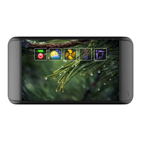
Page 9: Default View
RBC-MTSC1 Mini Touch Screen Controller Installation & Owners Manual 6.3. Default View Pressing the power icon displays the default screen 6.4. Configuration To access Configuration menu follow the sequence below on the screen using two fingers Press and hold the bottom right hand corner of the screen keeping your finger in place (do not remove) and... -
Page 10: Configuration Menu Icons
RBC-MTSC1 Mini Touch Screen Controller Installation & Owners Manual 6.4.1. Configuration Menu Icons General R/C setup User interface setup DN code editing Appearance Occupancy strategy Not assigned or used Diagnostics Model information Reboot button Back button 6.4.2. General R/C Setup... -
Page 11: User Interface Setup
RBC-MTSC1 Mini Touch Screen Controller Installation & Owners Manual 6.4.3. User interface setup Enable or disable: operating mode; temperature change; fan speed; louvre operation. Tap button to change setting. 6.4.4. DN code editing To change DN code settings use up/down arrow to move between DN codes. - Page 12 RBC-MTSC1 Mini Touch Screen Controller Installation & Owners Manual “Reboot button” is visible when configuration setting has changed and requires the indoor unit to be restarted to accept the command. To save settings press “Reboot button” displayed on “Configuration” screen...
-
Page 13: Appearance
RBC-MTSC1 Mini Touch Screen Controller Installation & Owners Manual 6.4.5. Appearance Colour tones can be adjusted to change appearance. Touch paint board to reveal RGB colour sliders. 6.4.6. Occupancy Strategy Enable or disable: temperature setting limits for cooling and heating. Tap button to change setting. - Page 14 RBC-MTSC1 Mini Touch Screen Controller Installation & Owners Manual Enable or disable on/off button. Enable or disable to fix mode. Enable or disable temperature change. To change setpoint use up/down arrow to change value.
- Page 15 RBC-MTSC1 Mini Touch Screen Controller Installation & Owners Manual Enable or disable to fix fan speed. Enable or disable louvre operation. Tap to select fixed louvre position or set auto-swing.
- Page 16 RBC-MTSC1 Mini Touch Screen Controller Installation & Owners Manual Enable or disable temperature setting Enable or disable activity mode settings. Disable prevents selection of activity mode Low fan speed Cooling mode Auto mode Medium fan Temperature Heating mode speed setting...
-
Page 17: Diagnostics
RBC-MTSC1 Mini Touch Screen Controller Installation & Owners Manual 6.4.7. Diagnostics Warning symbol on display indicates fault code. To access diagnostics refer to 6.4 Configuration page 9. Displays error message. Tap air conditioner to reveal error codes. -
Page 18: Model Information
RBC-MTSC1 Mini Touch Screen Controller Installation & Owners Manual 6.4.8. Model information 6.4.9. Reboot button Tap to save and update settings 6.4.10. Back button Tap to exit and return to previous screen 6.5. Version History and New Features Guide 6.5.1. -
Page 19: Trouble Shooting Error Codes
RBC-MTSC1 Mini Touch Screen Controller Installation & Owners Manual Trouble Shooting Error Codes Error Code Description Sending error in TCC-LINK central control device Receiving error in TCC-LINK central control device Batch alarm of general-purpose equipment control interface Communication error between indoor and remote controller (Detected at remote controller side) - Page 20 Comp position detection circuit error Follower indoor unit error (Group error) Note: For further information regarding the above error codes, please contact your local Toshiba A/C supplier, or Toshiba A/C technical support. Note: Toshiba Carrier UK Limited reserves the right to change specification without notice.
- Page 21 RBC-MTSC1 Mini Touch Screen Controller Installation & Owners Manual...
- Page 22 Manchester Leatherhead Plymouth Office Locations Leatherhead Manchester Plymouth Toshiba Air Conditioning Toshiba Air Conditioning Toshiba Carrier UK Limited United Technologies House Unit 15 S:Park Business Park Porsham Close Guildford Road Hamilton Road Belliver Industrial Estate Leatherhead Stockport Plymouth Surrey Greater Manchester...