Advertisement
Quick Links
T
ECHNICAL INFORMATION
Models No.
Description
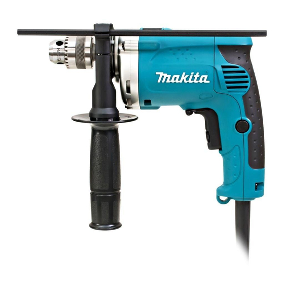
C
ONCEPT AND MAIN APPLICATIONS
Model HP1230 has been developed as a compact and lightweight
12mm (15/32") hammer drill with new exterior design.
This product is also available with plastic carrying case
as Model HP1230K.
S
pecification
Voltage (V)
110
120
220
230
240
No load speed: min
Impacts per min.: min
Drill chuck type
Chuck capacity: mm (")
Capacities: mm (")
Reversing switch
Protection against electric shock
Power supply cord: m (ft)
Net weight: kg (lbs)
S
tandard equipment
Chuck key S-10 ........................ 1
Depth gauge .............................. 1
Side grip .................................... 1
Plastic carrying case ................. 1 (HP1230K only)
Note: The standard equipment for the tool shown above may differ by country.
O
ptional accessories
Various TCT drill bits 3.0 -12mm (1/8 -15/32")
Various HSS metal drill bits 1.5 -6mm (1/16 -1/4")
Phillips bit
Slotted bit
(+) (-) Driver bit
Wool bonnet 100
Rubber pad ass'y
Foam polishing pad 125
Drill stand Type 43
HP1230
Hammer Drill 12 mm (15/32")
Current (A)
Cycle (Hz)
3.8
50/60
3.5
50/60
50/60
1.9
50/60
1.9
50/60
1.8
= rpm
-1
= ipm
-1
Concrete
Steel
Wood
Continuous Rating (W)
Input
400
---
400
400
400
0 - 2,900
0 - 31,900
Keyed chuck
1.5 - 10
(1/16 - 3/8)
12 (15/32)
10 (3/8)
15 (9/16)
Yes
Double insulation
2.0 (6.6)
1.4 (3.1)
PRODUCT
L
W
Dimensions: mm (")
Length (L)
239 (9-3/8)
Width (W)
67 (2-5/8)
Height (H)
188 (7-3/8)
Max. Output (W)
Output
230
300
230
300
230
300
230
300
230
300
P 1/ 8
H
Advertisement

Related Manuals for Makita HP1230


Summary of Contents for Makita HP1230
- Page 1 Description Hammer Drill 12 mm (15/32") ONCEPT AND MAIN APPLICATIONS Model HP1230 has been developed as a compact and lightweight 12mm (15/32") hammer drill with new exterior design. This product is also available with plastic carrying case as Model HP1230K.
-
Page 2: Necessary Repairing Tools
Mounting Ball bearing 6002LLB 1R284 Round bar for arbor 10-50 Removing Spindle [2] LUBRICATION Apply Makita grease N. No.1 to the following portions designated with the black triangle to protect parts and product from unusual abrasion. Item No. Description Portion to lubricate... - Page 3 P 3 / 8 epair [3] DISASSEMBLY/ASSEMBLY [3] -1. Drill Chuck, Spindle, Helical Gear 37, Ball Bearing 6002DDW DISASSEMBLY 1) Hold 1R139 with vise. Fit the flat portion of Spindle to 1R139. (Fig. 2) 2) Hold 1R228 with Drill chuck. Turn Drill chuck counterclockwise with 1R228, 134873-0, 1R224 and 1R223. (Fig.
- Page 4 P 4 / 8 epair [3] DISASSEMBLY/ASSEMBLY [3] -1. Drill Chuck, Spindle, Helical Gear 37, Ball Bearing 6002DDW (Cont.) DISASSEMBLY 1) Turn and remove Conical compression spring 15-24 when it remains at the hole of Gear housing. (Fig. 6) 2) Remove Retaining ring R-32 with 1R005. (Fig. 7) Ball bearing 6002DDW and Cup washer 15.
- Page 5 P 5 / 8 epair [3] DISASSEMBLY/ASSEMBLY [3] -1. Drill Chuck, Spindle, Helical Gear 37, Ball Bearing 6002DDW (Cont.) Fig. 15 ASSEMBLY Spindle must return as soon as you push it down. 7) Assemble the Gear housing to Motor housing. Refer to Fig. 4. Note: Make sure that Conical compression spring works properly as illustrated in Fig.
- Page 6 P 6 / 8 epair [3] DISASSEMBLY/ASSEMBLY [3] -3. Armature DISASSEMBLY 1) Separate Handle cover from Motor housing by unscrewing three binds 4x20 Tapping screws. And disconnect Carbon brush from Armature's Commutator. (Fig. 19) 2) Remove Gear housing and Cam housing from Motor housing by unscrewing three 4x25 tapping screws. Armature comes out together with Cam housing as illustrated in Fig.
-
Page 7: Circuit Diagram
P 7 / 8 ircuit diagram Fig. D-1 Color index of lead wires' sheath Circuit without Choke Coil Black White Poke-in Poke-in Terminal FB Orange Terminal FA of Field of Field Blue Brush holder B Brush holder A Fig. D-1A Circuit with Choke Coil If Choke coil is used instead of Connecting Lead wire (red),... - Page 8 P 8 / 8 iring diagram Fig. D-2 Wiring without Choke Coil Put the slack of the connecting lead wire (blue) of Brush holder in the illustrated position. Fix the Lead wires with Lead wire holder. Brush holder B Brush holder A In case of soldering of Lead wires to the reversing circuit, inflect the Lead wires at the soldered portion...