Siemens SIMATIC ET 200eco PN M12-L Equipment Manual
I/o device digital outputs dq 8x24vdc/0.5a m12-l 8xm12
Hide thumbs
Also See for SIMATIC ET 200eco PN M12-L:
- Operating instructions manual (278 pages) ,
- Compact operating instructions (156 pages) ,
- System manual (127 pages)
Table of Contents
Advertisement
Quick Links
Advertisement
Table of Contents

Related Manuals for Siemens SIMATIC ET 200eco PN M12-L


Summary of Contents for Siemens SIMATIC ET 200eco PN M12-L
- Page 2 Preface ET 200eco PN M12-L Documentation Guide SIMATIC Product overview Wiring ET 200eco PN I/O device digital outputs DQ 8x24VDC/0.5A M12-L 8xM12 Parameters/address space (6ES7142-6BG00-0BB0) Interrupts/diagnostics alarms Equipment Manual Technical specifications Dimension drawing 07/2020 A5E46570894-AA...
- Page 3 Note the following: WARNING Siemens products may only be used for the applications described in the catalog and in the relevant technical documentation. If products and components from other manufacturers are used, these must be recommended or approved by Siemens. Proper transport, storage, installation, assembly, commissioning, operation and maintenance are required to ensure that the products operate safely and without any problems.
-
Page 4: Preface
Siemens' products and solutions undergo continuous development to make them more secure. Siemens strongly recommends that product updates are applied as soon as they are available and that the latest product versions are used. Use of product versions that are no longer supported, and failure to apply the latest updates may increase customers' exposure to cyber threats. -
Page 5: Table Of Contents
Table of contents Preface ..............................3 ET 200eco PN M12-L Documentation Guide ..................5 Product overview ........................... 9 Properties ..........................9 Operator controls and display elements ................11 Wiring ..............................12 Terminal and block diagram ....................12 Pin assignment ........................14 Parameters/address space ........................ -
Page 6: Et 200Eco Pn M12-L Documentation Guide
This arrangement enables you to access the specific content you require. Basic information The system manual describes in detail the configuration, installation, wiring and commissioning of the SIMATIC ET 200eco PN M12-L distributed I/O system. The STEP 7 online help supports you in the configuration and programming. Device information... - Page 7 You must register once to use the full functionality of "mySupport". You can find "mySupport" on the Internet (https://support.industry.siemens.com/My/ww/en). Application examples The application examples support you with various tools and examples for solving your automation tasks.
- Page 8 You can find the SIMATIC Automation Tool on the Internet (https://support.industry.siemens.com/cs/ww/en/view/98161300). PRONETA SIEMENS PRONETA (PROFINET network analysis) allows you to analyze the plant network during commissioning. PRONETA features two core functions: • The topology overview automatically scans the PROFINET and all connected components.
- Page 9 ET 200eco PN M12-L Documentation Guide SINETPLAN SINETPLAN, the Siemens Network Planner, supports you in planning automation systems and networks based on PROFINET. The tool facilitates professional and predictive dimensioning of your PROFINET installation as early as in the planning stage. In addition, SINETPLAN supports you during network optimization and helps you to exploit network resources optimally and to plan reserves.
-
Page 10: Product Overview
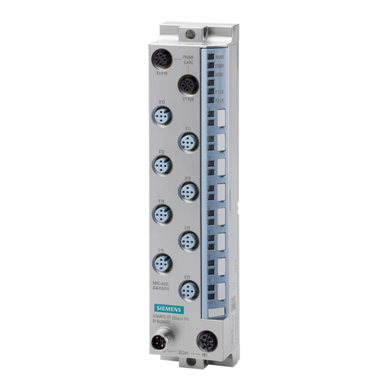
Product overview Properties Article number 6ES7142-6BG00-0BB0 View of the I/O device Figure 2-1 View of the I/O device DQ 8x24VDC/0.5A M12-L 8xM12 I/O device digital outputs DQ 8x24VDC/0.5A M12-L 8xM12 (6ES7142-6BG00-0BB0) Equipment Manual, 07/2020, A5E46570894-AA... - Page 11 Product overview 2.1 Properties Properties The I/O device has the following technical properties: • 8 digital outputs • M12 sockets for connection of actuators • Rated supply voltage 24 V DC • Rated load voltage 24 V DC • Integrated switch with 2 ports •...
-
Page 12: Operator Controls And Display Elements
Product overview 2.2 Operator controls and display elements Operator controls and display elements The figure below shows the operator controls and display elements of the DQ 8x24VDC/0.5A M12-L 8xM12 I/O device. ① PN/MF (LAN): Sockets for connecting PROFINET ② RN/NS: RUN/network status LED ③... -
Page 13: Wiring
Wiring Terminal and block diagram The figure below shows an example of the pin assignment of signal outputs with single and dual assignment of the sockets. I/O device digital outputs DQ 8x24VDC/0.5A M12-L 8xM12 (6ES7142-6BG00-0BB0) Equipment Manual, 07/2020, A5E46570894-AA... - Page 14 Wiring 3.1 Terminal and block diagram ① Bus interface with integrated 2-port switch Supply voltage 1L+ (non-switched) ② Monitoring Ground 1M (non-switched) ③ DQ circuit Load voltage 2L+ (switched) ④ Internal supply voltage Ground 2M (switched) ⑤ Output (dual assignment of the socket) Output signal ⑥...
-
Page 15: Pin Assignment
Wiring 3.2 Pin assignment Pin assignment Terminal assignment PROFINET connector The following table shows the pin assignment of the PROFINET connector. Table 3- 1 Pin assignment of the PROFINET connector, port 1 and 2 Assignment of the core Assignment Front view of the connectors color of the PROFINET cable Assignment X1 P1R... - Page 16 Wiring 3.2 Pin assignment Pin assignment of sockets for digital outputs The table below shows the pin assignment of the 8 sockets for the connection of the digital outputs. Table 3- 2 Pin assignment for digital outputs Assignment Front view of the sockets X10 to X17 - sockets for digital outputs X10, X12, X11, X13,...
- Page 17 Wiring 3.2 Pin assignment The following graphic shows the assignment of the output signals to the respective sockets with dual or single assignment. Figure 3-2 Assignment of output signals with dual or single assignment of sockets Pin assignment of the connector for infeed of the supply voltage (M12 L-coded) The table below shows the pin assignment of the M12 L-coded connector for infeed of the supply voltage.
- Page 18 Wiring 3.2 Pin assignment Pin assignment of the socket for loop-through of the supply voltage (M12 L-coded) The table below shows the pin assignment of the M12 L-coded socket for loop-through of the supply voltage. Table 3- 4 Pin assignment of the supply voltage socket Assignment of the Assignment Front view of the...
-
Page 19: Parameters/Address Space
Parameters/address space Parameters The table below shows the parameters for the I/O device DQ 8x24VDC/0.5A M12-L 8xM12. Table 4- 1 Configurable parameters and their defaults (GSD file) Parameters Value range Default Scope with configu- ration software, e.g. STEP 7 (TIA Portal) Diagnostics: Undervoltage 1L+ Disable Channel... -
Page 20: Explanation Of The Parameters
Parameters/address space 4.2 Explanation of the parameters Explanation of the parameters Diagnostics: Undervoltage 1L+ Enabling of diagnostics for insufficient supply voltage 1L+. Diagnostics: Undervoltage 1L+ triggers the "Undervoltage" maintenance event. You can find more information in section Maintenance events (Page 29). Diagnostics: Missing 2L+ Enabling of the diagnostics for missing or insufficient load voltage 2L+. -
Page 21: Address Space
Parameters/address space 4.3 Address space Address space The DQ 8x24VDC/0.5A M12-L 8xM12 I/O device can be configured differently; see following table. Depending on the configuration, additional/different addresses are assigned in the process images. Configuration options of the DQ 8x24VDC/0.5A M12-L 8xM12 I/O device You can configure the I/O device digital outputs with STEP 7 (TIA Portal) or with a GSD file. - Page 22 Parameters/address space 4.3 Address space Value status (Quality Information, QI) The value status is always returned with the following configuration options: • DQ 8x24VDC QI, • DQ 8x24VDC MSO Evaluating the value status An additional byte is occupied in the input address space if you enable the value status for the I/O device.
- Page 23 Parameters/address space 4.3 Address space Value status (Quality Information,QI) The meaning of the value status depends on the submodule on which it occurs. For the 1st Submodule (= basic submodule), the value status 0 indicates: The module detects that an error is pending at the channel and that the value is faulty. For the 2nd Submodule (= MSO submodule), the value status 0 indicates: •...
- Page 24 You can find information on the functionality Module-internal Shared Input/Shared Output (MSI/MSO) in the STEP 7 online help or in the function manual SIMATIC PROFINET with STEP 7 (https://support.industry.siemens.com/cs/ww/en/view/49948856). I/O device digital outputs DQ 8x24VDC/0.5A M12-L 8xM12 (6ES7142-6BG00-0BB0) Equipment Manual, 07/2020, A5E46570894-AA...
-
Page 25: Interrupts/Diagnostics Alarms
Interrupts/diagnostics alarms Status and error displays LED displays The figure below shows the LED displays (status and error displays) of the I/O device DQ 8x24VDC/0.5A M12-L 8xM12. ① RN/NS: RUN/network status LED (green) ② ER/MS: ERROR/module status LED (red) ③ MT/IO: MAINT/IO status LED (yellow) ④... - Page 26 Interrupts/diagnostics alarms 5.1 Status and error displays Meaning of the LEDs The following tables set out the meaning of the status and error displays. Measures for dealing with diagnostics alarms can be found in the section Diagnostics alarms (Page 28). Behavior of the LEDs RN/NS (RUN/network status), ER/MS (ERROR/module status) and MT/IO (MAINT/IO status) on PROFINET Table 5- 1...
- Page 27 Interrupts/diagnostics alarms 5.1 Status and error displays LEDs Meaning Solution Maintenance Evaluate the maintenance events. rele- rele- vant vant The "Node flash test" is running (the P1 LK and P2 LK LEDs of the PROFINET Flash- Flash- Flash- interface are also flashing). Hardware or firmware defective.
-
Page 28: Interrupts
Interrupts/diagnostics alarms 5.2 Interrupts Channel status/channel error LEDs Table 5- 4 Status and error display of the channel status/channel error LEDs LEDs Meaning Channel sta- tus/channel error Process value = 0 Process value = 1 Channel diagnostics Interrupts The I/O device digital outputs DQ 8x24VDC/0.5A M12-L 8xM12 supports diagnostic interrupts and maintenance alarms. -
Page 29: Alarms
Interrupts/diagnostics alarms 5.3 Alarms Alarms 5.3.1 Diagnostics alarms A diagnostics alarm is output for each diagnostics event. On the I/O device DQ 8x24VDC/0.5A M12-L 8xM12 the LED ER/MS flashes red. You can read out the diagnostics alarms in the diagnostics buffer of the CPU, for example. You can evaluate the error codes with the user program. -
Page 30: Maintenance Events
Interrupts/diagnostics alarms 5.3 Alarms 5.3.2 Maintenance events Triggering of a maintenance event The PROFINET interfaces of the ET 200eco PN M12-L support the diagnostic concept and maintenance concept in PROFINET according to the IEC 61158-6-10 standard. The goal is to detect and remove potential problems as soon as possible. -
Page 31: Technical Specifications
Technical specifications of the I/O device DQ 8x24VDC/0.5A M12-L 8xM12 The following table shows the technical specifications as of 07/2020. You can find a data sheet including daily updated technical specifications on the Internet (https://support.industry.siemens.com/cs/de/en/pv/6ES7142-6BG00-0BB0/td?dl=en). Article number 6ES7142-6BG00-0BB0 General information... - Page 32 Technical specifications Article number 6ES7142-6BG00-0BB0 Input current Current consumption (rated value) 65 mA; without load from load voltage 1L+ (unswitched voltage) 12 A; Maximum value from load voltage 2L+, max. 12 A; Maximum value Power loss Power loss, typ. Address area Address space per module 1 byte for QI information •...
- Page 33 Technical specifications Article number 6ES7142-6BG00-0BB0 Switching frequency 100 Hz • with resistive load, max. 0.5 Hz • with inductive load, max. 1 Hz • on lamp load, max. Total current of the outputs • Current per module, max. Cable length 30 m •...
- Page 34 Technical specifications Article number 6ES7142-6BG00-0BB0 Open IE communication • TCP/IP • SNMP • LLDP Isochronous mode Equidistance shortest clock pulse 250 µs max. cycle 4 ms Jitter, max. 10 µs Interrupts/diagnostics/status information Substitute values connectable Alarms Yes; Parameterizable • Diagnostic alarm Yes;...
- Page 35 Technical specifications Article number 6ES7142-6BG00-0BB0 Degree and class of protection IP degree of protection IP65/67 Ambient conditions Ambient temperature during operation -40 °C • min. 60 °C • max. Altitude during operation relating to sea level Up to max. 5 000 m, at installation height > 2 000 •...
-
Page 36: Dimension Drawing
Dimension drawing Dimension drawing The figure below shows the dimension drawing of the I/O device digital outputs DQ 8x24VDC/0.5A M12-L 8xM12 in front and side views. Figure A-1 Dimension drawing I/O device digital outputs DQ 8x24VDC/0.5A M12-L 8xM12 (6ES7142-6BG00-0BB0) Equipment Manual, 07/2020, A5E46570894-AA...