Advertisement
Quick Links
s
Installation Sheet
January, 2016
Supersedes February, 2013
Description
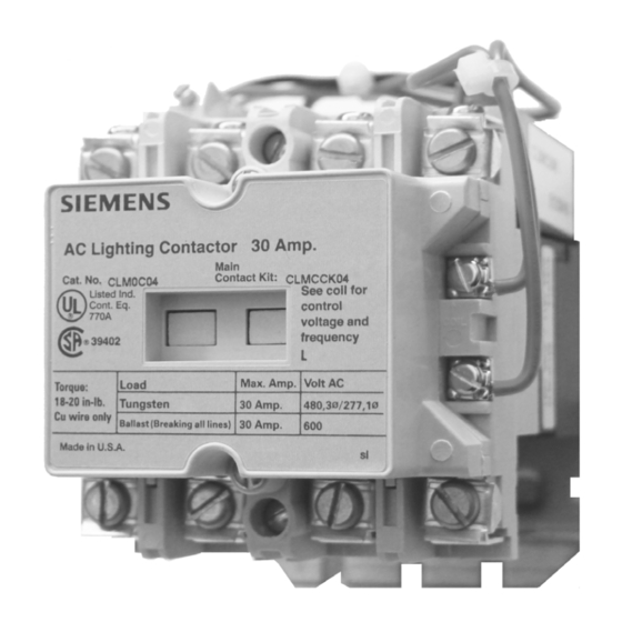
Magnetically latched CLM lighting and heating contactors can
control tungsten, fluorescent and metal vapor lamp or heating
loads. (Table 1 below shows the voltage and current rating for
various loads). Each contactor and its associated load should be
protected against short circuits by a suitable branch circuit pro-
tective device selected in accordance with the National Electric
Code (NEC).
Table 1 – Contactor Ratings
Catalog Number
Cont. Current Rating, Amp.
Tungsten
Max. Volts, line-line
Max. Volts, line-Neutral
Ballast
Max. Volts, line-line
Max. Volts, line-Neutral
Heating
Max. Volts, line-line
Max. Volts, line-Neutral
AC Coil Data
Poles
2-4
5.
Auxiliary Contact Ratings (A600, R300)
Voltage
Continuous
120-600 VAC
10A
72-120 VAC
10A
28-72 VAC
10A
28-300 VDC
1A
Theory of Operation
Each contactor contains a permanent magnet built into its struc-
ture that will maintain the contactor in its energized state indefi-
nitely without using control power. When energized, DC voltage
is applied to produce a magnetic field that reinforces the polarity
of the permanent magnet and the contactor closes. Immediately,
the current to the coil is disconnected by the coil clearing aux-
iliary contact. In order to open the contactor, it is necessary to
create a field through the OFF coil in the reverse direction to the
permanent magnet. This momentarily cancels the magnetic at-
traction and the contactor drops out.
Siemens Industry, Inc. 5300 Triangle Parkway, Norcross, GA 30092
Contactor Rating
CLM0C
30
480
277
600
346
600
346
Inrush VA
Dropout VA
410
410
Make
Break
7200VA
720VA
60A
720VA
60A
28VA
Each CLM contactor has an electronic control module
"CLMKCMR" which is used to energize and close the
contactor and for the release circuit. It is designed for short
time actuation of 1-3 cycles only. All coils are designed with
a small wattage resistor in addition to a diode at coil voltages
higher than 120 volts. Remote solid state switching devices
40
have 'off state' leakage currents. They may also pass utility
40
transient voltages through to the device electronics. The low
level 'off state' voltages are insufficient to actuate the contactor
but large enough to burn out the resistors. Normal actuating
voltages are quickly disconnected from the coils and control
module by the latch clearing contacts. Coil and module
failures are possible when used with solid state relays and
PLC outputs. 24-volt systems are ok to use, but 120 volts
10A
and above should be discouraged. If higher voltages cannot
28VA
be avoided, an interposing relay should be used.
Care should be taken when servicing that leads do not be-
come changed from their factory installed terminals, or im-
proper operation and possibly permanent damage to the
contactor could result.
CAUTION: Do not apply AC voltage directly to the coil
terminals of this device! The permanent magnet will be
demagnetized and the rectifier will be damaged if alter-
nating current or wrong polarity direct current is ap-
plied directly to the coil.
E87010-A0104-T003-A6-CLM0
Lighting and Heating Contactor
30 Amp 2, 3, 4, 5 Pole
Magnetically Latched
A5E31166447A-002
Advertisement

Related Manuals for Siemens E87010-A0104-T003-A6-CLM0


Summary of Contents for Siemens E87010-A0104-T003-A6-CLM0
- Page 1 OFF coil in the reverse direction to the nating current or wrong polarity direct current is ap- permanent magnet. This momentarily cancels the magnetic at- traction and the contactor drops out. plied directly to the coil. A5E31166447A-002 Siemens Industry, Inc. 5300 Triangle Parkway, Norcross, GA 30092...
- Page 2 Replacement of both is recommended when the contactor will not pull in or drop out. Coil replacement for the purpose of changing the control voltage rating does not require auxiliary contact or control module replacement.) Siemens Industry, Inc. 5300 Triangle Parkway, Norcross, GA 30092 A5E31166447A-002...
-
Page 3: Auxiliary Contact
Wiring made to any other terminal points will burn out the coil and diode. If a coil burnout occurs, both the coil and the diode must be replaced. Siemens Industry, Inc. 5300 Triangle Parkway, Norcross, GA 30092 A5E31166447A-002... - Page 4 CLMFCCK11 WHITE WHITE ( - ) ( - ) CLMFCAK11 Fig. 3 Connection for 2 Wire Control Fig. 4 Connection for Hand/Off/Auto Control Fig. 5 Dimension Drawing 30 Amp Device Siemens Industry, Inc. 5300 Triangle Parkway, Norcross, GA 30092 A5E31166447A-002...
-
Page 5: Short Circuit Ratings
A small amount of heat will stop corrosion that occurs from moisture due to condensation. Siemens Industry, Inc. 5300 Triangle Parkway, Norcross, GA 30092 A5E31166447A-002... -
Page 6: Troubleshooting
Wrong Coil or Check coil marking and wiring. Wrong Connection should be referred to the local SIemens Industry, Inc., Sales Office. Mechanical Obstruction With power off, check for movement of armature and contacts.