
Related Manuals for ABB GSC Series


Summary of Contents for ABB GSC Series
- Page 1 1ZSC000563-AAX EN, REV. A, 2019-03-21 Transformer bushing, type GSC Installation and maintenance guide...
- Page 2 The information contained in this document may be subject to change without prior warning and should not be considered as binding on ABB AB’s behalf. ABB AB accepts no liability for any errors that may appear in this document. ABB AB is not liable for any damage resulting from the incorrect interpretation of this document.
-
Page 3: Table Of Contents
Contents Safety Levels of safety risks ................................... 5 Hazardous working situations ..............................6 Safety precautions..................................6 Product description Design ......................................7 Technical specifications ................................11 2.2.1 General specifications ............................... 11 2.2.2 Mechanical loading..............................11 Delivery Incoming inspection..................................13 Transportation ..................................... - Page 4 Spare parts Summary ..................................... 51 Disposal and environmental information Overview ..................................... 53 Disposal and recycling ................................53 References 10.1 Summary ..................................... 55 Installation and maintenance guide 1ZSC000563-AAX EN, REV. A, 2019-03-21...
-
Page 5: Safety
1 Safety 1.1 Levels of safety risks Throughout the manual, various types of safety risks are indicated. The most serious level on this scale provides a warning about serious personal injury or possible death, or major damage to a product, if the instructions are not observed. -
Page 6: Hazardous Working Situations
1.2 Hazardous working situations Hazard Action Working close to high voltage. Disconnect all plant power. Ground all objects at the workplace. If work must be done close to live plant components, make sure that the safety distance is in compliance with the applicable safety regulations. -
Page 7: Product Description
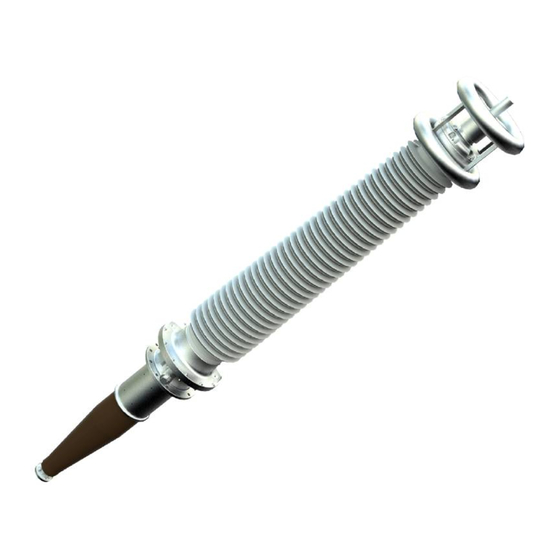
2 Product description 2.1 Design Overview The GSC type is a transformer bushing. It is made for immersed oil to air service. The bushing is of the dry, gas-free type, with a resin impregnated paper RIP condenser core as the primary insulation, and silicone rubber (SiR) sheds as outdoor insulation. - Page 8 General schematics There can be some variation depending on type and configuration. Outer terminal Composite insulator (SiR) Mounting flange RIP condenser core Test tap/voltage tap Ground shield Installation and maintenance guide 1ZSC000563-AAX EN, REV. A, 2019-03-21...
- Page 9 Test tap The bushing has a test tap that is connected to the outermost conductive layer of the condenser core. The test tap is used to measure the bushing insulation by capacitance and dissipation factor. The cover connects the outermost conductive layer to ground, and must always be installed when the bushing is energized. The maximum one minute test voltage for this test tap is 2 kV .
- Page 10 Voltage tap The voltage tap is available as an option, instead of the test tap. The bushing has a voltage tap that is connected to the second outermost conductive layer of the condenser core. The voltage tap is used to measure the bushing insulation by capacitance and dissipation factor. The cover connects the outermost conductive layer to ground, and must always be installed when the bushing is energized.
-
Page 11: Technical Specifications
In the axial direction (3), the bushing can withstand a static load of 20 kN. NOTE! The loads described in this section are static loads, for dynamic loads such as earthquakes and extreme wheather conditions, please contact your ABB sales representative. Installation and maintenance guide 1ZSC000563-AAX EN, REV. A, 2019-03-21... - Page 12 Maximum cantilever load, vertical (0°) Maximum cantilever load, horizontal (90°) Maximum axial static load Load applied at the midpoint Type Maximum cantilever load in operation at Maximum cantilever installation angle (N) test load (N) 0° 90° GSC 200 3200 2000 6300 GSC 300...
-
Page 13: Delivery
3 Delivery 3.1 Incoming inspection • Make sure that all items have been delivered, refer to the packing list. • Carefully inspect the bushings for shipping damage. NOTE! The bushing has been routine tested in oil, and there can be small quantities of oil remaining on the oil-side of the bushing. -
Page 14: Lifting
3.4 Lifting 3.4.1 Lifting the transport box Overview Center of gravity Soft lifting slings Forklift lifting points Procedure Make sure that the crane and the soft lifting slings are approved for the total weight of the transport box and bushing. Refer to the weight in the packing list. Attach soft lifting slings (2) to the designated locations. -
Page 15: Lifting The Bushing Out Of The Transport Box
3.4.2 Lifting the bushing out of the transport box Overview Procedure Make sure that the crane is approved for lifting the weight of the bushing. Refer to the weight on the rating plate. Open the transport box. NOTE! The cover is attached with bolts. Remove the support blocks from the transport box and put them on the ground. - Page 16 Attach a soft lifting sling to the outer terminal and then to the crane hook. CAUTION! Attach the soft lifting sling as close to the top housing as possible, or damage will occur. Carefully lift the bushing. Lower the bushing onto the support blocks. NOTE! If there are no support blocks then use soft bedding.
-
Page 17: Installation
4 Installation 4.1 Tools Tool Part number Note Lifting tool 9760 667-A GSC 200/300/300E/400 1ZSC004867-AAA GSC 450S/450E/500/500E Soft bedding E.g. rubber mat or wood board Soft lifting slings Pull-through cord 9760 669-A With M8 terminal. Torque wrench key for hex socket screws, 16 mm (M10) and 13 mm (M8), torque 20 to 40 Nm. -
Page 18: Removing Transport Container And Outer Terminal
4.3.2 Removing transport container and outer terminal Procedure for removing transport container and outer terminal Make sure that the crane can lift the bushing. Refer to net weight in the packing list. Attach soft lifting slings arround the transport container to the crane hook. Remove the transport container. -
Page 19: Lifting Type Gsc 200/300/300E/400
4.3.3 Lifting type GSC 200/300/300E/400 Overview When lifting the bushing GSC 200/300/300E/400 for installation at vertical angle, arrange the lifting according to position (6) in the figure. When lifting the bushing for installation at a specific angle, use a shackle and arrange according to position (5) in the figure. - Page 20 Procedure for lifting type GSC 200/300/300E/400 Install the lifting tool (1) with the bolts (8) and the washers (9). NOTE! For the GSC 200/300/300E/400 the 9760 667-A lifting tool is used. NOTE! Align the lifting tool with the lifting eyes on the flange.
-
Page 21: Lifting Type Gsc 450S/450E/500/500E
Carefully lift the bushing. CAUTION! Make sure that the bushing does not rotate. NOTE! Place a soft bedding under the condenser core bottom. Adjust the shackle (4) until the bushing flange has the same angle as the tranformer flange. End of instruction 4.3.4 Lifting type GSC 450S/450E/500/500E Overview When lifting the bushing GSC 450S/450E/500/500E for installation at vertical angle, arrange the lifting... - Page 22 Procedure for lifting type GSC 450S/450E/500/500E Install the lifting tool (1) with the bolts (8) and the washers (9). NOTE! For the GSC 450S/450E/500/500E the 1ZSC004867-AAA lifting tool is used. NOTE! Align the lifting tool with the lifting eyes on the flange. Torque 40 ±4 Nm For vertical installation: attach soft lifting slings...
-
Page 23: Installation With Draw Rod At The Transformer Factory
4.4 Installation with draw rod at the transformer factory Overview The draw rod is usually installed in the bushing when it is delivered from ABB, the first step at the transformer factory is therefore to remove it. Upper draw rod... - Page 24 Procedure Apply Vaseline to the screw thread on the pull-through cord (12), then connect it to the draw rod. NOTE! Or use a lubricant with equal properties to Vaseline. Remove the M16 nut (10) on the draw rod. Pull down the draw rod from the bottom end of the bushing, and disassemble it at the lower joint (8).
- Page 25 Remove the transformer cover (13) from the transformer (11). Install the winding cables to the bottom contact. CAUTION! Make sure that there is no tension in the windig cables. Tension in the winding cables will cause damage to the bottom contact. Torque 68 ±6 Nm Only for the GSC 200/300/400/450S.
- Page 26 Connect the draw rod (1) to the lower draw rod (4). Hold the pull-through cord (12) in tension, while lowering the bushing onto the transformer. NOTE! Put plastic sleeves on two or three of the stud bolts, to guide the flange and to prevent damage to the stud bolts.
- Page 27 Install the washer and nut on the draw rod. NOTE! Apply a generous amount of Molykote Multilub on the nut, washer and drawrod bolt. Remove any excess Molykote Multilub with a rag. Remove the lifting gear and the pull-though cord. Tighten the nut.
- Page 28 Turn the nut clockwise according to the value in the table. Distance (b) = (a) + table value. CAUTION! Continuously measure the torque when turning the nut. If the maximum torque is reached before the target distance then remove the nut and draw rod bolt to apply more Molykote Multilub and tighten again.
-
Page 29: Installation With Draw Rod At Site
4.5 Installation with draw rod at site Upper draw rod Flexible pull-through cord Lower draw rod with bottom contact Bottom contact Bushing Procedure NOTE! This procedure is only valid if the lower draw rod with bottom contact (5) is already installed in the transformer. - Page 30 Remove the M16 nut (10). Carefully clean the bottom end of the bushing, and the inside of the center hole. Look for damage. Pull down the uper draw rod (1) from the bottom end of the bushing. Remove the transport cover (13) from the transformer (11) and the lower draw rod (4).
- Page 31 Apply locking fluid on the threads (8) on the lower draw rod (4). NOTE! Use thread-locking fluid 1269 0014-408. Connect the upper draw rod (1) to the lower draw rod (4). Hold the pull-through cord (12) in tension, while lowering the bushing onto the transformer. NOTE! Put plastic sleeves on two or three of the stud bolts to guide the flange and...
- Page 32 Install the nuts and washers. Tighten the nuts in a crosswise sequence. Torque Please refer to the transformer documentation. Install the washer and nut on the draw rod. NOTE! Apply a generous amount of Molykote Multilub on the nut, washer and drawrod bolt.
- Page 33 Measure the distance (a). NOTE! The bushing is delivered with an information sheet that specifies the measurement (b-a) and torque of the draw rod nut. These values are measured when the bushing is manufactured, and are unique to every unit. Turn the nut clockwise according to the value in the table.
-
Page 34: Installation Of The Outer Terminal
If using a hydraulic jack: Pull the draw rod with a force according to the table. Tighten the nut on the draw rod with your hand. Remove the hydraulic jack. Type Force with CT extension 600 mm GSC 200 37 kN GSC 300 36.3 kN GSC 300E... - Page 35 Assemble the tightening ring (4), the O-ring (3), and the outer terminal (5). Apply Molykote Multilub to the washers, and to the threads and the shank of the M10 bolts (2). NOTE! Or use a lubricant with equal properties to Molykote Multilub. Install the M10 bolts (2) and plain washers.
- Page 36 Install the M8 bolts (1), conical spring-washers and plain washers. Tighten the bolts in a crosswise sequence. CAUTION! Do NOT use an impact driver / wrench! Torque 20 ±2 Nm Install the external connections. Refer to the documentation from the supplier of the external connection.
-
Page 37: Grounding Of The Bushing Flange
4.7 Grounding of the bushing flange Overview The bushing flange must be grounded to the transformer tank. This prevents electrical discharge between the bushing flange and the transformer tank under normal service conditions. There are two alternatives. DANGER! Make sure that the grounding is correct. An unsatisfactory grounding can cause damage to equipment, or death to personnel. - Page 38 Procedure with a flexible cable Put a flexible cable (14) between the grounding hole in the bushing flange and a grounding point on the transformer. Apply a large quantity of Mobilgrease 28 to the bolt (13). CAUTION! The quality of the bolt is important, stainless steel of A4-80 quality is recommended. NOTE! Or use a lubricant similar to Mobilgrease 28.
-
Page 39: Flashover Distance
4.8 Flashover distance The distance to external objects from the top of the bushing is very important for the safe operation of the bushing. A clear area around the high voltage end of the bushing must be maintained, to prevent flashover or other disturbances. - Page 40 Installation and maintenance guide 1ZSC000563-AAX EN, REV. A, 2019-03-21...
-
Page 41: Commissioning
5 Commissioning 5.1 Waiting time before energization Waiting times after oil-filling of the transformer Some waiting time is necessary after the transformer has been oil-filled, before the bushing is energized. The reason for this is that air bubbles stick to the bushings surface when the transformer is filled with oil, and flashovers and partial discharges can form in the bubbles. -
Page 42: Tightness Test Of Bushing Outer Terminal
Water could enter directly into the transformer insulation. It is thus recommended to do a tightness test after installation of the bushing, both with vacuum and pressure. Different methods can be used, and ABB refers to the instructions given by the company responsible for the field erection of the bushing. - Page 43 Nominal capacitance The capacitance (C ) depends on the transformer, and it is not possible to give a nominal value that is valid for all service conditions. Thus, it is important to measure and record the capacitance (C ) for future reference, such as repairs, service etc.
-
Page 44: Measurement Of Through-Resistance
Measure the capacitance (C ) between the outer terminal and the stud (1). NOTE! Refer to the table for the nominal capacitance (C ), Nominal capacitance, page 43. Measure the capacitance (C ) between the stud (1) and the flange. NOTE! Record the capacitance (C ) for future reference. - Page 45 Procedure Record the temperature of the transformer winding. NOTE! The resistance of metals depends on their temperature. Because the transformer winding usually dominates the total resistance, the average winding temperature at the time of measurement must be recorded. Measure the through-resistance from outer terminal to outer terminal. Calculate the measured resistance to the reference temperature.
- Page 46 Installation and maintenance guide 1ZSC000563-AAX EN, REV. A, 2019-03-21...
-
Page 47: Maintenance
Make a visual inspection for oil leakage during regular station supervision. After repairs ABB recommends that the capacitance is measured after repairs have been done, and after service of connected equipment or after work near the bushing is completed. It is important to compare the capacitance before energization with the capacitance that was measured at commisioning. - Page 48 Installation and maintenance guide 1ZSC000563-AAX EN, REV. A, 2019-03-21...
-
Page 49: Re-Packing
7 Re-packing 7.1 Re-packing of the bushing Overview Procedure Install the transport container (1): Replace the drying agent in the transport container (1). Install the gasket (2). Carefully put the transport container on the bushing, and install the bolts. CAUTION! Make sure that the transport container Torque does not cause damage to the... - Page 50 Lower the bushing into the transport box. CAUTION! Make sure that the support blocks are in the correct positions in the transport box. CAUTION! Make sure that the test tap does not make contact with the transport box, or other objects. Attach the bushing to the transport box in the same way as when it was delivered.
-
Page 51: Spare Parts
8 Spare parts 8.1 Summary If the bushing is damaged, we recommend that it is returned to ABB for repairs and re-testing. Some parts that are damaged or lost during transportation or installation, can be ordered from ABB. Installation and maintenance guide... - Page 52 Installation and maintenance guide 1ZSC000563-AAX EN, REV. A, 2019-03-21...
-
Page 53: Disposal And Environmental Information
9.2 Disposal and recycling ABB strives to minimize the product's impact on the environment throughout its entire life cycle. Technical and product development focuses on environmental aspects. The ecocycle approach is striven for, and consideration is taken to the materials' environmental impact and recycling alternatives. - Page 54 Many metal components of iron, steel and aluminum are large and easy to identify, e.g. support structures. ABB strives to reduce the use of precious metals and the release of environmentally hazardous metals.
-
Page 55: References
10 References 10.1 Summary • Markings: Conforming to IEC/IEEE. • Bushing diagnostics and conditioning, 2750 515-142. • Technical guide, 1ZSC000563-AAW. • Test adapter, Installation and maintenance guide, 1ZSC000563-ACD. • Transformer oil, IEC 60296, class 2. • Handling and Cleaning of Composite Insulators, SEPTPT/ PL/T/MB 2193. •... - Page 56 ABB AB, Components SE-771 80 Ludvika, Sweden www.abb.com/transformercomponents © Copyright 2019 ABB, All rights reserved. Specifications subject to change without notice.