Table of Contents
Advertisement
INSTALLATION MANUAL
AIR
CONDITIONER
Please read this installation manual completely before installing the product.
Installation work must be performed in accordance with the national wiring
standards by authorized personnel only.
Please retain this installation manual for future reference after reading it
thoroughly.
Vertical Air Handling Unit
P/NO : MFL65003108
Copyright © 2014 - 2018 LG Electronics Inc. All Rights Reserved.
http://www.lghvac.com
www.lg.com
Advertisement
Table of Contents

Related Manuals for LG MULTI V ARNU363NJA4.AMBBLUS


Summary of Contents for LG MULTI V ARNU363NJA4.AMBBLUS
- Page 1 Installation work must be performed in accordance with the national wiring standards by authorized personnel only. Please retain this installation manual for future reference after reading it thoroughly. Vertical Air Handling Unit http://www.lghvac.com www.lg.com P/NO : MFL65003108 Copyright © 2014 - 2018 LG Electronics Inc. All Rights Reserved.
- Page 2 IMPORTANT! Please read this instruction sheet completely before installing the product. This air conditioning system meets strict safety and operating standards. As the installer or service person, it is an important part of your job to install or service the system so it operates safely and efficiently. WARNING •...
-
Page 3: Table Of Contents
Vertical Air Handling Unit Installation Manual TABLE OF CONTENTS Installation Requirements Required Parts Required Tools Features........4 Duct Connection Dimensions ...5 Safety Precautions ....6 Installation.........9 Selection of the best location..9 Upflow Installation ....10 o Level gauge Duct work........11 o Screw driver Horizontal-left Installation ..12 o Electric drill Preparation of Piping....13... -
Page 4: Features
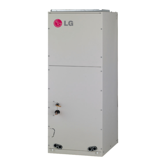
Feature Features Wiring knockouts for conduit Wiring knockouts for conduit Refrigerant connections Drain connections for horizontal application Filter access Drain connections for upflow application 4 Vertical Air Handling Unit... -
Page 5: Duct Connection Dimensions
Feature Duct Connection Dimensions <Top> Refrigerant Drain connections connections for upflow application Drain connections for horizontal application Air filter cover <Front> <Side-right> <Bottom> (Unit: inch(mm)) Wiring Dimensions Refrigerant Knock out Connections Capacity Pipe size (kBtu/h (RT)) Commu Height Width Depth Power Liquid nication... -
Page 6: Safety Precautions
Safety Precautions Safety Precautions To prevent injury to the user or other people and property damage, the following instructions must be followed. n Incorrect operation due to ignoring instruction will cause harm or damage. The seriousness is classi- fied by the following indications. WARNING This symbol indicates the possibility of death or serious injury. - Page 7 Safety Precautions • Use a vacuum pump or Inert (nitrogen) gas when doing leakage test or air purge. Do not compress air or Oxygen and Do not use Flammable gases. Otherwise, it may cause fire or explosion. - There is the risk of death, injury, fire or explosion. Operation •...
- Page 8 Safety Precautions CAUTION Installation • Always check for gas (refrigerant) leakage after installation or repair of product. - Low refrigerant levels may cause failure of product. • Install the drain hose to ensure that water is drained away properly. - A bad connection may cause water leakage. •...
-
Page 9: Installation
Installation Installation Selection of the best location • Where optimum air distribution can be ensured. • Where nothing blocks air passage and install the duct work. • Where condensate can be properly drained. • Where the ceiling is strong enough to bear the indoor unit weight. •... -
Page 10: Upflow Installation
Installation Upflow Installation • Position unit for plenum installation. • The plenum should be secured in order to support the installation of adapter callers accommodate the installation of any duct work. • Seal all duct work according to local codes to prevent air leakage. Ensure that filter access is unob- structed. -
Page 11: Duct Work
Installation Duct work • Over 10 screws should be used for joining supply duct with the unit. • To prevent vibration transmission, exploit flexible connectors between duct and the unit. It is mandato- ry that the flexible connector between unit and duct at discharge connection should be made off heat resistive material when electric heater is installed. -
Page 12: Horizontal-Left Installation
Installation Horizontal-left Installation • It is particular that the units should not be installed in such a manner that the access panels facing up or down • It should be confirmed that the installation is in accordance with all relevant building codes that may necessitate installation of external condensate pan. -
Page 13: Preparation Of Piping
Installation Preparation of Piping Cut the pipes 1. Use the pipes purchased locally. 2. Measure the distance between the indoor and the outdoor unit. 3. Cut the pipes a little longer than measured distance. Copper pipe Slanted Uneven Rough 90° Burrs removal 1. - Page 14 Installation Cutting the Pipe for Cutting the Pipe for Cutting the Pipe for Cutting the Pipe for 3/8inch (9.52mm). 3/8inch (9.52mm). 3/8inch (9.52mm). 3/8inch (9.52mm). Cut the edge Cut the edge Cut the edge Liquid pipe Liquid pipe Liquid pipe Cutting Position is less Cutting Position is less Cutting Position is less...
-
Page 15: Plumbing Materials And Storage
Installation Always blow nitrogen into pipe which is brazed. Always use a non-oxidizing brazing materi- al for brazing the parts and do not use flux. If not, oxidized film can cause clogging or dam- age to the compressor unit and flux can harm the copper piping or refrigerant oil. Refrigerant piping Taping Pipe to be brazed... - Page 16 Installation Nitrogen substitution method Welding, as when heating without nitrogen substitution a large amount of the oxide film is formed on the internal piping. The oxide film is a caused by clogging EEV, Capillary, oil hole of accumulator and suction hole of oil pump in compressor. It prevents normal operation of the compressor.
-
Page 17: Insulation
Installation Insulation Insulate the joint and tubes completely. Thermal insullaton : All thermal insulation must comply with local requirement. Union for liquid pipe Refrigerant pipe and thermal insulator (Local supply) Hose crip for thermal insulator (Local supply) Thermal insulator for refrigerant pipe(Local supply) Union for gas pipe Thermal insulator for refrigerant pipe... -
Page 18: Condensate Drain
Installation * Note 1) General location: When the pipe passes through indoors in which the indoor unit is operated - Apartment, classroom, office, mall, hospital, office-tel etc. Note 2) Special location 1. When the location is air conditioned but has severe temperature/humidity difference due to high ceiling - Church, auditorium, theater, lobby etc. - Page 19 Installation GRADIENT OF UNIT AND DRAIN PIPING • Alway lay the drain with downward inclination(1/50 to 1/100). Prevent any upward flow or reverse flow in any part. • 5/24 inch(5mm) or thicker formed thermal insulator shall always be provided for the drain pipe. Thermal insulator (Field supply) Drainage pipe...
-
Page 20: Wiring Connection
Installation Wiring Connection Connect the wires to the terminals on the control board individually according to the outdoor unit connection. Ensure that the color of the wires of outdoor unit and the terminal No. are the same as those of indoor unit respectively. - Page 21 Installation Lock nut Conduit mounting plate 1/2inch(21.3 mm) Conduit power cable communication cable 2. Install conduit to the wiring knockouts. Connect power/communication cable to terminal block through the wiring knockouts. NOTE : 1. Separately wire power supply cord and connecting cable. 2.
- Page 22 Installation CAUTION : The connecting cable connected to the indoor and outdoor unit should be complied with the fol- lowing specifications (This equipment shall be provided with a cord set complying with the na- tional regulation). If the supply cord is damaged, it must be replaced by a special cord or assembly available from the manufacturer of its service agent.
-
Page 23: Electric Heater
Installation Electric Heater Feature (Example: 5kW) Bracket Bi metal Terminal Block Heater Coil Relay Heater Cable * Note: Image shown above may vary depends on model capacity. Available heater in model Heater Capacity (kW) Capacity (kBtu/h (RT)) ○ 12(1.0) Not available Not available Not available ○... -
Page 24: Dip Switch Setting
Installation Dip Switch Setting 1. Indoor Unit Function Description Setting Off Setting On Default Communication N/A (Default) Cycle N/A (Default) Selection of Master or Group Control Master Slave Slave Wired/Wireless remote Dry Contact Selection of Dry controller Auto Mode Contact Mode selection of Manual or Auto operation Mode Fan continuous... -
Page 25: Group Control Setting
Installation Group Control Setting 1. Group Control 1 n Wired remote controller 1 + Standard Indoor Units LGAP Network System Signal Master Slave Slave Slave 12 V Display Error Message Only connect serial signal and GND lines between indoor units. Master n DIP Switch in PCB ¿... - Page 26 Installation h It is possible to connect indoor units since Feb. 2009. h It can be the cause of malfuctions when there is no setting of master and slave. h In case of Group Control, it is possible to use following functions. - Selection of operation, stop or mode - Temperature setting and room temperature check - Current time change...
- Page 27 Installation 3. Group Control 3 n Mixture connection with indoor units and Fresh Air Intake Unit LGAP Network System Master Signal Slave Master Slave Master 12 V Display Error Message Display Error Message Master Master h In case of connecting with standard indoor unit and Fresh Air Intake Unit, separate Fresh Air In- take Unit with standard units.
- Page 28 Installation 4. 2 Remote Control n Wired remote controller 2 + Indoor unit 1 LGAP Network System Slave Signal Slave Slave Master 12 V Display Error Message Master Slave 1. It is possible to connect two wired remote controllers (Max.) with one indoor unit. Set only one indoor unit to Master, set the others to Slave.
-
Page 29: Model Designation
Installation Model Designation Serial Number Combinations of functions A:Basic function L: Neo Plasma(Wall Mounted) C: Plasma(Ceiling Cassette) G: Low Static K: High Sensible Heat U: Floor Standing without Case SE/S8 - R: Mirror V: Silver B:Blue(ART COOL Type Panel Clolr) - E: Red V: Silver G:Gold 1: Kiss (Photo changeable) -
Page 30: Product Data
Product Data Product Data External Static Pressure & Air Flow Setting Value @ ESP(in.wc) Capacity Flow rate (kBtu/h(RT)) (CFM) High(1475) 54(4.5) Middle(1400) Low(1260) High(1400) 48(4.0) Middle(1260) Low(1000) High(1250) 42(3.5) Middle(1100) Low(1000) High(990) 36(3.0) Middle(880) Low(800) High(880) 30(2.5) Middle(800) Low(630) High(710) 24(2.0) Middle(640) Low(480) -
Page 31: Minimum Airflow By Heater Capacity
Product Data Minimum airflow by heater capacity (Unit : CFM) Heater Capacity (kW) Capacity (kBtu/h (RT)) 12(1.0) Not available Not available Not available 18(1.5) Not available Not available Not available 24(2.0) Not available Not available 30(2.5) Not available Not available 36(3.0) Not available Not available... -
Page 32: Air Filter (Field Supply) Static Pressure Drop Factors
Product Data Air Filter (Field supply) Static pressure drop factors Capacity(kBtu/h(RT)) Flow Rate(CFM) Static pressure drop (in.WC) High(530) -0.02 12 (1.0) Middle(480) -0.02 Low (380) -0.01 High(580) -0.03 18 (1.5) Middle(530) -0.02 Low(480) -0.02 High(710) -0.04 24 (2.0) Middle(640) -0.03 Low(480) -0.02 High(880)