Table of Contents
Advertisement
Specifications
n AMPLIFIER SECTION
RMS Power output
THD 10%, both channels driven
1 kHz
Total Bi-Amp power
Input sensitivity
AUX
Input Impedance
AUX
n FM TUNER SECTION
Frequency range
Sensitivity
S/N 26 dB
Antenna terminal(s)
n AM TUNER SECTION
Frequency range
Sensitivity
S/N 20 dB (at 999 kHz)
n CASSETTE DECK SECTION
Track system
Heads
Record/playback
Erasure
Motor
Recording system
80 W per channel (6 Ω)
160 W per channel
250 mV
13.3 kΩ
87.50 - 108.00 MHz (50 kHz steps)
2.5µV (IHF)
2.2 µV
75 Ω (unbalanced)
522 - 1629 kHz (9 kHz steps)
520 - 1630 kHz (10 kHz steps)
560 µV/m
4 track, 2 channel
Solid permalloy head
Double gap ferrite head
DC servo motor
AC bias 100 kHz
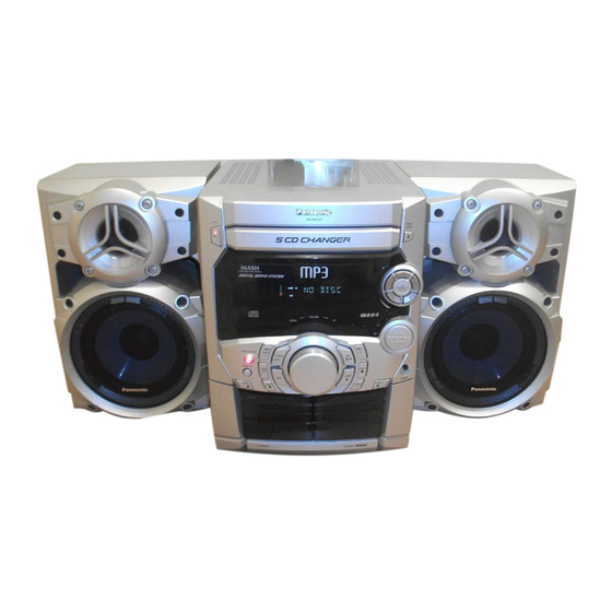
SA-AK220GCP
Colour
(S)... Silver Type
Erasing system
Tape speed
Overall frequency response (+3 dB, -6 dB at DECK OUT)
NORMAL (TYPE I)
S/N
Wow and flutter
Fast forward and rewind time
n CD SECTION
Sampling frequency
Decoding
Beam source/wavelength
Number of channels
Frequency response
Wow and flutter
Digital filter
D/A converter
MP3
Bit rate
Sampling frequency
n GENERAL
Power Supply
Power consumption
Power consumption in standby
mode
Dimensions (W x H x D)
© 2004 Panasonic AVC Networks Singapore Pte.
Ltd. All rights reserved. Unauthorized copying and
distribution is a violation of law.
ORDER NO. MD0403067C3
CD Stereo System
AC erase 100 kHz
35 Hz - 14 kHz
50 dB (A weighted)
0.18 % (WRMS)
Approx. 120 seconds with
C-60 cassette tape
16 bit linear
Semiconductor laser/780 nm
20 Hz - 20 kHz (+1, -2 dB)
Below measurable limit
MASH (1 bit DAC)
32 kbps - 320 kbps
32 kHz, 44.1 kHz, 48 kHz
AC 110/ 127/ 220-230/ 240 V,
250 x 330 x 363 mm
4.8 cm/s
44.1 kHz
Stereo
8 fs
50/ 60 Hz
179 W
0.85 W
Advertisement
Table of Contents

Related Manuals for Panasonic SA-AK220GCP


Summary of Contents for Panasonic SA-AK220GCP
- Page 1 DC servo motor Dimensions (W x H x D) 250 x 330 x 363 mm Recording system AC bias 100 kHz © 2004 Panasonic AVC Networks Singapore Pte. Ltd. All rights reserved. Unauthorized copying and distribution is a violation of law.
-
Page 2: Table Of Contents
SA-AK220GCP Mass 7.5 kg Notes: n SYSTEM SC-AK220 (GCP) Music center: SA-AK220 (GCP) 1. Specifications are subject to change without notice. Mass and dimensions are approximate. Speaker: SB-AK220 (P) 2. Total harmonic distortion is measured by the digital spectrum analyzer. - Page 3 SA-AK220GCP 19 Wiring Connection Diagram 22 Troubleshooting Guide 20 Illustration of IC 痴, Transistors and Diodes 23 Parts Location and Replacement Parts List 21 Terminal Function of IC 痴 23.1. Deck Mechanism (RAA4502-S) 21.1. IC701 (AN22004A-NF) Servo Amplifier 23.2. CD Loading Mechanism (RD-DAC026-S) 21.2.
-
Page 4: Before Use
SA-AK220GCP 1 Before Use Be sure to disconnect the mains cord before adjusting the voltage selector. Use a minus(-) screwdriver to set the voltage selector (on the rear panel) to the voltage setting for the area in which the unit will be used. -
Page 5: Handling The Lead-Free Solder
SA-AK220GCP together of your clothes fabric or the lifting of your foot from a carpeted floor can generate static electricity (ESD) sufficient to damage an ES device). 5 Handling the Lead-free Solder 5.1. About lead free solder (PbF) Distinction of PbF P.C.B.: P.C.B.s (manufactured) using lead free solder will have a PbF stamp on the P.C.B. -
Page 6: Handling Precautions For Traverse Deck
SA-AK220GCP 6 Handling Precautions For Traverse Deck The laser diode in the traverse deck (optical pickup) may break down due to potential difference caused by static electricity of clothes or human body. So, be careful of electrostatic breakdown during repair of the traverse deck (optical pickup). -
Page 7: Precaution Of Laser Diode
SA-AK220GCP 7 Precaution of Laser Diode Caution : This product utilizes a laser diode with the unit turned "ON", invisible laser radiation is emitted from the pick up lens. Wavelength : 780 nm Maximum output radiation power from pick up : 100 µW/VDE Laser radiation from pick up unit is safety level, but be sure the followings: 1. -
Page 8: Accessories
SA-AK220GCP 8 Accessories Remote Control Transmitter FM Indoor Antenna AC Power Supply Cord AM Loop Antenna Power Plug Adaptor... -
Page 9: Operation Procedures
SA-AK220GCP 9 Operation Procedures... -
Page 10: Disassembly And Assembly Of Main Component
SA-AK220GCP 10 Disassembly and Assembly of Main Component 10.1. Disassembly flow chart The following chart is the procedure for disassembling the casing and inside parts for internal inspection when carrying out the servicing. To assemble the unit, reverse the steps shown in the chart as below. -
Page 11: Disassembly Of Top Cabinet And Rear Panel
SA-AK220GCP 10.2. Disassembly of Top Cabinet and Rear Panel Step 1 Remove 3 screws each side and 5 screws at rear panel. Step 4 Draw rear panel forward. Step 2 Lift up both sides of top cabinet, push the cabinet ass’y 10.2.1. - Page 12 SA-AK220GCP [Open the disc tray manually (Using service tools)] Step 5 Press the OPEN/CLOSE button, the disc tray will be close. Step 1 Insert the gear tool into the hole on the underside of CD chassis and then rotate in the direction of arrow. The disc tray will be open.
-
Page 13: Disassembly Of Cd Mechanism Unit
SA-AK220GCP direction. Step 4 The disc tray will be close. Step 3 Repeat Step 2 but rotate the gear tools in anti-clockwise 10.3. Disassembly of CD Mechanism Unit · Follow the (Step 1) - (Step 2) of Item 10.2 - Disassembly of Top Cabinet and Rear Panel ·... -
Page 14: Disassembly Main P.c.b., Transformer P.c.b., Voltage Selector P.c.b. & Power P.c.b
SA-AK220GCP 10.4. Disassembly Main P.C.B., Transformer P.C.B., Voltage Selector P.C.B. & Power P.C.B. 10.4.1. Disassembly for the Main P.C.B. 10.4.3. Disassembly of the Power P.C.B. · Follow the (Step 1) - (Step 5) of Item 10.2 - Disassembly of · Follow the (Step 1) - (Step 5) of Item 10.2 - Disassembly of... -
Page 15: Disassembly Of Panel P.c.b. & Tact Switch P.c.b
SA-AK220GCP Step 4 Fix back the cutted portion with a screw as shown. Step 3 Unsolder the terminals of Power Amp IC, transistor and replace the components. 10.5. Disassembly of Panel P.C.B. & Tact Switch P.C.B. · Follow the (Step 1) - (Step 2) of Item 10.2 - Disassembly of Top Cabinet and Rear Panel ·... -
Page 16: Disassembly Of Deck Mechanism Unit & Deck P.c.b
SA-AK220GCP Step 6 Pull out the volume knob. Step 7 Pull Panel P.C.B. forward. 10.6. Disassembly of Deck Mechanism Unit & Deck P.C.B. · Follow the (Step 1) - (Step 2) of Item 10.2 - Disassembly of Top Cabinet and Rear Panel ·... - Page 17 SA-AK220GCP Step 4 With pressing the claw (A), rotate the hexagonal wrench clockwise. (The slide plate R moves for a little amount.) Step 5 Pressing the claw (B) in the direction of arrow (1), the connection lever moves in the direction of arrow (2).
- Page 18 SA-AK220GCP Note: Be careful not to lose the 3 floating spring because those will also be removed on removal of the traverse deck ass’y. · Installation of the CD Servo P.C.B. after replacement Step 1 Connect the FFC board. Step 2 Install the CD servo P.C.B. in the traverse deck ass’y.
- Page 19 SA-AK220GCP Step 1 Install the traverse deck ass’y to the timing lever. Step 2 Align the boss of traverse deck ass’y with the slot of traverse cam gear. Step 3 Force the claw of timing lever. Step 5 With pressing the claw (B) in the direction of arrow (1), force the connection lever in the direction of arrow (2).
- Page 20 SA-AK220GCP Step 4 With lifting the claw in the direction of (1), draw the CD Step 8 Release the both claws, and then draw the disc tray. Detect P.C.B. in the direction of arrow (2). Step 5 Remove the mechanism cover.
- Page 21 SA-AK220GCP 10.7.3. Disassembly and reassembly for mechanism base drive unit Step 1 Remove 3 screws. Step 2 Holding the drive rack not to move, install the disc tray. Step 2 Release the claw, and then remove the gear holder. Step 3 Align the drive rack with the drive gear.
- Page 22 SA-AK220GCP Step 9 Pressing the claw (B) in the direction of arrow (1), force the connection lever in the direction of arrow (2). Step 6 Install the tray lock spring to hook temporary. Step 7 Release the claw, and then remove the tray lock.
- Page 23 SA-AK220GCP Step 13 Remove the traverse relay gear, traverse cam gear and drive gear. Step 11 Lift up the left end of spindle base unit in the direction of arrow (1), and then remove the unit in the direction of arrow (2).
- Page 24 SA-AK220GCP Step 3 Rotate the disc lever in the direction of arrow (1), draw the disc lever. NOTE: Hold the loading stopper ass’y manually bacause it is flipped by spring. NOTE: Take care not to lose the disc lever spring.
- Page 25 SA-AK220GCP Step 8 Release the 2 claws, and then remove the relay gear A. Step 9 Release the 2 claws, and then remove the spindle shaft. Step 12 Squeeze the shaft of lower hook, and then draw it. Step 13 Rotate the lower spindle in the direction of arrow until Step 10 Remove the lower spindle spring with tweezers.
- Page 26 SA-AK220GCP spread the hold bars of loading stopper and remove the Step 1 Install the traverse cam gear. UP/DOWN base. Step 2 Rotate the traverse cam gear to the direction of arrow. [Installation for loading stopper ass’y] Step 1 Align the claw of loading stoppers ass’y with the slot of spindle base.
- Page 27 SA-AK220GCP Step 4 Install the slide plate 2 to the mechanism base, and then match to the connection lever. Step 7 Move the slide plate 1 to forward fully. Step 5 Install the slide plate 1 to the mechanism base, and then match to the connection leve and align the trapezoid tooth Step 8 Install the rear lock.
- Page 28 SA-AK220GCP Step 14 Install the tray base, traverse ass’y, mechanism cover and upper plate. [Operation check after servicing] Check the proper operation of following items with gear and hexagonal screwdriver. 1. Open/close of tray base. 2. Moving the tray base to the stock side.
-
Page 29: Replacement For The Pinch Roller Ass 馳 And Head Block
SA-AK220GCP 10.8. Replacement for the pinch roller ass’y and head block · Follow the (Step 1) - (Step 2) of Item 10.2 - Disassembly of Top Cabinet and Rear Panel · Follow the (Step 1) - (Step 5) of Item 10.2.1 - Disassembly for CD Lid ·... -
Page 30: Replacement For The Deck Motor Ass 馳, Capstan Belt A, Capstan Belt B And Winding Belt
SA-AK220GCP Step 3 Remove 2 screws. 10.9. Replacement for the Deck motor ass’y, capstan belt A, capstan belt B and winding belt · Follow the (Step 1) - (Step 2) of Item 10.2 - Disassembly of Top Cabinet and Rear Panel ·... - Page 31 SA-AK220GCP Step 5 Remove the flywheel R. Step 6 Release the claw of tape side, and then remove the winding lever and spring. Step 7 Remove the flywheel F. [Installation of the belt] Step 1 The boss and marking should be positioned Step 2 Put the winding belt on the pulley temporarily.
- Page 32 SA-AK220GCP Step 7 Put the capstan belt A temporarily as shown below. Step 10 Remove 3 screws. Step 11 Put the capstan belt B as shown below. Step 8 Put the capstan belt B on the motor ass’y pulley. Step 12 Put the capstan belt A on the motor ass’y pulley.
-
Page 33: Replacement For The Cassette Lid Ass 馳
SA-AK220GCP 10.10. Replacement for the cassette 10.11. Counter- measure for tape lid ass’y trouble · Follow the (Step 1) - (Step 2) of Item 10.2 - Disassembly of · Follow the (Step 1) - (Step 2) of Item 10.2 - Disassembly of... -
Page 34: Service Position
SA-AK220GCP 11 Service Position 11.1. Checking Procedure Note: For the disassembling procedure, see Section 10. 11.2. Checking the Main P.C.B., Power P.C.B., Transformer P.C.B. and Voltage Selector P.C.B. 1. Disassembly of Top Cabinet and Rear Panel. 2. Disassembly of CD Lid. -
Page 35: Checking The Panel P.c.b., Tact Switch P.c.b., Deck P.c.b. & Deck Mechanism
SA-AK220GCP 11.3. Checking the Panel P.C.B., Tact Switch P.C.B., Deck P.C.B. & Deck Mechanism P.C.B. 1. Remove Top Cabinet and Rear Panel. 2. Remove CD Lid. 3. Remove CD Mechanism Unit. 4. Remove volume knob at front panel. 5. Remove Panel P.C.B. & Tact Switch P.C.B. -
Page 36: Description Of Error Code
SA-AK220GCP 12 Description of Error Code 12.1. Abnormality detection for Deck Mechanism block Abnormal Items Error Display Method of Detection MODE SW abnormal Normal operation during mecha transition, MODE SW abnormal is memorized. The content of abnormality can be confirmed in the abnormal detection mode explained in the later section. -
Page 37: Self-Diagnostic Function
SA-AK220GCP 13 Self-Diagnostic Function 13.1. Self-diagnostic display This unit is equipped with a self-diagnostic display function which, if a problem occurs, will display an error code corresponding to the problem. Use this function when performing maintenance on the unit. 13.2. How to enter the Self-Diagnostic Function 13.3. -
Page 38: Cd Mechanism Test (F15, F26, F16, F17, F27, F28, F29, H15)
SA-AK220GCP 13.4. CD Mechanism Test (F15, F26, F16, F17, F27, F28, F29, H15) 1. Press “CD”. 2. Press “OPEN/CLOSE (1)” and place a CD. 3. Press “OPEN/CLOSE (1)” to close the tray. 4. Press “OPEN/CLOSE (5)” and wait until the tray is open. -
Page 39: Cd Test Mode Function
SA-AK220GCP 14 CD Test Mode Function This CD test mode is provided to check CD unit without connecting to changer loading mechanism. This mode shall operate CD PLAY with CD unit being connected only and CD Automatic Alignment result is shown on FL display. -
Page 40: Measurements And Adjustments
SA-AK220GCP 15 Measurements and Adjustments 15.1. Cassette Deck Section standard value. Bias voltage for Deck 2 14±4mV (Normal) · Measurement Condition Erase voltage for Deck 2 80mV (Normal) − − − − Make sure head, capstan and press roller are clean. -
Page 41: Alignment Points
SA-AK220GCP 9. Set AM-SG to 520kHz. 10. Receive 520kHz in the unit. 11. Adjust Z101 (OSC) so that the EVM-DC value is with 1.1±0.5V. Fig.6 15.2.2. AM RF Adjustment 1. Connect the instrument as shown in Fig. 7. 2. Set the unit to AM mode. -
Page 42: Block Diagram
SA-AK220GCP 16 Block Diagram IC701 OPTICAL PICKUP AN22004A-NF SERVO AMP SEMICONDUCTOR LASER OFTR OFTR BDO/OFTR OFTCONT Q701 RFEQ LASER POWER DRIVE 3TENV (ENV) 3TOUT /RFDET /RFDET NRFDET RFAMP BandGap FEOUT PHOTO DETECTOR TEOUT IC703 AN8739SBTE2 FOCUS COIL/TRACKING COIL/ TRAVERSE MOTOR/... - Page 43 SA-AK220GCP TO MAIN BLOCK IC702 MN6627934CH SERVO PROCESSOR DIGITAL SIGNAL PROCESSOR/ DIGITAL FILTER/ D/A CONVERTER BLKCK 8~12, A0~10 9~19 15~19,21 A0~10 CTRL SUBCODE INTERFACE 2,3, D0~3 2,3,6,7 24,25 D0~3 /CAS DRAM INTERFACE IC704 C3ABMB000027 16M DRAM RFSW IREF DSLF PLLF...
- Page 44 SA-AK220GCP AM ANT FM ANT Z101 Z120 CF201 CF202 Q101 COIL COIL MIXER IF AMP RF AMP BUFFER (FM) DECODER RM AMP BUFFER PHASE PILOT CANCEL STEREO LEVEL S-CURVE SWITCH AM/FM COMP BUFFER TUNING DRIVE PILOT IC101 Z102 X102 LA1833NMNTLM...
- Page 45 SA-AK220GCP FROM POWER FL DISPLAY TRANSFORMER FL600 4,5,7,8,10,11,13,14,16,17,19,20, 3,6,9,12,15,18,21,24,27, 22,23,25,26,28,31,33,35,37,40 29,30,32,34,36,38,39 21~24,27~33 3~12,15~20 IC602 C0HBB0000040 FL DRIVER IC603 C0JBAE000192 C0GAM0000005 XOR GATE MOTOR DRIVE OUT1 OUT2 POWER SUPPLY CONTROL PLLDA Q303 STAT SWITCH PUSH Q324 PUSH MOTOR ST/DO SUPPLY SWITCH...
- Page 46 SA-AK220GCP IC1001 AN7348S-E1 P.B EQ/REC AMP/ ALC/TPS AMP (DECK 1) P.B. HEAD LCH 24(23) Q1014(Q1015) 1(2) 20(5) BUFFER 22(3) 21(4) (DECK 2) R/P HEAD LCH 17(8) 18(7) LOGIC L/H Q1012 Q1020 (Q1013) (Q1021) NOR/CrO & MUTING MUTING HI/LO LOGIC SWITCH...
- Page 47 SA-AK220GCP IC301 4(39) IN B1(2) C0AABB000117 HEADPHONE AMP 3(5) 1(7) 19(24) OUT1(2) Q401(Q201) 5(38) IN C1(2) SWITCH Q402 9(34) Q407 A_VOLIN1(2) (Q202) (Q207) MUTING MUTING IC300 SWITCH 8(35) SWITCH REC1(2) C1BB00000747 AUDIO SOUND PROCESSOR 6(37) IN D1(2) JK300 Q403(Q203) HEADPHONE...
- Page 48 SA-AK220GCP 10(14) 4(1) -IN L(R) OUT L(R) JK952 FULL RANGE IC501 +VCC RSN35H2A-P POWER HIC 11(13) +IN L(R) -VCC AC DET MUTE C LATCH IN GND FILTER -VCCM FILTER FILTER Q502,Q505 Q512,Q513 VOLTAGE SUPPLY/ DC_DET DC DETECT CURRENT CONTROL SWITCH...
-
Page 49: Schematic Diagram
SA-AK220GCP 17 Schematic Diagram · Put a conductive mat on the work table. (All schematic diagrams may be modified at any time with the development of the new technology) · Ground the soldering iron. Note: · Do not touch the pins of IC, LSI or VLSI with fingers directly. -
Page 50: A) Cd Servo Circuit
SA-AK220GCP 17.1. (A) CD Servo Circuit SCHEMATIC DIAGRAM - 1 : +B SIGNAL LINE : CD-DA SIGNAL LINE OPTICAL PICKUP CIRCUIT CD SERVO CIRCUIT R701 C770 Q701 B1ADCF000001 C701 Q701 6.3V33 LASER POWER DRIVE C703 6.3V100 C704 RF VOLT C716... - Page 51 SA-AK220GCP SCHEMATIC DIAGRAM - 2 : +B SIGNAL LINE : CD-DA SIGNAL LINE : CD SIGNAL LINE CD SERVO CIRCUIT R721 R717 C727 C725 50V1 1000P R718 C726 1000P C728 50V1 C731 C730 6.3V220 C757 LCH OUT 6.3V100 A.GND RCH OUT +3.3V...
-
Page 52: B) Tuner/Main Circuit
SA-AK220GCP 17.2. (B) Tuner/Main Circuit SCHEMATIC DIAGRAM - 3 : +B SIGNAL LINE : FM SIGNAL LINE : AM SIGNAL LINE : FM/AM SIGNAL LINE : FM OSC SIGNAL LINE : AM OSC SIGNAL LINE TUNER/MAIN CIRCUIT R104 TUNER PACK CIRCUIT... -
Page 53: B) Main Circuit
SA-AK220GCP 17.3. (B) Main Circuit SCHEMATIC DIAGRAM - 4 : PLAYBACK SIGNAL LINE : AUX SIGNAL LINE : +B SIGNAL LINE PANEL CIRCUIT (CP601) ON : RECORD SIGNAL LINE : MAIN SIGNAL LINE SCHEMATIC DIAGRAM-10 MAIN CIRCUIT CN303 CR02 MOTOR... - Page 54 SA-AK220GCP SCHEMATIC DIAGRAM - 5 : CD SIGNAL LINE : MAIN SIGNAL LINE : +B SIGNAL LINE PANEL CIRCUIT : -B SIGNAL LINE (CP602) ON SCHEMATIC DIAGRAM-10 MAIN CIRCUIT CN302 24 25 26 27 28 29 30 R820 Q203, Q403...
- Page 55 SA-AK220GCP SCHEMATIC DIAGRAM - 6 : +B SIGNAL LINE MAIN CIRCUIT Q312 Q316 B1GBCFJJ0039 B1ACCF000063 PCONT SWITCH SWITCH Q312 C352 100P R392 C351 100P R338 R805 C353 4.7K 100P Q317 C350 R367 C354 100P 100P Q316 R816 R383 470K R815...
- Page 56 SA-AK220GCP SCHEMATIC DIAGRAM - 7 : +B SIGNAL LINE MAIN CIRCUIT R358 R353 R355 8.2K R359 4.7K C339 R352 R360 0.01 R356 4.7K R315 Q303 8.2K R314 B1ABCF000131 4.7K SWITCH R313 Q302 4.7K R320 C338 R318 R351 0.01 8.2K Q302...
- Page 57 SA-AK220GCP SCHEMATIC DIAGRAM - 8 : +B SIGNAL LINE : AUX SIGNAL LINE : MAIN SIGNAL LINE : -B SIGNAL LINE : CD SIGNAL LINE : PLAYBACK SIGNAL LINE : RECORD SIGNAL LINE : FM/AM SIGNAL LINE MAIN CIRCUIT C303...
-
Page 58: C) Panel Circuit & (D) Tact Switch Circuit
SA-AK220GCP 17.4. (C) Panel Circuit & (D) Tact Switch Circuit SCHEMATIC DIAGRAM - 9 : MAIN SIGNAL LINE : +B SIGNAL LINE : -B SIGNAL LINE PANEL CIRCUIT TACT SWITCH CIRCUIT SYS6V R600 S910 4.7K DISPLAY R909 S612 D600 B3AAA0000583... - Page 59 SA-AK220GCP SCHEMATIC DIAGRAM - 10 : +B SIGNAL LINE : -B SIGNAL LINE : MAIN SIGNAL LINE PANEL CIRCUIT C641 R693 SEG 16 35V22 GRID11 SEG15 D613 R692 B0BA7R200003 GRID10 C640 SEG 14 50V3.3 GRID9 L601 SEG13 G0C101JA0044 -VP_A GRID8...
-
Page 60: F) Cd Detect Circuit, (G) Spindle Position Circuit & (H) Cd Loading Circuit
SA-AK220GCP 17.5. (F) CD Detect Circuit, (G) Spindle Position Circuit & (H) CD Loading Circuit SCHEMATIC DIAGRAM - 11 : +B SIGNAL LINE C0GAM0000005 MOTOR DRIVE 0.01 16V100 B0BA4R600003 CD DETECT CIRCUIT PLUNGER BOTTOMSW POSITION PSLED D_GND PUSH MAIN CIRCUIT... -
Page 61: E) Transformer Cuircuit & (L) Voltage Selector Circuit
SA-AK220GCP 17.6. (E) Transformer Cuircuit & (L) Voltage Selector Circuit SCHEMATIC DIAGRAM - 12 : +B SIGNAL LINE : -B SIGNAL LINE S950 K0AFZA000005 VOLTAGE SELECTOR CIRCUIT TRANSFORMER CIRCUIT VCC+ D952 VCC- D953 POWER D950~D953 CIRCUIT B0EAMM000038 AC GND (H950/... -
Page 62: I) Power Circuit
SA-AK220GCP 17.7. (I) Power Circuit SCHEMATIC DIAGRAM - 13 : -B SIGNAL LINE : MAIN SIGNAL LINE : +B SIGNAL LINE POWER CIRCUIT IC501 IC501 RSN35H2A-P C501 0.01 R450 C240 470P 330K C450 C443 C442 100V10 470P GND_L GND_R C440... -
Page 63: J) Deck Circuit & (K) Deck Mechanism Circuit
SA-AK220GCP 17.8. (J) Deck Circuit & (K) Deck Mechanism Circuit SCHEMATIC DIAGRAM -14 : +B SIGNAL LINE : PLAYBACK SIGNAL LINE : RECORD SIGNAL LINE DECK CIRCUIT R1038 R1039 R1055 C1038 4.7K 2.2K 220P C1044 10V33 C1057 R1015 C1034 R1029 1000P 50V3.3... - Page 64 SA-AK220GCP SCHEMATIC DIAGRAM - 15 : PLAYBACK SIGNAL LINE : +B SIGNAL LINE : RECORD SIGNAL LINE MAIN CIRCUIT (CN304) ON SCHEMATIC DIAGRAM-4 DECK CIRCUIT CN1001 Q1017 B1AARC000002 50V3.3 C1054 MOTOR SWITCH C1064 50V3.3 R1091 R1095 2.2K 100K R1098 R1057...
-
Page 65: Printed Circuit Board
SA-AK220GCP 18 Printed Circuit Board Note: Circuit board diagrams may be modified at any time with the development of new technology. 18.1. (A) CD Servo P.C.B. (Side A & Side B) CD SERVO P.C.B (REPX0405A) TP16 TP30 C770 TP24 R743... - Page 66 SA-AK220GCP CD SERVO P.C.B (REPX0405A) R761 R762 R763 IC704 R760 C752 R715 C715 (SIDE B)
-
Page 67: B) Main
SA-AK220GCP 18.2. (B) Main P.C.B. MAIN P.C.B (REPX0422S) FM ANT AM ANT JK300 W480 L305 C443 JK101 W131 W130 R401 R456 R112 C107 R256 To Tuner Pack P.C.B R448 R455 W100 R433 C421 R423 R429 C440 D401 R432 Z101 R427... - Page 68 SA-AK220GCP AM ANT W130 W210 W127 W126 W249 Q106 C302 W264 W121 W255 W120 W265 C109 W132 W487 R131 W116 R144 W314 R118 C106 C126 Q308 W111 R326 C321 R327 IC101 C119 C131 C115 D308 R121 W380 W103 D309 W486...
-
Page 69: C) Panel
SA-AK220GCP 18.3. (C) Panel P.C.B. PANEL P.C.B (REPX0426B) S601 OPEN/ CLOSE R601 R602 S602 SENSOR S603 FL600 W678 S606 2 3 4 5 6 7 8 9 10 11 12 13 14 15 16 17 18 19 20 21 22 23 24 25 26 27 28 29 30 31 32 33 34 35 36 37 38 39 40 41 42 43... - Page 70 SA-AK220GCP D600 S612 POWER W679 C642 W680 W684 C682 C674 CP601 IC603 R634 R635 1 23 R976 C924 C923 W616 W630 W622 9 11 13 15 14 16 22 24 26 28...
-
Page 71: D) Tact P.c.b. & (M) Voltage Selector
SA-AK220GCP 18.4. (D) Tact P.C.B. & (M) Voltage Selector P.C.B. TACT P.C.B (REPX0426B) S615 S616 S909 S906 R905 R909 DECK1/2 DECK1 DECK2 R906 R614 R615 CP900 S908 S907 R908 S614 TAPE 2 3 4 5 6 7 8 9 10... -
Page 72: E) Transformer
SA-AK220GCP 18.5. (E) Transformer P.C.B. TRANSFORMER P.C.B (REPX0324J) C963 T951 (SUB-TRANSFORMER) Q952 R957 Q953 C954 C962 J920 R951 F1 T2AL 250 J918 C964 C952 Q954 T950 (POWER TRANSFORMER) C953 Q950 C960 CN951 C958 Q951 D952 C957 D950 FP951 D953 D958... - Page 73 SA-AK220GCP (BLACK) F1 T2AL 250V JK950 J989 J988 AC IN ER TRANSFORMER) 110V/127V/ 220-230V/240V J990 50Hz/60Hz J987 J912 (ORANGE) RL950 (RED) (VIOLET) (BLUE) D965 (ORANGE) PRIMARY IS P.C.B...
-
Page 74: F) Cd Detect P.c.b., (G) Spindle Position P.c.b., (H) Cd
SA-AK220GCP 18.6. (F) CD Detect P.C.B., (G) Spindle Position P.C.B., (H) CD Loading P.C.B. & (L) Tuner Pack P.C.B. CD LOADING P.C.B (REP2578A-N) OPEN PUSH PUSH CD DETECT P.C.B SPINDLE POSITION P.C.B (REP2578A-N) (REP2578A-N) LOAD TUNER PACK P.C.B (REP1999B) -
Page 75: I) Power
SA-AK220GCP 18.7. (I) Power P.C.B. POWER P.C.B (REPX0328J) H950 W950 Q501 Q504 J509 R514 R523 Q503 Q502 R513 D501 FP533 C504 C509 C506 R528 J570 J535 J569 C511 J508 R525 J534 R517 C505 D502 J525 R450 J546 R526 C521 J564... - Page 76 SA-AK220GCP IC501 J508 D502 R450 C521 R546 R251 R455 J578 C447 J579 C446 JK952 R246 J583 C246 J561 9 10 11 12 CN500...
-
Page 77: J) Deck P.c.b. & (K) Deck Mechanism
SA-AK220GCP 18.8. (J) Deck P.C.B. & (K) Deck Mechanism P.C.B. DECK P.C.B. DECK MECHANISM P.C.B. (REPX0331A) (REPX0321A) IC1004 Q1001 C1006 C1009 R1005 R1006 C1003 J1000 CS1002 TP10 L1002 J1002 TP11 R1001 Q1007 R1004 TP12 C1002 J1003 C1026 C1011 C1021 C1020... - Page 78 SA-AK220GCP 19 Wiring Connection Diagram FM ANT AM ANT H950/W950 JK101 Z120 JK300 CD LOADING P.C.B CN501 SOLDER SIDE Z101 MAIN CN300 TUNER PACK P.C.B SOLDER SIDE P.C.B SOLDER SIDE Z102 CN305 CD DETECT P.C.B SOLDER SIDE POWER P.C.B SOLDER SIDE...
- Page 79 SA-AK220GCP 20 Illustration of IC’s, Transistors and Diodes AN7348S-E1 (24P) C0GAM0000005 (10P) C0AABB000117 (8P) C1AA00000612 (5P) C0HBB0000040 (48P) C1BB00000747 (42P) MN6627934CH (80P) C3ABMB000027 (26P) C2CBJF000017 (100P) LA1833NMNTLM (24P) LC72131MDTRM (20P) AN22004A-NF (32P) RSN35H2A-P (14P) CNB13030R2AU KRC102MTA AN8739SBTE2 (26P) B1ABCF000131 C0JBAE000192 (5P)
- Page 80 SA-AK220GCP 21 Terminal Function of IC’s 21.1. IC701 (AN22004A-NF) Servo Pin No. Mark Function DVSS2 Ground for digital circuits Amplifier DVDD2 Power supply digital cirfcuits Pin No. Mark Function SPOUT Spindle motor drive signal APC Amp input output (absolute value output)
- Page 81 SA-AK220GCP Pin No. Mark Function Pin No. Mark Function MDATA Micro controller command PVCC2 Power supply (2) for driver data signal input Power supply terminal Micro controller command VREF Reference voltage input load signal input Motor driver (4) input Low: Load...
- Page 82 SA-AK220GCP Pin No. Mark Function Pin No. Mark Function No connection AVcc Analog power supply input PCONT/EFP_ Main transformer control output DEMO (H= default demo on, L= default SELECTOR demo off.) DCDET DC detect input SP_A Speana control output A...
- Page 83 SA-AK220GCP 22 Troubleshooting Guide...
- Page 84 SA-AK220GCP 23 Parts Location and Replacement Parts List Notes: · Important safety notice: Components identified by mark have special characteristics important for safety. Furthermore, special parts which have purposes of fire-retardent (resistors), high-quality sound (capacitors), low noise (resistors), etc are used.
- Page 85 SA-AK220GCP 23.1. Deck Mechanism (RAA4502-S) 23.1.1. Deck Mechanism Parts Location...
- Page 86 SA-AK220GCP...
- Page 87 SA-AK220GCP 23.1.2. Deck Mechanism Parts List Ref. No. Part No. Part Name & Description Remarks CASSETTE DECK RED0069 R/P HEAD BLOCK UNIT RED0070 P/B HEAD BLOCK UNIT RDG0300 REEL BASE GEAR RDG0301 WINDING RELAY GEAR RDK0026 MAIN GEAR RDV0033-4 WINDING BELT...
- Page 88 SA-AK220GCP 23.2. CD Loading Mechanism (RD-DAC026-S) 23.2.1. CD Loading Mechanism Parts Location...
- Page 89 SA-AK220GCP...
- Page 90 SA-AK220GCP 23.2.2. CD Loading Mechanism Parts List Ref. No. Part No. Part Name & Description Remarks Ref. No. Part No. Part Name & Description Remarks TRAVERSE DECK XTN2+6G SCREW RMX0141 PUSH SPACER RML0517 TIMING LEVER RMQ0749 UPPER SPINDLE RML0516 PLUNGER LEVER...
- Page 91 SA-AK220GCP 23.3. Cabinet 23.3.1. Cabinet Parts Location...
- Page 92 SA-AK220GCP...
- Page 93 SA-AK220GCP...
- Page 94 SA-AK220GCP 23.3.2. Cabinet Parts List Ref. No. Part No. Part Name & Description Remarks Ref. No. Part No. Part Name & Description Remarks CABINET AND CHASSIS RKA0059-K LEG RUBBER RKFX0093-KJ CASS HOLDER L REEX0202 10P FFC RKFX0094-KJ CASS HOLDER R...
- Page 95 SA-AK220GCP Ref. No. Part No. Part Name & Description Remarks Ref. No. Part No. Part Name & Description Remarks Q506 B1GCCFGA0005 TRANSISTOR D951 B0EAMM000038 DIODE Q507 KTC3199GRTA TRANSISTOR D951 MA2C16500E DIODE Q508 B1AAKD000009 TRANSISTOR D952 B0EAMM000038 DIODE Q512 B1AAGC000007 TRANSISTOR...
- Page 96 SA-AK220GCP Ref. No. Part No. Part Name & Description Remarks Ref. No. Part No. Part Name & Description Remarks CN309 RJS1A9414-1 14P CONNECTOR EYF52BC FUSE HOLDER CN310 K1MN19A00026 FFC CONNECTOR EYF52BC FUSE HOLDER CN500 K1KA12A00184 12P CONNECTOR EYF52BC FUSE HOLDER...
- Page 97 SA-AK220GCP Ref. No. Part No. Part Name & Description Remarks Ref. No. Part No. Part Name & Description Remarks R111 ERJ3GEYJ391V 390 1/16W R246 ERDS2TJ153T 15K 1/4W R112 ERJ3GEYJ104V 100K 1/16W R247 ERDS2TJ562T 5.6K 1/4W R113 ERJ3GEYJ103V 10K 1/16W R248 D0GB4R7JA008 4.7 1/16W...
- Page 98 SA-AK220GCP Ref. No. Part No. Part Name & Description Remarks Ref. No. Part No. Part Name & Description Remarks R399 ERJ3GEYJ103V 10K 1/16W R510 ERDS2TJ272T 2.7K 1/4W R400 ERJ3GEYJ103V 10K 1/16W R511 ERDS2TJ561T 560 1/4W R401 ERJ3GEYJ103V 10K 1/16W R512 ERDS2TJ272T 2.7K 1/4W...
- Page 99 SA-AK220GCP Ref. No. Part No. Part Name & Description Remarks Ref. No. Part No. Part Name & Description Remarks R727 D0GB152JA002 1.5K 1/16W R959 ERD2FCVJ4R7T 4.7 1/4W R728 D0GB183JA002 18K 1/16W R960 ERDS2TJ472T 4.7K 1/4W R729 D0GB152JA002 1.5K 1/16W R961...
- Page 100 SA-AK220GCP Ref. No. Part No. Part Name & Description Remarks Ref. No. Part No. Part Name & Description Remarks ECBT1E103ZF5 0.01 25V C222 ERJ3GEY0R00V 0 1/16W RCBS1H102KBY 1000P 50V C223 ECJ1VC1H101K 100P 50V ECBT1H2R2KC5 2.2P 50V C224 ECEA1HKA010B 1 50V...
- Page 101 SA-AK220GCP Ref. No. Part No. Part Name & Description Remarks Ref. No. Part No. Part Name & Description Remarks C405 ECJ1VB1H221K 220P 50V C682 ECBT1H101KB5 100P 50V C406 ECEA1CKA100B 10 16V C701 ECEA0JKA330I 33 6.3V C407 ECEA1CKA100B 10 16V C702 ECJ1VB0J474K 0.47 6.3V...
- Page 102 SA-AK220GCP Ref. No. Part No. Part Name & Description Remarks Ref. No. Part No. Part Name & Description Remarks C959 ECKR2H103ZF5 0.01 500V C1037 ECEA1HKA3R3B 3.3 50V C960 ECQE1104KF3 0.1 100V C1038 ECJ1VB1H221K 220P 50V C961 ECA1CM102B 1000 16V C1039...
- Page 103 SA-AK220GCP 23.6. Packaging PRT0401 D/K/J/N/L...