Table of Contents
Advertisement
Advertisement
Table of Contents

Related Manuals for Bosch OBD 100


Summary of Contents for Bosch OBD 100
- Page 1 OBD 100 en Original instructions EOBD & CAN Scan Tool...
- Page 2 2 | OBD 100 | Content English Symbols used Operation In the documentation Safety information Connection to vehicle 1.1.1 Warning notices - Structure and meaning 3 Functions in main menu 1.1.2 Symbols in this documentation On the product Codes (trouble codes) 5.4.1 Reading trouble codes...
-
Page 3: Symbols Used
Warning notices - functions of the OBD 100 and contain step-by- Structure and meaning step directions for use of the OBD 100. Study Warning notices warn of dangers to the user and observe these operating instructions in full or people in the vicinity. Warning notices also before using the OBD 100. -
Page 4: Product Description
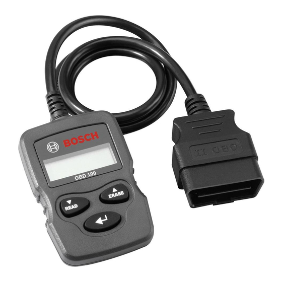
Fig. 2: OBD 100 buttons Button Function The OBD 100 is only to be used with the R Scrolls down through the screen dis- vehicle stationary. Use whilst driving is READ play when ↓ or ↕ appears on the prohibited. - Page 5 All you need to know about OBD | OBD 100 | 5 All you need to know The following are monitored once per drive about OBD cycle: Lambda sensor function Catalytic converter function What are OBD, OBD II, OBD-2 and EOBD...
- Page 6 6 | OBD 100 | All you need to know about OBD What are trouble codes 4.5.2 Stored trouble codes The OBD trouble codes (DTC) are defined in Stored trouble codes (DTC) are trouble codes SAE J2012 and ISO 15031-6. Manufacturer-...
-
Page 7: Operation
All you need to know about OBD | OBD 100 | 7 Operation 4.5.6 Erasing trouble codes "Erase trouble codes" erases all pending and Safety information confirmed codes from the fault memory. Before erasing trouble codes it must be The OBD 100 can only read and recognize... - Page 8 4. Insert the OBD diagnostic connector of the ¶ Pull the OBD diagnostic connector and not OBD 100 in the OBD diagnostic socket of the the cable to disconnect the OBD 100 from vehicle. the vehicle. The OBD 100 is switched on.
- Page 9 Reading trouble codes 1. Switch on the ignition (position 2). The function "Erase trouble codes" is not to 2. Connect the OBD 100 to the vehicle. be performed until the systems have been Data are read. fully checked and the trouble codes written 3.
- Page 10 (PID) of the vehicle electronic control unit to be displayed in real time. A list of the PIDs Permanent codes can only be erased by the supported by the OBD 100 is given in Section 9. vehicle. All values are displayed in metric units.
- Page 11 1. Switch on the ignition (position 2). operation of the malfunction indicator light. 2. Connect the OBD 100 to the vehicle Data are read in. 1. Switch on the ignition (position 2).
-
Page 12: Freeze Frame (Data)
PIDs. A list of the PID numbers (parameter press the <READ> button. Make sure the ignition key is set IDs) supported by the OBD 100 is given in to ON (position 2) and not to Section 9. ACCESSORIES (position 1). -
Page 13: Technical Data
Storage and transportation 20 % – 80 % and possible health hazards. Function 20 % – 80 % Electromagnetic compatibility (EMC) The OBD 100 is a class B product as per EN 61 326-1. Robert Bosch GmbH 569624 Rev "A" 2013-12-19... - Page 14 14 | OBD 100 | Glossary Glossary The data represent a sort of snapshot of the prevailing operating and ambient conditions at Confirmed code the moment in time at which the trouble was If a pending code is confirmed in the second detected.
-
Page 15: Malfunction Indicator Light
OBD-2 (EOBD) was introduced for new vehicles the vehicle identification number displayed in with gasoline engine in January 2001 with the the OBD 100 must coincide with the vehicle EURO-3 standard and for diesel passenger identification number of the vehicle. Matching vehicles in January 2003. -
Page 16: Pid Definitions
16 | OBD 100 | PID definitions PID definitions PID description Boost Pressure Sensor A, BP_A_ACT, B_ACT PID description Sensor B ABS FRP Absolute Fuel Rail Pressure Commanded Boost Pressure A, BP_A_CMD, B_CMD Pressure B ABS LOAD Absolute Load Value... - Page 17 PID definitions | OBD 100 | 17 PID description PID description Exhaust Gas Recirculation FUEL_TIMING Fueling Injection Timing EGRT 11, 21 Temperature Bank 1 Sensor 1, GPL_STAT Glow Plug Lamp Status Bank 2 Sensor 1 Exhaust Gas Recirculation Commanded Intake Air Flow A...
- Page 18 18 | OBD 100 | PID definitions PID description PID description SCR inducement system actual SCR inducement system actual state 10K history HI1 (0-10000 state 10K history WRONG1 SCR REAG km), 10K history HI2 (10000- (0 - 10000 km), 10K history...
- Page 19 PID definitions | OBD 100 | 19 PID description Variable Geometry Turbo A VGT_A_ACT, B_ACT Position, Turbo B VGT_A_CMD, B_ Commanded Variable Geometry Turbo A Position, Turbo B VGT_A_STAT, B_ Variable Geometry Turbo A STAT Control Status, Turbo B VPWR...
- Page 20 Robert Bosch GmbH Diagnostics Franz-Oechsle-Straße 4 73207 Plochingen DEUTSCHLAND www.bosch.com bosch.prueftechnik@bosch.com 569624 Rev "A" | 2013-12-19...