Table of Contents
Advertisement
Advertisement
Table of Contents

Related Manuals for Husqvarna PG 280 S


Summary of Contents for Husqvarna PG 280 S
- Page 1 Workshop manual PG 280 S English 1022 - 002 -...
-
Page 2: Table Of Contents
3.2 Tightening torques ..........6 4 Servicing tools 4.1 Servicing tools overview.........7 5 Product overview for repair and servicing 5.1 Component overview PG 280 S......8 5.2 Component overview electrical enclosure....9 5.3 Component view of the motor connection box PG 280 S 1-phase............10 6 Repair and servicing 6.1 Motor.............. -
Page 3: Introduction
WARNING: All personnel that repair or do servicing on the product must read and understand the safety instructions in this workshop manual. 1.5 Servicing tools The manual gives information about necessary servicing tools. Always use original tools from Husqvarna. 1022 - 002 - Introduction - 3... -
Page 4: Safety
2 Safety 2.1 Safety definitions 2.3 Symbols on the product Warnings, cautions and notes are used to point out WARNING: Not careful or incorrect use specially important parts of the manual. can result in injury or death to the operator or others. -
Page 5: Servicing Data
3 Servicing data 3.1 Symbols in the diagrams Tightening torque, Nm 1022 - 002 - Servicing data - 5... -
Page 6: Tightening Torques
3.2 Tightening torques 6 - Servicing data 1022 - 002 -... -
Page 7: Servicing Tools
4 Servicing tools 4.1 Servicing tools overview Designation Used for Order No./ Source tion Thread lock medium To assemble the motor and grinding head. To assemble the tool holder. Grease To assemble the motor and grinding head. Multimeter To control the functions of the electrical system Amprobe 37XR- ®... -
Page 8: Product Overview For Repair And Servicing
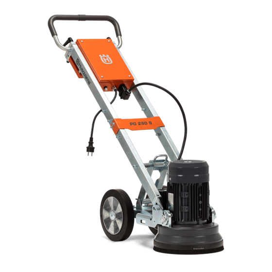
5 Product overview for repair and servicing 5.1 Component overview PG 280 S 1. Handle/Handlebar 9. Lock bolt to attach the motor/grinding head 2. Lock knobs for handlebar adjustment 10. Grinding head cover 3. ON/OFF switch 11. Electric motor 4. Electrical enclosure 12. -
Page 9: Component Overview Electrical Enclosure
5.2 Component overview electrical enclosure 1. Electrical enclosure 5. Connection to mains plug 2. ON/OFF switch 6. Resettable fuse 3. Ground points 7. Terminal block 4. Motor cable connector 1022 - 002 - Product overview for repair and servicing - 9... -
Page 10: Component View Of The Motor Connection Box Pg 280 S 1-Phase
5.3 Component view of the motor connection box PG 280 S 1-phase 1. Motor connection box 2. Electronic motor starter switch 3. Connection bridge 4. Motor run capacitor 5. Connection bridge 6. Connection to electrical enclosure 7. Ground point 8. Motor start capacitor... -
Page 11: Repair And Servicing
6 Repair and servicing 6.1 Motor 3. Remove the motor and grinding head from the frame. 6.1.1 To remove the motor and grinding head 1. Remove the cable from the connector. 2. Remove the retaining pin (A) and remove the clevis pin (B). -
Page 12: Grinding Head
6.2 Grinding head 3. Remove the tool holder assembly from the motor shaft slowly to prevent damage to the vibration damping units. 6.2.1 To remove the grinding head To remove the tool holder assembly, use an internal Servicing tools puller and an extension. Refer to overview on page 7 . - Page 13 5. Remove the parts that hold the dust cover, spacer 7. Remove the spring pins in the grinding head and motor. bracket. 8. Remove the dust cover from the motor bracket. 6. Remove the dust cover and the spacer. 6.2.2 To assemble the grinding head and the motor •...
-
Page 14: Troubleshooting
7 Troubleshooting 7.1 Function tests 3. Start the motor with the start/stop switch. The motor must then be at its operation speed in less than 5 The function tests show the condition of the electrical seconds. system, the motor and the grinding head. 4. -
Page 15: The Motor Does Not Start
7.6 The motor does not start ERROR: The electric motor is not starting up or the start up trial is interrupted. Is the fuse in the Let the motor cool down. The power source blowing overload protection is automatically when trying to start reset after a couple of minutes. - Page 16 Can the motor/ grinding disc easily be rotated by hand? ACTION: Attention! The machine Replace the electric must be motor. unplugged and the grinding tools removed! Is the fuse in the power source blowing when the motor cable is disconnected from the electrical cabinet during start up? Is the cable and plug between the...
-
Page 17: The Motor Stops
7.7 The motor stops ERROR: The electric motor stops during operation. ACTION: Check the wires and connections in the Has the fuse in the Has the thermistor electrical cabinet and the power source blown? fuse blown? motor connection box with help from the wiring diagram. -
Page 18: Diagrams
8 Diagrams 8.1 Wiring diagram Electrical Box Door SWITCH CONNECTION BLOCK THERMISTOR MOTOR -Harting CONNECTOR BLUE GRN/Y POWER CONNECTOR 1 Blue 2 Brown 3 Green/Yellow Motor BLUE WHITE ELECTRONIC CENTRIFUGAL SWITCH CONNECTION BLOCK START CAPACITOR RUN CAPACITOR 18 - Diagrams 1022 - 002 -... -
Page 19: Technical Data
9 Technical data 9.1 Electrical specifications Motor p/n Cert. Voltage (V) Frequency Power (kW) Pha- Poles Flange size R. Ca- S. Ca- (Hz) pacitor pacitor μF/VA μF/VA 597048201 40/450 150/250 597048202 40/450 200/250 1022 - 002 - Technical data - 19... - Page 20 2019-04-23...