
Related Manuals for Samsung RT4401-48A


Summary of Contents for Samsung RT4401-48A
- Page 1 RT4401-48A Installation Manual <Replace this text with a short document summary of no more two or three lines> Document Version 3.0 February 2019 Document Number: 2600-00NETNGAA...
- Page 2 SAMSUNG Electronics Co., Ltd., its subsidiaries or employees for any direct or indirect loss or damage caused by omissions from or inaccuracies in this document. SAMSUNG Electronics Co., Ltd. reserves the right to change details in this publication without notice. SNMTC-v3-0312 This manual should be read and used as a guideline for properly installing and/or operating the product.
-
Page 3: Table Of Contents
Guidelines for Cable Connections ....................81 Cable Path Inspection ........................ 81 Cable Cutting ..........................82 Cable Installation ........................82 Cable Binding ..........................83 Connector Attachment....................... 83 Identification Tag Attachment ....................84 Cabling Diagram ..........................85 RT4401-48A Installation Manual v3.0 Copyright © 2019, All Rights Reserved. - Page 4 Inspect the Installation Appendix A Acronyms Appendix B Clean the Optical Connectors Introduction ..........................131 Measure the Optical Output and Connecting the Optical Connector ........131 Appendix C Standard Torque RT4401-48A Installation Manual v3.0 Copyright © 2019, All Rights Reserved.
- Page 5 Fixing Mounting Bracket on the Pole (1) ..................48 Figure 46. Fixing Mounting Bracket on the Pole (2) ..................49 Figure 47. Fixing Mounting Bracket on the Pole (3) ..................49 RT4401-48A Installation Manual v3.0 Copyright © 2019, All Rights Reserved.
- Page 6 Connecting AC/DC Power Unit AC Power Cable (2) ............... 98 Figure 98. Connecting AC/DC Power Unit AC Power Cable (3) ............... 98 Figure 99. Connecting DC Power Cable (1) ....................100 RT4401-48A Installation Manual v3.0 Copyright © 2019, All Rights Reserved.
- Page 7 Figure 125. Connecting RF Cable (7) ....................... 123 Figure 126. Assembling Cable Cover (1) ......................124 Figure 127. Assembling Cable Cover (2) ......................125 Figure 128. Installation Inspection Procedure ....................126 RT4401-48A Installation Manual v3.0 Copyright © 2019, All Rights Reserved.
- Page 8 RF Cable Minimum Radius of Curvature ..................118 Table 46. Parts and Tools for connecting RF cable ..................118 Table 47. Parts and Tools for Assembling Cable Cover ................124 RT4401-48A Installation Manual v3.0 viii Copyright © 2019, All Rights Reserved.
- Page 9 Construction Situation Checklist ....................127 Table 49. Standard Torque Value for Fastening Bolts ................. 133 Table 50. Brass Bolts Torque Value......................133 Table 51. Connector Connection Torque Value ................... 133 RT4401-48A Installation Manual v3.0 Copyright © 2019, All Rights Reserved.
-
Page 10: Preface
Preface This manual describes how to install the RT4401-48A (CBRS RRH) including how to connect cables. This manual includes the following RRH: Conventions in this Document Samsung Networks product documentation uses the following conventions. Symbols Symbol Description Indicates a task. -
Page 11: New And Changed Information
This annex describes the procedure of cleaning the optical connector and cleaning tool. Appendix C Standard Torque This annex describes the standard torque when fastening the bolt. Related Documentation LTE eNB System Description RT4401-48A Installation Manual v3.0 Copyright © 2019, All Rights Reserved. -
Page 12: Personal And Product Safety
Each power feed to the unit requires a separate fused feed from the provided power supply. The cable between the power distribution point and the installed equipment must have a minimum cross-sectional area of 2.5 mm RT4401-48A Installation Manual v3.0 Copyright © 2019, All Rights Reserved. - Page 13 The product must remain grounded continuously unless all connections to the power supply and data network are all removed. If equipment is grounded through a cabinet or rack, make sure it is done so properly. RT4401-48A Installation Manual v3.0 xiii Copyright © 2019, All Rights Reserved.
- Page 14 Devices that are not marked according to the relevant national safety standards may produce hazardous conditions on the network. Product Disposal To reduce the environmental impact of products, Samsung has joined WEEE compliance activities. The WEEE symbol on the product indicates that the product is covered by the European Directive 2002/96/CE for the disposal of Waste Electrical and Electronic Equipment (WEEE).
- Page 15 Any changes or modifications not expressly approved by the party responsible for compliance could void the user's authority to operate this equipment. RT4401-48A Installation Manual v3.0 Copyright © 2019, All Rights Reserved.
-
Page 16: Equipment Markings
This product and its electronic accessories should not be mixed with other commercial wastes for disposal. Protective earth RRH AC/DC power unit should be grounded. RT4401-48A Installation Manual v3.0 Copyright © 2019, All Rights Reserved. -
Page 17: Chapter 1 Before Installation
The figure below depicts the physical structure of the system. Figure 1. System View (RRH only) Unit: in. (mm) [Top View] 8.6 (217.4) [Left View] [Front View] [Right View] [Rear View] [Bottom View] RT4401-48A Installation Manual v3.0 Copyright © 2019, All Rights Reserved. -
Page 18: System External Interface
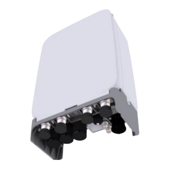
Unit: in. (mm) [Top View] 11.4 (289.4) [Left View] [Right View] [Rear View] [Front View] [Bottom View] System External Interface The figure below depicts the external interface structure of the RRH system. RT4401-48A Installation Manual v3.0 Copyright © 2019, All Rights Reserved. -
Page 19: Figure 3. System External Interface (Rrh Only)
Figure 3. System External Interface (RRH only) ANT 1 ANT 2 ANT 3 ANT 4 DC_PWR Ground Terminal Figure 4. System External Interface (with Clip-on: Antenna + AC-DC Power Unit) AC_PWR Ground Terminal DC_PWR RT4401-48A Installation Manual v3.0 Copyright © 2019, All Rights Reserved. - Page 20 Chapter 1 Before Installation When interoperating the AC-DC power unit, the ground cable must be connected to the ground terminal of the AC-DC power unit. RT4401-48A Installation Manual v3.0 Copyright © 2019, All Rights Reserved.
-
Page 21: Specifications
Vibration in Use Office Vibration Transportation Vibration Transportation Vibration Noise Fanless (natural convection cooling) Wind Resistance Telcordia GR-487-CORE, Section 3.34 FCC Title 47, CFR Part 96 Safety UL 60950-1 2nd ED RT4401-48A Installation Manual v3.0 Copyright © 2019, All Rights Reserved. -
Page 22: Table 2. Ac/Dc Power Unit Specifications
Chapter 1 Before Installation Item RT4401-48A UL 62368-1 UL 60950-22 FCC Title 47, CFR Part 96 The table below outlines the AC/DC power unit specifications of the RRH system. RT4401-48A Installation Manual v3.0 Copyright © 2019, All Rights Reserved. -
Page 23: Cautions For Installation
When operator installs the RRH, the RRH must be within the protective angle (left/right side 45° each from the central axis) to prevent the RRH from lightning RT4401-48A Installation Manual v3.0 Copyright © 2019, All Rights Reserved. -
Page 24: After Installing
Ensure that the workers do not damage installed cables while cleaning the system. While cleaning the power supply device, take precaution that the device does not come in contact with foreign objects that may cause power failure. RT4401-48A Installation Manual v3.0 Copyright © 2019, All Rights Reserved. -
Page 25: Installation Tools
17 mm Tightening M10 hexagonal. bolt 19 mm Tightening M12 hexagonal. bolt Mini DIN Male Torque TQ-78-F8 Tightening 4.3-10 and mini din Wrench connector Tape Measure 16 ft./150 ft. Measuring length RT4401-48A Installation Manual v3.0 Copyright © 2019, All Rights Reserved. - Page 26 Apply cable thickness: 1.5 to 6.2 Removing cable sheath in. (4 to 16 mm) Nipper Basic Tool Cutting cable Flush cutter Basic Tool For cutting cable tie Industrial Scissor Basic Tool Cutting RT4401-48A Installation Manual v3.0 Copyright © 2019, All Rights Reserved.
- Page 27 The required installation tools may vary depending on the site conditions. In addition to the basic tools, protractor, ladder, safety equipment, and cleaning tools must also be arranged, considering the site conditions. RT4401-48A Installation Manual v3.0 Copyright © 2019, All Rights Reserved.
-
Page 28: Chapter 2 Installing System
Installing the system with the power switch ON may cause system damage or fatal human injury when connecting or disconnecting the cables. To prevent the risk of electrical shock, do not wear accessories such as watches and rings. RT4401-48A Installation Manual v3.0 Copyright © 2019, All Rights Reserved. -
Page 29: System Arrangement
Figure 6. RRH Arrangement_1 Sector Pole Type Installation Unit: in. (mm) ※ Example for 100 A pole Pole (Ф 4.5 in./114.3 mm) ≥ 8 (200) ≥ 8 (200) [Top View] [Front View] RT4401-48A Installation Manual v3.0 Copyright © 2019, All Rights Reserved. -
Page 30: Figure 7. Rrh Arrangement_1 Sector Wall Type Installation
Figure 8. RRH Arrangement_1 Sector Tilting Unit: in. (mm) [Down Tilting 15°] [Up Tilting 15°] 11.6 (294) 13.7 (348) [Pole Type] [Pole Type] 12 (304) 14.1 (358) [Wall Type] [Wall Type] RT4401-48A Installation Manual v3.0 Copyright © 2019, All Rights Reserved. -
Page 31: Figure 9. Rrh Arrangement_Swivelling
[Wall Type] The dimensions of the front of the RRH change according to the tilt angle, and the maximum dimensions are described in the figure above. (RRH Arrangement_Left, Right Swivelling 30°). RT4401-48A Installation Manual v3.0 Copyright © 2019, All Rights Reserved. -
Page 32: Using Tilting Bracket
Figure 11. RRH Arrangement_3 Sector Tilting Unit: in. (mm) [Down Tilting 15°] [Up Tilting 15°] 27.7 (704) 30.9 (786) ※ Example for 200 A pole ※ Example for 200 A pole [Top View] [Top View] RT4401-48A Installation Manual v3.0 Copyright © 2019, All Rights Reserved. -
Page 33: Without Tilting Bracket
[Top View] Using Side by Side Bracket The figures below depict the recommended distances for each direction of the RRH using the side by side bracket for the pole type installation. RT4401-48A Installation Manual v3.0 Copyright © 2019, All Rights Reserved. -
Page 34: Figure 13. Rrh Arrangement_3 Sector Pole Type Side By Side Installation
8.7 in. (220 mm) Figure 14. RRH Arrangement_3 Sector Wall Type Side by Side Installation 15.75 (400) Unit: in. (mm) ≥ 32 (800) ≥ 32 (800) [Front View] [Top View] RT4401-48A Installation Manual v3.0 Copyright © 2019, All Rights Reserved. -
Page 35: Transporting And Unpacking
Unpack the inner packaging after each system is placed on its installation location. Dispose by-products (packaging waste) in accordance with waste management rules. Do not recycle the by-products. RT4401-48A Installation Manual v3.0 Copyright © 2019, All Rights Reserved. -
Page 36: Fixing Rrh
Check the position for mounting the clip on antenna on the front of the RRH and place it in that position. Figure 15. Assembling Clip on Antenna (1) Clip on Antenna RT4401-48A Installation Manual v3.0 Copyright © 2019, All Rights Reserved. -
Page 37: Figure 16. Assembling Clip On Antenna (2)
When inserting the port seal to RRH ANT port, take care of the direction. - The screw thread of port seal should be downwards. Port Seal Screw thread Screw thread RT4401-48A Installation Manual v3.0 Copyright © 2019, All Rights Reserved. -
Page 38: Figure 17. Assembling Clip On Antenna (3)
Chapter 2 Installing System Figure 17. Assembling Clip on Antenna (3) ANT Port Port Seal Connect the RF connector of clip on antenna to the RRH ANT 1, 2, 3, 4 port. RT4401-48A Installation Manual v3.0 Copyright © 2019, All Rights Reserved. -
Page 39: Figure 18. Assembling Clip On Antenna (4)
When connecting the RF cable, check the color of the tags on the side of RF cable. ANT1 ANT2 ANT4 ANT3 RF Port Tag Color ANT1 ANT2 Orange ANT3 Yellow ANT4 Aqua blue Push weatherproof boots up to the port seal. RT4401-48A Installation Manual v3.0 Copyright © 2019, All Rights Reserved. -
Page 40: Assembling Ac-Dc Power Unit
M5 Torx Screw 25 lbfin Torque Driver (20 to 90 lbf·in) Working Tools Screw Driver Bit (T25H) Place an AC-DC power unit to the right side of the RRH. RT4401-48A Installation Manual v3.0 Copyright © 2019, All Rights Reserved. -
Page 41: Figure 20. Assembling Ac-Dc Power Unit (1)
Chapter 2 Installing System Figure 20. Assembling AC-DC Power Unit (1) Hook AC-DC Power Unit Fix the AC-DC power unit using the fasteners. RT4401-48A Installation Manual v3.0 Copyright © 2019, All Rights Reserved. -
Page 42: Using Tilting And Swiveling Bracket
M6 hexagonal bolt 43 lbfin Torque Wrench (10 to 50 lbfin) Working Tools Torque Wrench Spanner Head (apply hexagonal head: 10 mm) Spanner (apply hexagonal head: 13 mm) RT4401-48A Installation Manual v3.0 Copyright © 2019, All Rights Reserved. -
Page 43: Figure 22. Fixing Unit Bracket (1)
Check the position for mounting the unit bracket on the back of the RRH and place it in that position. Figure 23. Fixing Unit Bracket (2) Unit Bracket Unit Bracket Fixing Point Fix the unit bracket using the fasteners. RT4401-48A Installation Manual v3.0 Copyright © 2019, All Rights Reserved. -
Page 44: Figure 24. Fixing Unit Bracket (3)
Torque Driver (20 to 90 lbfin) Working Tools Screw Driver Bit ('+', No. 3) Antenna Alignment Tool Pass the steel band through the fixing hole of the mounting bracket. RT4401-48A Installation Manual v3.0 Copyright © 2019, All Rights Reserved. -
Page 45: Figure 25. Fixing Mounting Bracket On The Pole (1)
Mounting Bracket Place the mounting bracket to the pole. Figure 26. Fixing Mounting Bracket on the Pole (2) Pole Fix the mounting bracket to the pole using the steel band. RT4401-48A Installation Manual v3.0 Copyright © 2019, All Rights Reserved. -
Page 46: Figure 27. Fixing Mounting Bracket On The Pole (3)
When fixing the mounting bracket on the pole, ensure to check the level of bracket. After finishing the installation, adjust the level minutely. RT4401-48A Installation Manual v3.0 Copyright © 2019, All Rights Reserved. -
Page 47: Figure 29. Lifting Rrh
Torque Wrench (100 to 400 lbfin) Working Tools Torque Wrench Spanner Head (apply hexagon head: 13 mm) RF Alignment Tool Place the unit bracket on the fixing groove of the mounting bracket. RT4401-48A Installation Manual v3.0 Copyright © 2019, All Rights Reserved. -
Page 48: Figure 30. Fixing Rrh On The Pole (1)
Chapter 2 Installing System Figure 30. Fixing RRH on the Pole (1) Unit Bracket M6 Hex. Bolt Fixing Groove Fix the RRH using the fasteners. RT4401-48A Installation Manual v3.0 Copyright © 2019, All Rights Reserved. -
Page 49: Figure 31. Fixing Rrh On The Pole (2)
Check the tilt and the azimuth using the RF alignment tool, and adjust when there is an issue. For detailed instructions of how to use the RF alignment tool, refer to the user manual per manufacturer. RT4401-48A Installation Manual v3.0 Copyright © 2019, All Rights Reserved. -
Page 50: Table 9. Tools For Marking
This will reduce marking error range. Check the distance between the location for fixing the RRH and the anchor bolt hole. RT4401-48A Installation Manual v3.0 Copyright © 2019, All Rights Reserved. -
Page 51: Figure 32. Rrh Marking Dimensions
Place a mounting bracket on the fixing location, and then check the level status using a level, and adjust the level of bracket assembly. If the level status is normal, mark the anchor bolt holes on a wall. RT4401-48A Installation Manual v3.0 Copyright © 2019, All Rights Reserved. -
Page 52: Figure 33. Marking
(17 mm) 1.7 in. (44 mm) * Remove the debris from the drilled hole. Drill the anchor holes at the marked points. Remove dust from the holes using a vacuum cleaner. RT4401-48A Installation Manual v3.0 Copyright © 2019, All Rights Reserved. -
Page 53: Figure 34. Drilling
Torque Wrench Spanner head (apply Hex. head: 17 mm) Spanner (17 mm) Hammer Anchor Punch (for M10 set anchor bolt) Fix the anchor to the drilled hole. RT4401-48A Installation Manual v3.0 Copyright © 2019, All Rights Reserved. -
Page 54: Figure 35. Fixing Mounting Bracket On The Wall (1)
To fix the RRH on the wall, do the following: Prerequisites Before proceeding with fixing the RRH on the wall, make sure that you have the items mentioned in the table below: RT4401-48A Installation Manual v3.0 Copyright © 2019, All Rights Reserved. -
Page 55: Figure 37. Fixing Rrh On The Wall (1)
Place the unit brack7et on the fixing groove of the mounting bracket. Figure 37. Fixing RRH on the Wall (1) Unit Bracket Fixing Groove Mounting Bracket Fix the RRH using the fasteners. RT4401-48A Installation Manual v3.0 Copyright © 2019, All Rights Reserved. -
Page 56: Figure 38. Fixing Rrh On The Wall (2)
- Up tilting: 0° to 16° To adjust the RRH tilting, do the following: Prerequisites Before proceeding with adjusting the RRH tilting, make sure that you have the items mentioned in the table below: RT4401-48A Installation Manual v3.0 Copyright © 2019, All Rights Reserved. -
Page 57: Figure 39. Rrh Tilting Adjustment (1)
(Washer Assembly) M8 Hex. Bolt (Washer Assembly) ※ Do not separate it completely. Push the RRH down to adjust the tilting angle and fix the RRH using the working tools. RT4401-48A Installation Manual v3.0 Copyright © 2019, All Rights Reserved. -
Page 58: Figure 40. Rrh Tilting Adjustment (2)
Chapter 2 Installing System Figure 40. RRH Tilting Adjustment (2) Down tilting 16° Example M8 Hex. Bolt (Washer Assembly) When executing up tilting, use the same method with down tilting. RT4401-48A Installation Manual v3.0 Copyright © 2019, All Rights Reserved. -
Page 59: Figure 41. Rrh Tilting Adjustment (3)
The instructions for swiveling the RRH apply to all installation types. The adjustable swivelling is as follows: - Left Swivelling: 0° to 30° - Right Swivelling: 0° to 30° To adjust the RRH swivelling, do the following RT4401-48A Installation Manual v3.0 Copyright © 2019, All Rights Reserved. -
Page 60: Figure 42. Rrh Swivelling Adjustment (1)
Loosen the RRH by turning M12 hexagonal nut of mounting bracket two or three times counter clockwise. Do not separate it completely. Figure 42. RRH Swivelling Adjustment (1) M12 Hex. Nut Pull the RRH left/right to adjust the swivelling angle. RT4401-48A Installation Manual v3.0 Copyright © 2019, All Rights Reserved. -
Page 61: Figure 43. Rrh Swivelling Adjustment (2)
Chapter 2 Installing System Figure 43. RRH Swivelling Adjustment (2) [Left Swivelling Adjustment] [Left Swivelling 30° Example] [Right Swivelling Adjustment] [Right Swivelling 30° Example] Fix the RRH using the working tools. RT4401-48A Installation Manual v3.0 Copyright © 2019, All Rights Reserved. -
Page 62: Using Tilting Bracket
This section describes the procedure to fix the unit bracket using the tilting bracket. Fixing Unit Bracket These instructions for mounting a unit bracket to the RRH apply to all installation types. RT4401-48A Installation Manual v3.0 Copyright © 2019, All Rights Reserved. -
Page 63: Table 16. Parts And Tools For Fixing Unit Bracket On Rrh
Three RRHs can be installed when the pole diameter is more than 8 in. (200 A, 220 mm) to 12 in. (300 A, 320 mm). The length of the steel band is 930 mm, 1160 mm, and 1330 mm, and it is used RT4401-48A Installation Manual v3.0 Copyright © 2019, All Rights Reserved. -
Page 64: Figure 45. Fixing Mounting Bracket On The Pole (1)
Pass the steel band through the fixing hole of the mounting brackets. Figure 45. Fixing Mounting Bracket on the Pole (1) Steel Band Mounting Bracket-0 Mounting Bracket-0 Mounting Bracket-1 Mounting Bracket-2 Mounting Bracket-0 RT4401-48A Installation Manual v3.0 Copyright © 2019, All Rights Reserved. -
Page 65: Figure 46. Fixing Mounting Bracket On The Pole (2)
Fix the mounting brackets to the pole using the steel band. Figure 47. Fixing Mounting Bracket on the Pole (3) Check the level of each mounting brackets on the pole and adjust the level. RT4401-48A Installation Manual v3.0 Copyright © 2019, All Rights Reserved. -
Page 66: Figure 48. Fixing Mounting Bracket On The Pole (4)
After fixing the steel band, push the remainder of band inside the mounting bracket Lifting RRH To lift the RRH, do the following: Lift the RRH with a cherry picker. RT4401-48A Installation Manual v3.0 Copyright © 2019, All Rights Reserved. -
Page 67: Figure 49. Lifting Rrh
Working Tools Torque Wrench Spanner Head (apply Hex. head: 13 mm) Antenna Alignment Tool Place the unit bracket of RRH-0 on the fixing groove of the mounting bracket. RT4401-48A Installation Manual v3.0 Copyright © 2019, All Rights Reserved. -
Page 68: Figure 50. Fixing Rrhs On The 3Sector Pole Type (1)
Chapter 2 Installing System Figure 50. Fixing RRHs on the 3Sector Pole Type (1) Unit Bracket RRH-0 Fixing Groove Mounting Bracket Fix the RRH-0 using the fasteners. RT4401-48A Installation Manual v3.0 Copyright © 2019, All Rights Reserved. -
Page 69: Figure 51. Fixing Rrhs On The 3Sector Pole Type (2)
Tilting angle scale of the unit bracket [Angle pointer position for unit bracket with 0° tilt when installing the RRH] Fix the RRH-1 and RRH-2 in the same way as the RRH-0. RT4401-48A Installation Manual v3.0 Copyright © 2019, All Rights Reserved. -
Page 70: Without The Tilting Bracket
Torque Wrench Spanner Head (apply Hex. head: 10 mm) Check the position for mounting the unit bracket on the back of the RRH and place it in that position. RT4401-48A Installation Manual v3.0 Copyright © 2019, All Rights Reserved. -
Page 71: Figure 53. Fixing Unit Bracket (1)
Three RRHs can be installed when the pole diameter is than 8 in. (200 A, 220 mm) to 12 in. (300 A, 320 mm). The length of the steel band is 930 mm, 1160 mm, and 1330 mm, and it is used RT4401-48A Installation Manual v3.0 Copyright © 2019, All Rights Reserved. -
Page 72: Table 20. Parts And Tools For Fixing Mounting Bracket On The Pole
Torque Driver (20 to 90 lbfin) Working Tools Screw Driver Bit ('+', No. 3) Antenna Alignment Tool Pass the steel band through the fixing hole of the mounting brackets. RT4401-48A Installation Manual v3.0 Copyright © 2019, All Rights Reserved. -
Page 73: Figure 55. Fixing Mounting Bracket On The Pole (1)
Chapter 2 Installing System Figure 55. Fixing Mounting Bracket on the Pole (1) Steel Band Mounting Bracket-0 Mounting Bracket-0 Mounting Bracket-1 Mounting Bracket-0 Mounting Bracket-2 Place the mounting brackets to the pole. RT4401-48A Installation Manual v3.0 Copyright © 2019, All Rights Reserved. -
Page 74: Figure 56. Fixing Mounting Bracket On The Pole (2)
Fix the mounting brackets to the pole using the steel band. Figure 57. Fixing Mounting Bracket on the Pole (3) Check the level of each mounting brackets on the pole and adjust the level. RT4401-48A Installation Manual v3.0 Copyright © 2019, All Rights Reserved. -
Page 75: Figure 58. Fixing Mounting Bracket On The Pole (4)
Torque Driver (20 to 90 lbf·in) Antenna Alignment Tool Pull out the fastening materials so that they do not extend out from the fixing groove of the unit bracket. Do not pull out completely. RT4401-48A Installation Manual v3.0 Copyright © 2019, All Rights Reserved. -
Page 76: Figure 59. Fixing Rrhs On The Pole (1)
Unit Bracket RRH-1 RRH-2 [Top View] Place the unit bracket on the fixing grooves of the mounting bracket and push the unit bracket down to fix the RRH-0 in place. RT4401-48A Installation Manual v3.0 Copyright © 2019, All Rights Reserved. -
Page 77: Figure 60. Fixing Rrhs On The Pole (2)
Mounting Bracket Fix the unit bracket of the RRH-0 to the mounting bracket using the fastener. Figure 61. Fixing RRHs on the Pole (3) M6 Torx Screw Unit Bracket RRH-0 RT4401-48A Installation Manual v3.0 Copyright © 2019, All Rights Reserved. -
Page 78: Using Side By Side Bracket
M6 hexagonal bolt 43 lbfin Torque Wrench (10 to 50 lbfin) Working Tools Torque Wrench Spanner Head (apply hexagonal head: 10 mm) Spanner (apply hexagonal head: 13 mm) RT4401-48A Installation Manual v3.0 Copyright © 2019, All Rights Reserved. -
Page 79: Figure 63. Fixing Unit Bracket_Side Installation (1)
The standard of the pole on which the mounting bracket can be attached using steel bands is 50 A to 100 A. Assembling Mounting Bracket To assemble the mounting bracket for 1 sector, do the following: RT4401-48A Installation Manual v3.0 Copyright © 2019, All Rights Reserved. -
Page 80: Figure 65. Assembling Mounting Bracket Assembly_Pole Type (1)
Side by Side Bracket M10 Stud Bolt Assembly Insert the rear mounting bracket with aligning the hole and stud bolt at the left lower side of side by side bracket. RT4401-48A Installation Manual v3.0 Copyright © 2019, All Rights Reserved. -
Page 81: Figure 66. Assembling Mounting Bracket Assembly_Pole Type (2)
Table 24. Parts and Tools for Fixing Side by Side Bracket Assembly_Pole Type Category Description Parts Side by Side Bracket Assembly 1 EA RT4401-48A Installation Manual v3.0 Copyright © 2019, All Rights Reserved. -
Page 82: Figure 68. Fixing Side By Side Bracket Assembly_Pole Type (1)
Figure 69. Fixing Side by Side Bracket Assembly_Pole Type (2) Rear Mounting Bracket Place the rest three stud bolts to the rear mounting bracket holes and fix the stud bolts using the fasteners. RT4401-48A Installation Manual v3.0 Copyright © 2019, All Rights Reserved.