Advertisement
Quick Links
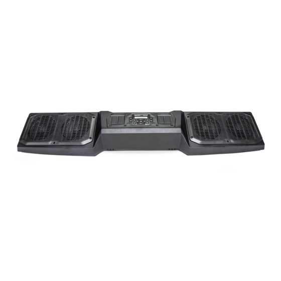
VISOR AUDIO KIT
P/N 2882888, 2882891
APPLICATION
Verify accessory fitment at Polaris.com.
BEFORE YOU BEGIN
Read these instructions and check to be sure all parts and tools are accounted for. Please retain these
installation instructions for future reference and parts ordering information.
KIT CONTENTS
This kit only contains visor audio and associated components. Installation of the following additional kits is also
required (sold separately):
• One of the following Roof Kits: PN 2882911, 2882912, 2882913, 2883274, 2883277, or equivalent
• Roof Power Kit, PN 2882904
• If installing Visor Audio Kit PN 2882891 in a vehicle with RIDE COMMAND
®
pre-installed from the factory,
then RIDE COMMAND
®
Audio Adapter Kit PN 2883232 is also required.
This Kit includes:
NOTE
Kit PN 2882888 shown; Kit PN 2882891 similar except as noted below.
Instr 9928087
Rev 03 2018-12
Page 1 of 17
Advertisement

Summary of Contents for Polaris 2882888
- Page 1 RIDE COMMAND ® Audio Adapter Kit PN 2883232 is also required. This Kit includes: NOTE Kit PN 2882888 shown; Kit PN 2882891 similar except as noted below. Instr 9928087 Rev 03 2018-12 Page 1 of 17...
- Page 2 - Speaker (not shown) 4017467 Conduit, A-pillar 5414966 Input, Auxiliary (Kit 2882888 only) 2636834 Nut, Hex Flange - M5 X 0.8 (Kit 2882888 only) 7547437 Harness, Antenna Signal (with boot) (Kit 2882888 only) 2411489 Ground Strap, Antenna, AM/FM (Kit 2882888 only) 4017858...
-
Page 3: Tools Required
PART DESCRIPTION PART NUMBER Screw, Torx ® Truss Head - M6 X 1.0 X 40 7519001 Washer, Steel - 0.281 X 1.00 X 0.051 7556329 Washer, Rubber - 7.1 X 25.4 X 1.6 7556879 Spacer - 0.34 ID X 0.56 OD X 0.31 7556373 Bracket, Internal ROPS, LH 5266293... - Page 4 HARNESS DETAIL AUDIO UNIT (Kit PN 2882888 only): PART DESCRIPTION WIRE PIN QTY/ CONNECTS TO COLOR GENDER Connector, Rear/Door Speaker, LH (with Green* 2 female OPTIONAL: See installation cap) section, AUDIO UNIT AND HARNESSES, Step 2. Connector, Rear/Door Speaker, RH (with...
- Page 5 AUDIO UNIT (Kit PN 2882891 only): PART DESCRIPTION WIRE PIN QTY/ CONNECTS TO COLOR GENDER Connector, Rear/Door Speaker, LH (with Green* 2 female OPTIONAL: See installation cap) section, AUDIO UNIT AND HARNESSES, Step 2. Connector, Rear/Door Speaker, RH (with Purple* 2 female Note: Splitter harnesses not cap)
-
Page 6: Installation Instructions
AUXILIARY INPUT PART DESCRIPTION WIRE PIN QTY/ CONNECTS TO COLOR GENDER Connector, USB Head unit , connector 1F Connector, 3.5 mm Stereo 4 male Head unit , connector 1E ANTENNA HARNESS PART DESCRIPTION WIRE PIN QTY/ CONNECTS TO COLOR GENDER Connector, Antenna Signal Head unit , connector 1G... - Page 7 4. Remove upper dash cupholder (or existing dash b. Remove seven push darts from rear liner: audio unit PN 2882750, sold separately) by five from front edge and two from rear edge. removing two push pin rivets , then slide Retain any two of seven push darts;...
- Page 8 e. Remove front roof liner by removing two each c. Remove four screws from rear edge of roof screws and washers . Front liner and panel. Retain screws. hardware will not be reused. When reinstalling roof at end of procedure, torque screws to specification.
- Page 9 e. Slide roof panel forward until three front hooks c. Detach front roof panel from rear roof panel by removing eight screws . Retain screws. unlock from ROPS visor, then lift roof from ROPS and set aside. When reinstalling roof at end of procedure, torque screws to specification.
- Page 10 INSTALL ROOF SUPPORT BRACKETS NOTE Non-crew shown; crew similar. 1. Remove two clip nuts from standoffs at front of roof panel (if installed). Clip nuts will not be reused. 4. Identify LH internal ROPS bracket and RH internal ROPS bracket 2.
- Page 11 Visor shown partially transparent and other harnesses hidden for clarity. 3. OPTIONAL (Kit PN 2882888 only): If additional audio components are being installed (e.g., Subwoofer Kit), then join audio signal connector 1H and audio remote bullet connector 1J to corresponding audio component connectors.
- Page 12 • Antenna signal harness (to connector 1G) (Kit 2882888 only) • Auxiliary input harness (to connectors 1E and 1F) (Kit 2882888 only) • Audio signal and remote harness (to connectors 1K and 1L) (Kit 2882891 only) • Any other harnesses connected in previous OPTIONAL steps c.
- Page 13 INSTALL ANTENNA (KIT PN 2882888 ONLY) 8. Route auxiliary input connectors 1E and 1F (Kit 2882888) or audio signal and remote connectors NOTE 1K and 1L (Kit 2882891) outboard to top of driver side A-pillar, down through conduit , down...
- Page 14 2. Insert threaded post and alignment pin located on antenna base through drilled holes in fender, attach one end of ground strap and connector 5B on antenna signal harness , then secure with . Install rubber boot. IMPORTANT Do NOT remove existing nut (pre-installed) from threaded post.
- Page 15 Remove nut and rubber gasket from auxiliary input, route wires rearward through opening, then reinstall gasket and nut. INSTALL AUXILIARY INPUT (KIT 2882888 ONLY) 1. Gain access. 3. Reconnect electrical harnesses disconnected in a.
-
Page 16: Decal Application
When reinstalling roof liner in Step 6b, five push darts removed from front edge of (front) liner will not be reinstalled. Liner tucks between visor audio and 3. Kit PN 2882888 only: Carefully examine routing of roof panel. antenna signal harness... -
Page 17: Feedback Form
FEEDBACK FORM A feedback form has been created for the installer to provide any comments, questions or concerns about the installation instructions. The form is viewable on mobile devices by scanning the QR code or by clicking HERE if viewing on a PC. Instr 9928087 Rev 03 2018-12 Page 17 of 17...